US185241A - Improvement in fenders for printing-presses - Google Patents
Improvement in fenders for printing-presses Download PDFInfo
- Publication number
- US185241A US185241A US185241DA US185241A US 185241 A US185241 A US 185241A US 185241D A US185241D A US 185241DA US 185241 A US185241 A US 185241A
- Authority
- US
- United States
- Prior art keywords
- platen
- fender
- fenders
- presses
- printing
- Prior art date
- Legal status (The legal status is an assumption and is not a legal conclusion. Google has not performed a legal analysis and makes no representation as to the accuracy of the status listed.)
- Expired - Lifetime
Links
Images
Classifications
-
- D—TEXTILES; PAPER
- D06—TREATMENT OF TEXTILES OR THE LIKE; LAUNDERING; FLEXIBLE MATERIALS NOT OTHERWISE PROVIDED FOR
- D06F—LAUNDERING, DRYING, IRONING, PRESSING OR FOLDING TEXTILE ARTICLES
- D06F71/00—Apparatus for hot-pressing clothes, linen or other textile articles, i.e. wherein there is substantially no relative movement between pressing element and article while pressure is being applied to the article; Similar machines for cold-pressing clothes, linen or other textile articles
- D06F71/32—Details
- D06F71/323—Protective devices, e.g. burn guards
-
- Y—GENERAL TAGGING OF NEW TECHNOLOGICAL DEVELOPMENTS; GENERAL TAGGING OF CROSS-SECTIONAL TECHNOLOGIES SPANNING OVER SEVERAL SECTIONS OF THE IPC; TECHNICAL SUBJECTS COVERED BY FORMER USPC CROSS-REFERENCE ART COLLECTIONS [XRACs] AND DIGESTS
- Y10—TECHNICAL SUBJECTS COVERED BY FORMER USPC
- Y10T—TECHNICAL SUBJECTS COVERED BY FORMER US CLASSIFICATION
- Y10T74/00—Machine element or mechanism
- Y10T74/21—Elements
- Y10T74/2193—Guard mechanisms
- Y10T74/2194—Automatic
- Y10T74/2195—Oscillating member actuator
Definitions
- the platen-fender for preventing the fingers of an attendant from being caught and pinched between the platen and bed, is shown at A as composed, in part, of two levers, a a, and two connection-bars, b 11, arranged as represented.
- These levers disposed on opposite edges of the platen B, have a pivotal shaft, 0, which, fixed in them, goes through and turns in bearings in the platen-supporting frame G, and has fixed to its middle the sheet-holder or clamp D, which, as shown, is a thin blade or arm, that extends underneath and rests against the cross-bar b of the fender. It moves with and is moved by the fender.
- an arm,f carrying a friction-roller, 9, projects in manner as shown.
- This friction-roller rests at its periphery upon that of a cam, 71, fixed to the inner side of the fly-wheel i.
- a rod, k is pivoted. It slides through a support-bar, Z, and goes through a helical spring, m, which bears at its ends against the bars I) and Z.
- This spring serves to depress or move the fender A in one direction, it being moved the opposite way by the cam acting against the friction-roller, which it will do during part of the revolution of the said cam.
- the fender A and the sheet-holder D are to be brought down even with the platen a short time before the bed F may go down to its lowest position. Should the hand of an attendant be resting upon the platen or sheet of paper during a descent of the fender, thelatter, by gently falling upon the arm or wrist, will warn the attendant to remove his hand from the platen in time to prevent the fingers from being caught between and crushed by the platen and bed.
- My present fender does nothing of the kind, but simply descends gently upon the wrist or arm without force sufficient to injure it, and thereby warns the attendant of his danger in time to prevent his fingers or wrist from being injured by the bed.
- the sheetholder In combination with the lever-fender, provided with the operative spring and cam, and arranged with and applied to the platen or its supporting-frame, as described, the sheetholder, arranged at right angles with and fixed to the fender pivotal shaft, and extended under and against the front cross-bar of the fender, all being substantially as set forth.
Landscapes
- Engineering & Computer Science (AREA)
- Textile Engineering (AREA)
- Handling Of Sheets (AREA)
Description
W. P. KIDDER.
FENDERS FOR PRINTING PRESSES. 116,185,241. Patented Dec. 12, 1876.
licgzizzzlfulilddar THE GRAPHIC CILNVY UNITED sTnTns PATENT @TTron.
WELLINGTON P. KIDDER, OF MALDEN, MASSACHUSETTS.
IMPROVEMENTIN FENDERS FOR PRlNTlNG-PRESSES.
Specification forming part of Letters Patent No. 185,241, dated December 12, 1876; application filed August 25, 1876.
To all whom it may concern:
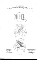
Be it known that I, WELLINGTON P. KID- DER, of Malden, of the county of Middlesex and State of Massachusetts, have invented a new and useful Improvement in Fenders for Printing-Presses; and do hereby declare the same to be fully described in the following specification, and represented in the aecompanying drawings, of which Figure 1 denotes a top view; Fig. 2, a side elevation, and Fig. 3 a longitudinal section, of my invention with the parts of a printingpress to which it is applied.
In this press the platen-fender, for preventing the fingers of an attendant from being caught and pinched between the platen and bed, is shown at A as composed, in part, of two levers, a a, and two connection-bars, b 11, arranged as represented. These levers, disposed on opposite edges of the platen B, have a pivotal shaft, 0, which, fixed in them, goes through and turns in bearings in the platen-supporting frame G, and has fixed to its middle the sheet-holder or clamp D, which, as shown, is a thin blade or arm, that extends underneath and rests against the cross-bar b of the fender. It moves with and is moved by the fender. From the lever a an arm,f, carrying a friction-roller, 9, projects in manner as shown. This friction-roller rests at its periphery upon that of a cam, 71, fixed to the inner side of the fly-wheel i. To the middle of the cross-bar I) a rod, k, is pivoted. It slides through a support-bar, Z, and goes through a helical spring, m, which bears at its ends against the bars I) and Z. This spring serves to depress or move the fender A in one direction, it being moved the opposite way by the cam acting against the friction-roller, which it will do during part of the revolution of the said cam. The fender A and the sheet-holder D are to be brought down even with the platen a short time before the bed F may go down to its lowest position. Should the hand of an attendant be resting upon the platen or sheet of paper during a descent of the fender, thelatter, by gently falling upon the arm or wrist, will warn the attendant to remove his hand from the platen in time to prevent the fingers from being caught between and crushed by the platen and bed.
In patents heretofore granted to me the fender has been represented as so applied to the platen as to move along such in a manner to suddenly press against and force the wrist off the platen, in order to prevent accident or crushing the fingers.
My present fender does nothing of the kind, but simply descends gently upon the wrist or arm without force sufficient to injure it, and thereby warns the attendant of his danger in time to prevent his fingers or wrist from being injured by the bed.
I therefore do not herein claim a fender supported by slides applied to the edges of the platen, and to move up and down thereon; nor do I claim a spring or sheet-holder pivoted or attached to the platen, and extended up underneath and against the fender, all be ing as shown in patents heretofore granted to me.
I claim- In combination with the lever-fender, provided with the operative spring and cam, and arranged with and applied to the platen or its supporting-frame, as described, the sheetholder, arranged at right angles with and fixed to the fender pivotal shaft, and extended under and against the front cross-bar of the fender, all being substantially as set forth.
VVELLINGION P. KIDDER.
Witnesses:
R. H. EDDY, S. N. PIPER.
Publications (1)
| Publication Number | Publication Date |
|---|---|
| US185241A true US185241A (en) | 1876-12-12 |
Family
ID=2254646
Family Applications (1)
| Application Number | Title | Priority Date | Filing Date |
|---|---|---|---|
| US185241D Expired - Lifetime US185241A (en) | Improvement in fenders for printing-presses |
Country Status (1)
| Country | Link |
|---|---|
| US (1) | US185241A (en) |
-
0
- US US185241D patent/US185241A/en not_active Expired - Lifetime
Similar Documents
| Publication | Publication Date | Title |
|---|---|---|
| US185241A (en) | Improvement in fenders for printing-presses | |
| US160333A (en) | Improvement in printing-presses | |
| US1066459A (en) | Safety appliance for hand-fed power-presses. | |
| US484751A (en) | Alonzo bell | |
| US1231577A (en) | Safety device for addressing-machines. | |
| US80444A (en) | William braidwood | |
| US1024848A (en) | Hardy-operating device. | |
| US131950A (en) | Improvement in printing-presses | |
| US733412A (en) | Safety device for punch-presses. | |
| US1157247A (en) | Safety-guard for printing-presses. | |
| US411258A (en) | Printing-press hand-protector | |
| US516317A (en) | Perforating attachment for printing-presses | |
| US1394501A (en) | Press-guard | |
| US143374A (en) | Improvement in register-point-perforating devices | |
| US727436A (en) | Platen-press. | |
| US83471A (en) | Improvement in printing-presses | |
| US294473A (en) | Paper-folding machine | |
| US1298567A (en) | Safety device. | |
| US58563A (en) | Improvement in stop-cutters for cutting continuous sheets of paper into shorter ones | |
| US1129301A (en) | Safety device for power stamping-presses. | |
| US1135399A (en) | Guard for platen printing-presses. | |
| US478079A (en) | Paper-straightener for printing-presses | |
| US1226260A (en) | Combined safety and throw-off mechanism. | |
| US1236146A (en) | Safety device for machinery. | |
| US230740A (en) | Cylinder printing-machine |