US1852406A - Relay - Google Patents
Relay Download PDFInfo
- Publication number
- US1852406A US1852406A US428090A US42809030A US1852406A US 1852406 A US1852406 A US 1852406A US 428090 A US428090 A US 428090A US 42809030 A US42809030 A US 42809030A US 1852406 A US1852406 A US 1852406A
- Authority
- US
- United States
- Prior art keywords
- relay
- signal
- relays
- track
- energized
- Prior art date
- Legal status (The legal status is an assumption and is not a legal conclusion. Google has not performed a legal analysis and makes no representation as to the accuracy of the status listed.)
- Expired - Lifetime
Links
- 230000005291 magnetic effect Effects 0.000 description 21
- 238000004804 winding Methods 0.000 description 19
- 230000004907 flux Effects 0.000 description 15
- 230000007935 neutral effect Effects 0.000 description 12
- 230000005540 biological transmission Effects 0.000 description 2
- 230000008859 change Effects 0.000 description 2
- 230000005389 magnetism Effects 0.000 description 2
- 230000007246 mechanism Effects 0.000 description 2
- 238000004353 relayed correlation spectroscopy Methods 0.000 description 2
- 241000501754 Astronotus ocellatus Species 0.000 description 1
- UIIMBOGNXHQVGW-UHFFFAOYSA-M Sodium bicarbonate Chemical compound [Na+].OC([O-])=O UIIMBOGNXHQVGW-UHFFFAOYSA-M 0.000 description 1
- 230000006978 adaptation Effects 0.000 description 1
- 230000004075 alteration Effects 0.000 description 1
- 238000013459 approach Methods 0.000 description 1
- JXSJBGJIGXNWCI-UHFFFAOYSA-N diethyl 2-[(dimethoxyphosphorothioyl)thio]succinate Chemical compound CCOC(=O)CC(SP(=S)(OC)OC)C(=O)OCC JXSJBGJIGXNWCI-UHFFFAOYSA-N 0.000 description 1
- 238000012986 modification Methods 0.000 description 1
- 230000004048 modification Effects 0.000 description 1
- 230000003287 optical effect Effects 0.000 description 1
- 229940061319 ovide Drugs 0.000 description 1
Images
Classifications
-
- B—PERFORMING OPERATIONS; TRANSPORTING
- B61—RAILWAYS
- B61L—GUIDING RAILWAY TRAFFIC; ENSURING THE SAFETY OF RAILWAY TRAFFIC
- B61L23/00—Control, warning or like safety means along the route or between vehicles or trains
- B61L23/08—Control, warning or like safety means along the route or between vehicles or trains for controlling traffic in one direction only
- B61L23/14—Control, warning or like safety means along the route or between vehicles or trains for controlling traffic in one direction only automatically operated
- B61L23/16—Track circuits specially adapted for section blocking
- B61L23/163—Track circuits specially adapted for section blocking using direct current
Definitions
- This invention relates to electrically operated relays, and more particularly pertains to tractive type relays which are operable on either direct current or alternating current, and which are unresponsive to a reversal in polarity of the current supplied to their energizing circuits.
- a relay device or arrangement which is operable on either alternating current or direct current and is unresponsive to a reversal ofpolarity oi" its energizing source in either case.
- n'ovide a neutral relay havingtwo windings each being connected in series with a half-Wave rectifier, With the two series combinations connected in multiple in such a way that, when threat current is applied t he mul iples ies comb nation, one ivindi gnf'th relay w l he ene gized, while if the appli d p larty ieters th her Winding withheeherglzed- Al o, wi h either one 0 the other of the W wh dinssenercg zed as det rmined by the series ec fi rs, the pola ity of the magnetic flux produced in the relay core :by the windings will be il csame either ase.
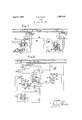
- Fig. 1 is adiagrammaticrepresentation of one embodiment of the presentinvention as applied to ,a stretch ofjrailway track provided with blocksignals;
- Fig, 2 sl1ows in a diagrammatic manner an application Of the embodimenteof the present invention as used for light-out relays.
- a stretch of railway ,track is showncornprising, the, exit endof a. track? sectlon A, the W Oleof a :trackvsection B, and the entrance endoia track section 0.
- atrack relay T is shown at the entr nc t0 'Itna ki QCt D Bi-having an associated track battery 4 located at the exit end .of the and track section; atuac-lcrelay located at t e ent ameiendiof the track section 0,
- polar relays D and D are located respectively. These polar relays are controlled over polarized circuits in accordance with the traflic conditions along the railway track in advance of the respective signal locations at which they are located.
- the relay R for example, includes a magnetic circuit made up of two core members 6 and 7 interconnected by a back strap 8, said magnetic circuit having associated therewith an armature 9 for operating the usual contacts.
- Coils 10 and 11 are wound oppositely on the cores 6 and 7 respectively.
- the lower terminals of these coils are connected, while the upper terminals of these coils are connected in series through two rectifier units 12 and 13, which allow current to pass only in the directions indicated by the arrow heads in the drawings. ⁇ Vith such connections, the coils 10 and 11 are alternately energized when the polarity of the applied current is reversed. Also, the windings are so placed on the cores that such alternate energization always produces magnetic, flux in the magnetic circuit in the same direction.
- an energizing circuit is completed for the polar relay D and the neutral relay B so long as the track relay T remainsenergized.
- This energizing circuit may be traced as follows :from the positive terminal of a suitable source of electrical potential indicated as B+,- through front contact 18 of relay R wire 19, front contact 20 of track relay T wire 21, windings of relay D wire-22, winding 10 of relay R rectifier unit'12, wire 23, front con,- tact 24 of relay R ,-to the negative terminal of the suitable source indicated as B'.
- the eontacts of relays D and R are caused to be in energized positions. It i's here notedthat the relays "D and R are energized over similar control circuits.
- the armature 9 of the relayR is suppli'ed with suitable contacts as diagrammatically 'lil lzESGH'E-Gd. These contacts control the elec signal S is thus caused to give its least restrictive indication.
- th signal S is displaying the green or unest-rictive indication as above explained to allow the train to pass.
- the track relay T is shunted thereby opening the energizing circuit of the relays D and P3 its front contact 20.
- the relav R is deenergized the incandescent bulb in the green indication means G of signal S is deenergized and the incandescent bulb in the red indication means R- is energized from the positive terminal of a suitable source of electrical potential indicated as 13+ through hack contact 9 of relay R Wire 31, through the incandescent bulb of the red indicating means R of signal S, to the negative terminal of the suitable source indicated as B-.
- the train proceeds to the signal S which is disolaying a greenindicat-ion allowing the rai l to pass onto track section C.
- the track relay T is deenergized its front cont-act 32 opens the energizing circuit of the relays D and R thereby causing the incandescentbulb of the green indicating means G of the signal S to be deenergized and the incandescent bulb of the red indicating means'll to he energized from the positive terminal of a suitable source of electrical potential indicated as 13+, through hacl; contact 33 of relay t wire 3 incandescent bulb of the red indicating means R of signal S to the negative terminal of the suitable source indicated 13-
- the decnergization of the relay R causes the polarity normally applied to the relays D and R to bereversed.
- This application of energy of reverse polarity is accomplished as soon as the train entiray leaves the track section B allowing front contact 20 of relay T to assume an energized position[
- This energizing circuit is traced as follows2-- from the positive terminal of a suitable source of electrical potential indicated as 13+, through back contact 2% ofrelay R wire 23, rectifier 13, winding 11 of relay R wire 22, windings of relay D wire 21, front Contact 20 of relayT wire 19, back contact 18 of relay R to the negative terminal of the suitable source indicated as B-.
- the application of reverse polarity to the relay D causes its polar contact 27 to assumea left-hand dotted line position as wellas causing the contacts of relay l? to also assume energized positions.
- the track relay T is energized allowing the relays D and R to be energized with a reverse polarity causing the incandescent bulb of the yellow indicating means Y of signal S to be energized in a r-lllllllill manner as already explained for signal S
- the energization of relay R again places normal polarity upon the energizing circuit of the relays D and R
- the application of normal polarity on the relay D causes the polar contact 27 to return to a normal full line position.
- the incandescent bulb of the red indication means of the signal S were controlled from a neutral contact on the relay D instead of by the neutral contact 9 of the relay ll, it would be momentarily energized upon :11 moving from one extreme position to the other causing a false indication to be momenhirily displayed. This would be true no matter how quickly the polarity of the applied potential to the relay 1) was reversed, as the magnetic flux in the core of a polar-neutral relay must pass through a zero value before it can build up with a new polarity. At the time that the magnetic flux in a relay core passes through a zero value, the neutral armature is caused to be operated to a deenergized position. T he addition of various means and devices for causing the slow operation of :uieh a polar-neutral relay still does not eliminate the operation of the neutral armature to a decnergized position as the magnetic flux value passes through zero.
- the incandescent bulb of the rod indie :ing means oi the signals S and S are go ter-mid oy contacts on their respective neutral relays R and R
- These relays R and ll do not drop their neut 'al arlnatures upon the reversal of polarity, as the application of verse polarity only causes the energization ot' the normally energized coil on each relay and at the same time causes the deenergiza- 2mm: oi the other coil on each relay.
- These two energizing coils on the R relays are so l that the magnetic flux produced by u with current flowing as determined a the respective rectifier units, always flows in the same direition in the magnetic circuit.
- the magnetic flux in a particular relay core does have to pass through a zero value when opposite polarity is applied, but is allowed to decrease at a normal time rate according to the inductance the c. cuit during such change in polarity, until the opposite winding has been energized.
- its the magnetic flux produced by each of these coils is in the same direction or of the same polarity, there is a certain amount of residual magnetism in the core after any particula r deeuergization which serves to eliminate the actual occurrence of a zero value of flux in the relay core.
- the rate of decrease of the flux in the relay core may be varied in the usual way to provide that it may not assume such a small value as to allow the armature of the relay to drop before the opposite coil is suiliciently energ ..cd to hold the a mature in an energized position.
- the relay embodying the pres- BLJ invention is shown as used for a lightout relay operable on either alternating current or du' ct current.
- This application of the embodiment oi the present invention is shown as employed with a signal location similarly controlled as the signal location S in Fig. 1 of the accom ninying drawings.
- Fig. 2 shows track sections A and B of 1 1 replaced by track sections A and B; signal S replaced by signal S; track relay T replaced by track relay T polar relay D replaced by polar relay D; relay R replaced by relay R; rectifier units 12 and 13 replaced by rectifier units 12 and 13*; and control wires 19 and 28 replaced by control wires 19 and 23 respectively.
- the signal S is supplied with electrical energy either from an alternating current ransmission line through a local transformer TB or from a local battery source ET.
- a power-off relay PO is associated with the local tr ns' ormer TR being connected directly cross the secondary winding of the transformer. It is obvious that the power-oil relay PO will be energized at all times that the alternating current transmission line is sup plied with power. This energization of the relay PO causes alternatingcurrcnt to be applied to the control circuits of the signal 3 through a front contact on the power-off relay, while if the relay is deenergized due to an alternating current power failure, direct current is supplied from the battery source BT through a back contact on t 1e relay PO.
- Two light-outrelays L and L0 are associated with the control circuits of the inclicating means of signal S
- These light-out relays have associated therewith rectifier units 3 8 and 39, also and l1 respectively, and are constructed in a similar manner as explained for the R relay with the additional feature that, the resistance and impedance of the windings must be so proportioned, that the currents, which flow when either direct current or alternating current is applied, will produce the same effective pull on the armatures.
- the impedance value will of course vary slightly according to the frequency of the alternati g current supply, which must of course be taken into consideration during the design of the relays for a particular application in practice. I s noted, however,
- Two resistances 43 and 4a are provided to compensate for the difference in resistance between the control circuits as determined by whether the light-out relays LO are energized or deenergized.
- the energizing circuitfor the incandescent bulb of the green indicating means G is traced as follows :from the lower terminal of the secondary of transformer TR, through wire 46, front contact 47 of the power-0E relay PO, wire 48, front contact 9 of relay R wire L9, polar contact 27 of relay I) in a light-out normal position, wires 50 and 51, rectifier unit 39, left-hand winding 52 of relay L0 wire 53, incandescent bulb of the green indicating means G of signal S, wires 54, 55 and 5-5, to the upper terminal of the secondary winding of the local transformer TR.
- the circuit for the relay L0 is opened causing its armature 58 to assume a deenergized position if the bulb in the green indicating means G burns out.
- the incandescent bulb of the yellow indicating means Y of signal S is energized through a circuit from the polar contact 2'! in a right-hand dotted line position, through wire 50, resistance 43,back
- incandescent bulb of the yellow indicating means Y of signal S to the wire 54 and through the circuit as heretofore traced.
- the display of the yellow indication which is a more restrictive or caution indication, insures that the engineer on the'train does not miss the signal location in passing and also that such indication, which is received, is on the side of safety;
- the negative terminal of, the battery BT is connected to the control circuits at the same point as the upper terminal of the secondary of local transformer TR, while the opposite terminal of the battery ET is connected through wire 61 to the back contact 47 of power-0E relay PO.
- the power-oil relay PO which is connected directly across the secondary of local transformer TR become energized, its back contact ll would allow direct current to be h applied from the battery Bl through the same energizing circuits heretofore ex plained.
- each of the LO relays embodying the present invcnti on only one of their windings would be energized when controlled by direct current depending upon the polarity at the relay terminals. This will not be pointed out in detail as the specific operation of the relay on direct current has been pointed out for Fig. l of the accompanying drawings.
- a relay embodying the present invention has been shown being useful in polarized direct current control circuits, and in circuits where both alternating and direct currents are used for controlling purposes.
- the present invention provides means for supplying a continuous unidirectional magnetic flux from an alternating current by use of two halfuvave rectitiei's and two windings having their magnetic circuits interconnected, said rectifier-s and said windings being bridge connected to produce a magnetic effect of a full-wave rectifier current.
- a stretch of railway track a plurality of signals governing traffic over said stretch of railway track, a polar relay located at each of said signals and operated over a polarized circuit governed by traific conditions in advance of the corresponding one of sig nals, a neutral relay having two windings connected in a multiple con'ibination, said multiple combination connected in series with said polar relay in said polarized circuit, one rectifier in series with one of said two windings, another rectifier in series with the other one of said two windings, means governing the relative restrictiveness of said signals, said means including said polar relay and said neutral relay, whereby the re strictiveness of said signals may be altered over said polarized circuit Without afi'ecting the position of said neutral relay.
- a light signal giving indications of varying restrictiveness, each indication having a control circuit, a light-out relay in each ct said control circuits for causing the indication next in order of restrictiveness to be given it the control circuit of a particular indication is opened, said light-out relay being operable on either direct current or alternating current, an electro-magnetic operating mechanism for said relay, and means providing said mechanism with the same efiective magnetic flux values whether said control circuits are supplied with direct or alternating currents.
- a color light signal giving a plurality of indications of varying restrictiveness
- an incandescent bulb for each indication
- each of said incandescent bulbs having a control circuit
- means for supplying said control circuits with either alternating current or direct current and a plurality of light-out relays each for causing one of said bulbs next in order of restrictiveness burns out
- said light-out relays including a magnetic circuit, two coils associated with said magnetic circuit, and two rectifier units, one connected in series combination with one of said coils, the other connected in a series combination with the other one of said coils, said two series combinations connected in a multiple combination, said multiple combination connected in series with its respective one of said control circuits of said incandescent bulbs.
Landscapes
- Engineering & Computer Science (AREA)
- Mechanical Engineering (AREA)
- Train Traffic Observation, Control, And Security (AREA)
Description
April 5, 1932. Q S HELD 1,852,406
RELAY Filed Feb. 13, 1950 Fae. 1.
RELAY Application filed February 13, 1930. Serial 119. 428,090.
This invention relates to electrically operated relays, and more particularly pertains to tractive type relays which are operable on either direct current or alternating current, and which are unresponsive to a reversal in polarity of the current supplied to their energizing circuits.
In some cases, it is desirable to operate relays over polarized circuits to thereby gain th advantages of the inherent cross protection 'leatures and the added number of controls provided thereby. The control ofathree indication railroad trailiccontrolling signal is one uch case. However, the use of the usual polar-neutral direct current relay, or the usual three position alternating current relay has a disadvantage in that the contacts of such relays must be operated to their deenergized positions in order to be operated to the opposite extreme positions selected by the application of energy of opposite polarity. is the deenergized position of such relays is used to cause the associated signals to display red or danger indications, a flashing of L red or danger indications is occasioned by the change from one restrictive indication to the other less restrictive indication.
Also, it is sometimes desirable to operate a relay at one ti me by alternating current, and
1: to operate it at another time by direct current. This is illustrated by the usual lightout relay employed With railway signals to cause a more restrictive indication tobe given should a particular incandescent bulb burn out. But. it generally understood that a relay operated on direct current gives more satisfactory results than the same relay operai'ml on alternating current.
With the above and other considerations in mind, it is proposed to provide in accord ance with the presentinvention, a relay device or arrangement which is operable on either alternating current or direct current and is unresponsive to a reversal ofpolarity oi" its energizing source in either case.
llrlnre specifically. it is proposed to n'ovide a neutral relay havingtwo windings each being connected in series with a half-Wave rectifier, With the two series combinations connected in multiple in such a way that, when threat current is applied t he mul iples ies comb nation, one ivindi gnf'th relay w l he ene gized, while if the appli d p larty ieters th her Winding withheeherglzed- Al o, wi h either one 0 the other of the W wh dinssenercg zed as det rmined by the series ec fi rs, the pola ity of the magnetic flux produced in the relay core :by the windings will be il csame either ase. It is obvious that such a combination will p o ride for the en rgizationtog the two ,Windte nately whe alte na ing current is supplie to th enmihalspf thenco jnbination.
Othe obi ct purposes and characteristic fea ures of he pre en invention will be in pa t obvious from the acc mpanying drawngs, and 1n pant pointedoutas glillQfClGSCIiP" n of the intentio progresses- In describing .the invention in detail reference will he made to the accompanying drawings, in which:
Fig. 1 is adiagrammaticrepresentation of one embodiment of the presentinvention as applied to ,a stretch ofjrailway track provided with blocksignals;
Fig, 2 sl1ows in a diagrammatic manner an application Of the embodimenteof the present invention as used for light-out relays.
Withreference to Fig. *1 ofztheaccompany- 11g drawings, a stretch of railway ,track is showncornprising, the, exit endof a. track? sectlon A, the W Oleof a :trackvsection B, and the entrance endoia track section 0. These blocksor track sections A,;B and Gare separated frorn eachotherby the usual insulated o nts; tvvitheach block .Qrtrack section supplied w th the usual track relay at its ent an rend an l the usuahtrackibattery at the (hilt end. the specific example shown :in Fig. 1, atrack relay T is shown at the entr nc t0 'Itna ki QCt D Bi-having an associated track battery 4 located at the exit end .of the and track section; atuac-lcrelay located at t e ent ameiendiof the track section 0,
a so havingrassociated therewith a suitable i track batterylnot shown) and a track battery 5 located at the exit end of track section A. A the en anc o th tr ck secti ns 1B andiGiar leca ed s gnals r and i S resp chw y, w ich ar r presented a three :indication color light signals giving red, yellow and green indications. These indications have the usual significance with each indication being produced by the energization of an electric incandescent bulb or lamp located so that its light rays pass through a suitable color screen and such other optical means as may be required.
At the signal locations, polar relays D and D are located respectively. These polar relays are controlled over polarized circuits in accordance with the traflic conditions along the railway track in advance of the respective signal locations at which they are located.
Two neutral relays R and R constructed according to the present invention, are lo cated respectively at the signal locations S and S The relay R for example, includes a magnetic circuit made up of two core members 6 and 7 interconnected by a back strap 8, said magnetic circuit having associated therewith an armature 9 for operating the usual contacts.
Let us consider that trafiic conditions in advance of signal S are such that the polar relay D and neutral relay R are in energized conditions. Thus, an energizing circuit is completed for the polar relay D and the neutral relay B so long as the track relay T remainsenergized. This energizing circuitmay be traced as follows :from the positive terminal of a suitable source of electrical potential indicated as B+,- through front contact 18 of relay R wire 19, front contact 20 of track relay T wire 21, windings of relay D wire-22, winding 10 of relay R rectifier unit'12, wire 23, front con,- tact 24 of relay R ,-to the negative terminal of the suitable source indicated as B'. With this energizing circuit completed, the eontacts of relays D and R are caused to be in energized positions. It i's here notedthat the relays "D and R are energized over similar control circuits.
I The armature 9 of the relayR is suppli'ed with suitable contacts as diagrammatically 'lil lzESGH'E-Gd. These contacts control the elec signal S is thus caused to give its least restrictive indication.
if a train approaches the track section B, th signal S is displaying the green or unest-rictive indication as above explained to allow the train to pass. As soon as the train actually passes onto the track section B, the track relay T is shunted thereby opening the energizing circuit of the relays D and P3 its front contact 20. As soon as the relav R is deenergized the incandescent bulb in the green indication means G of signal S is deenergized and the incandescent bulb in the red indication means R- is energized from the positive terminal of a suitable source of electrical potential indicated as 13+ through hack contact 9 of relay R Wire 31, through the incandescent bulb of the red indicating means R of signal S, to the negative terminal of the suitable source indicated as B-.
The train proceeds to the signal S which is disolaying a greenindicat-ion allowing the rai l to pass onto track section C. As soon as the track relay T is deenergized its front cont-act 32 opens the energizing circuit of the relays D and R thereby causing the incandescentbulb of the green indicating means G of the signal S to be deenergized and the incandescent bulb of the red indicating means'll to he energized from the positive terminal of a suitable source of electrical potential indicated as 13+, through hacl; contact 33 of relay t wire 3 incandescent bulb of the red indicating means R of signal S to the negative terminal of the suitable source indicated 13- The decnergization of the relay R causes the polarity normally applied to the relays D and R to bereversed. This application of energy of reverse polarity is accomplished as soon as the train entiray leaves the track section B allowing front contact 20 of relay T to assume an energized position[ This energizing circuit is traced as follows2-- from the positive terminal of a suitable source of electrical potential indicated as 13+, through back contact 2% ofrelay R wire 23, rectifier 13, winding 11 of relay R wire 22, windings of relay D wire 21, front Contact 20 of relayT wire 19, back contact 18 of relay R to the negative terminal of the suitable source indicated as B-. The application of reverse polarity to the relay D causes its polar contact 27 to assumea left-hand dotted line position as wellas causing the contacts of relay l? to also assume energized positions.
The .energization of these relays I) and R cause the-energization of the incandescent bulb of the yellow indii'wating means Y of the signal S This energizing circuit is traced as follows :-from the positive terminal of a suitable source of electrical potential indicated as 13+, through front contact 9 of relay R wire 26, polar contact in a dotted line position, wire 36, through the incandescent bulb of the yellow indicating means Y of the signal S to the negative terminal of the suitable source indicated as 3-.
i l hen the train leaves the track section C and passes onto the next track section in ad Vance (not shown), the track relay T is energized allowing the relays D and R to be energized with a reverse polarity causing the incandescent bulb of the yellow indicating means Y of signal S to be energized in a r-lllllllill manner as already explained for signal S The energization of relay R again places normal polarity upon the energizing circuit of the relays D and R The application of normal polarity on the relay D causes the polar contact 27 to return to a normal full line position.
ll the incandescent bulb of the red indication means of the signal S were controlled from a neutral contact on the relay D instead of by the neutral contact 9 of the relay ll, it would be momentarily energized upon :11 moving from one extreme position to the other causing a false indication to be momenhirily displayed. This would be true no matter how quickly the polarity of the applied potential to the relay 1) was reversed, as the magnetic flux in the core of a polar-neutral relay must pass through a zero value before it can build up with a new polarity. At the time that the magnetic flux in a relay core passes through a zero value, the neutral armature is caused to be operated to a deenergized position. T he addition of various means and devices for causing the slow operation of :uieh a polar-neutral relay still does not eliminate the operation of the neutral armature to a decnergized position as the magnetic flux value passes through zero.
However, in accordance with the present invention, the incandescent bulb of the rod indie :ing means oi the signals S and S are go ter-mid oy contacts on their respective neutral relays R and R These relays R and ll do not drop their neut 'al arlnatures upon the reversal of polarity, as the application of verse polarity only causes the energization ot' the normally energized coil on each relay and at the same time causes the deenergiza- 2mm: oi the other coil on each relay. These two energizing coils on the R relays are so l that the magnetic flux produced by u with current flowing as determined a the respective rectifier units, always flows in the same direition in the magnetic circuit.
In other words, the magnetic flux in a particular relay core does have to pass through a zero value when opposite polarity is applied, but is allowed to decrease at a normal time rate according to the inductance the c. cuit during such change in polarity, until the opposite winding has been energized. its the magnetic flux produced by each of these coils is in the same direction or of the same polarity, there is a certain amount of residual magnetism in the core after any particula r deeuergization which serves to eliminate the actual occurrence of a zero value of flux in the relay core. It is noted that the rate of decrease of the flux in the relay core may be varied in the usual way to provide that it may not assume such a small value as to allow the armature of the relay to drop before the opposite coil is suiliciently energ ..cd to hold the a mature in an energized position.
lVith the normal polarity now applied to the relays D and It, the signal S is caused to a green indication. \Vhen the train gr es onto the second track section in ad is oi the signal .S", signal S iscau-sed .to give a clear or green indication, in a similar manner as explained for signal S lVith reference to 2056 the accompanydrawings, the relay embodying the pres- BLJ invention is shown as used for a lightout relay operable on either alternating current or du' ct current. This application of the embodiment oi the present invention is shown as employed with a signal location similarly controlled as the signal location S in Fig. 1 of the accom ninying drawings. Thus, it deemed unnecessary to explain the various controls that are governed in accord ance with traffic conditions. Also, the Various devices and the various circuits; in Fig. 2 which are similar to those of F l are (lesi. nated with the same reference clniracters having distinctive exponents a. More specifically, Fig. 2 shows track sections A and B of 1 1 replaced by track sections A and B; signal S replaced by signal S; track relay T replaced by track relay T polar relay D replaced by polar relay D; relay R replaced by relay R; rectifier units 12 and 13 replaced by rectifier units 12 and 13*; and control wires 19 and 28 replaced by control wires 19 and 23 respectively.
The signal S is supplied with electrical energy either from an alternating current ransmission line through a local transformer TB or from a local battery source ET. A power-off relay PO is associated with the local tr ns' ormer TR being connected directly cross the secondary winding of the transformer. It is obvious that the power-oil relay PO will be energized at all times that the alternating current transmission line is sup plied with power. This energization of the relay PO causes alternatingcurrcnt to be applied to the control circuits of the signal 3 through a front contact on the power-off relay, while if the relay is deenergized due to an alternating current power failure, direct current is supplied from the battery source BT through a back contact on t 1e relay PO.
Two light-outrelays L and L0 are associated with the control circuits of the inclicating means of signal S These light-out relays have associated therewith rectifier units 3 8 and 39, also and l1 respectively, and are constructed in a similar manner as explained for the R relay with the additional feature that, the resistance and impedance of the windings must be so proportioned, that the currents, which flow when either direct current or alternating current is applied, will produce the same effective pull on the armatures. The impedance value will of course vary slightly according to the frequency of the alternati g current supply, which must of course be taken into consideration during the design of the relays for a particular application in practice. I s noted, however,
' that the direct current resistance 1111C the alternating current impedance will not have the usual relationship due to the absence of a reversal of magnetic flux in the relay core.
Two resistances 43 and 4a are provided to compensate for the difference in resistance between the control circuits as determined by whether the light-out relays LO are energized or deenergized.
The control circuits of the signal S will now be explained considerin only those circuits which are different from Fig. 1 and more specifically as determined by the governing control of the contacts 9 and 27 of the relays R and D respectively.
Considering that the alternating current transmission lines supplied with suitable alternating current potential which the local transformer TB in turn supplied to the power-off relay PO, and that the traflic controlling part of the system is suchthat the incandescent bulb of the green indicating means G of the signal S should be energized, the energizing circuitfor the incandescent bulb of the green indicating means G is traced as follows :from the lower terminal of the secondary of transformer TR, through wire 46, front contact 47 of the power-0E relay PO, wire 48, front contact 9 of relay R wire L9, polar contact 27 of relay I) in a light-out normal position, wires 50 and 51, rectifier unit 39, left-hand winding 52 of relay L0 wire 53, incandescent bulb of the green indicating means G of signal S, wires 54, 55 and 5-5, to the upper terminal of the secondary winding of the local transformer TR. This is the energizing circuit for the incandescent bulb of thegreen indicating means G of the signal S as normally supplied with alternating current. It is of course understood. that on one half of the alternating current cycle that current flows through the circuit in the direction traced, but on the other half of the cycle the current flows in a reverse direction, thus including the. right-hand coil 57 of relay L0 and rectifier unit 38 in place of the left-hand coil 52 and rectifier unit 39. From this explanation, it is obvious that the coils 52 and 57 are alternately energized with the application of alternating current. Also, as the coils are so wound and the rectifier units so connected that the currents which flow in the coils each produce magnetic flux in the relay core in the same direction or of the same polarity. Since this is true, a continuous uni-directional flux is produced in the magnetic circuit of the relay L0 which has no zero value due to the combination of the arrangement of coils and rectifiers, and also due to the fact that the reversal of polarity does not cause the residual magnetism to be reduced to zero before the opposite polarity is built up.
As the signal S is supplied with an incandescent bulb for each indicating means, the circuit for the relay L0 is opened causing its armature 58 to assume a deenergized position if the bulb in the green indicating means G burns out. With the armature 58 of relay L0 deenergized, the incandescent bulb of the yellow indicating means Y of signal S is energized through a circuit from the polar contact 2'! in a right-hand dotted line position, through wire 50, resistance 43,back
incandescent bulb of the yellow indicating means Y of signal S, to the wire 54 and through the circuit as heretofore traced.
As the green indication of signal S represents a clear signal for allowing traflic to pass normal speed, the display of the yellow indication, which is a more restrictive or caution indication, insures that the engineer on the'train does not miss the signal location in passing and also that such indication, which is received, is on the side of safety;
Should the polarcontact27 be in a lefthand dotted line position for controlling the energizing circuit of the incandescent bulb in the yellow indicating means Y of signal S for a given trafiic condition as explained for descent bulb of the red indicating means R, 1f the signal from the incandescent bulb for the yellow indicating means Y which burns out, all of which is accomplished in a similar manner as explained for the relay L0".
The negative terminal of, the battery BT is connected to the control circuits at the same point as the upper terminal of the secondary of local transformer TR, while the opposite terminal of the battery ET is connected through wire 61 to the back contact 47 of power-0E relay PO. Thus, it is obvious that should the power-oil relay PO which is connected directly across the secondary of local transformer TR become energized, its back contact ll would allow direct current to be h applied from the battery Bl through the same energizing circuits heretofore ex plained. In the case of each of the LO relays embodying the present invcnti on, only one of their windings would be energized when controlled by direct current depending upon the polarity at the relay terminals. This will not be pointed out in detail as the specific operation of the relay on direct current has been pointed out for Fig. l of the accompanying drawings.
Thus, a relay embodying the present invention has been shown being useful in polarized direct current control circuits, and in circuits where both alternating and direct currents are used for controlling purposes.
In brief, the present invention provides means for supplying a continuous unidirectional magnetic flux from an alternating current by use of two halfuvave rectitiei's and two windings having their magnetic circuits interconnected, said rectifier-s and said windings being bridge connected to produce a magnetic effect of a full-wave rectifier current.
Having described a relay combination as one specific embodiment of the present invention and two applications in which such a relay combination may be used, it is desired to be understood that the combination selected and the applications shown are to facilitate in the disclosure of the invention rather than to limit the number of forms which the invention may assume; and, it is to be further understood that various modifications, adaptations and alterations may be applied to the specific embodiment shown to meet the requirements of practice without in any manner departing from the spirit or scope of the invention except as limited by the appended claims.
Having described my invention, I now claim:
1. In a tral'lic controlling system for railroads, a stretch of railway track, a plurality of signals governing traffic over said stretch of railway track, a polar relay located at each of said signals and operated over a polarized circuit governed by traific conditions in advance of the corresponding one of sig nals, a neutral relay having two windings connected in a multiple con'ibination, said multiple combination connected in series with said polar relay in said polarized circuit, one rectifier in series with one of said two windings, another rectifier in series with the other one of said two windings, means governing the relative restrictiveness of said signals, said means including said polar relay and said neutral relay, whereby the re strictiveness of said signals may be altered over said polarized circuit Without afi'ecting the position of said neutral relay.
2. In a trafiic controlling system for railroads, a light signal giving indications of varying restrictiveness, each indication having a control circuit, a light-out relay in each ct said control circuits for causing the indication next in order of restrictiveness to be given it the control circuit of a particular indication is opened, said light-out relay being operable on either direct current or alternating current, an electro-magnetic operating mechanism for said relay, and means providing said mechanism with the same efiective magnetic flux values whether said control circuits are supplied with direct or alternating currents.
3. In a traffic controlling system for railroads, a color light signal giving a plurality of indications of varying restrictiveness, an incandescent bulb for each indication, each of said incandescent bulbs having a control circuit, means for supplying said control circuits with either alternating current or direct current, and a plurality of light-out relays each for causing one of said bulbs next in order of restrictiveness burns out, said light-out relays including a magnetic circuit, two coils associated with said magnetic circuit, and two rectifier units, one connected in series combination with one of said coils, the other connected in a series combination with the other one of said coils, said two series combinations connected in a multiple combination, said multiple combination connected in series with its respective one of said control circuits of said incandescent bulbs.
In testimony whereof I aliix my signature.
OSCAR S. FIELD.
Priority Applications (1)
| Application Number | Priority Date | Filing Date | Title |
|---|---|---|---|
| US428090A US1852406A (en) | 1930-02-13 | 1930-02-13 | Relay |
Applications Claiming Priority (1)
| Application Number | Priority Date | Filing Date | Title |
|---|---|---|---|
| US428090A US1852406A (en) | 1930-02-13 | 1930-02-13 | Relay |
Publications (1)
| Publication Number | Publication Date |
|---|---|
| US1852406A true US1852406A (en) | 1932-04-05 |
Family
ID=23697507
Family Applications (1)
| Application Number | Title | Priority Date | Filing Date |
|---|---|---|---|
| US428090A Expired - Lifetime US1852406A (en) | 1930-02-13 | 1930-02-13 | Relay |
Country Status (1)
| Country | Link |
|---|---|
| US (1) | US1852406A (en) |
Cited By (1)
| Publication number | Priority date | Publication date | Assignee | Title |
|---|---|---|---|---|
| DE10110032C1 (en) * | 2001-03-01 | 2002-10-24 | Julius Berger Gmbh & Co Kg | Spring-loaded blade for pocket knife has shaped projection on opposite side of hinge from cutting portion of blade, bearing against free end of leaf spring |
-
1930
- 1930-02-13 US US428090A patent/US1852406A/en not_active Expired - Lifetime
Cited By (1)
| Publication number | Priority date | Publication date | Assignee | Title |
|---|---|---|---|---|
| DE10110032C1 (en) * | 2001-03-01 | 2002-10-24 | Julius Berger Gmbh & Co Kg | Spring-loaded blade for pocket knife has shaped projection on opposite side of hinge from cutting portion of blade, bearing against free end of leaf spring |
Similar Documents
| Publication | Publication Date | Title |
|---|---|---|
| US1704736A (en) | Railway-traffic-controlling apparatus and electrical apparatus suitable for use therein | |
| US1852406A (en) | Relay | |
| US2461452A (en) | Code detecting means | |
| US2117820A (en) | Electrical relay | |
| US2141803A (en) | Railway traffic controlling apparatus | |
| US2515868A (en) | Coded track circuit apparatus | |
| US2168816A (en) | Railway signaling | |
| US2122373A (en) | Signaling system for railroads | |
| US2280491A (en) | Absolute permissive block system of railway signaling | |
| US1790524A (en) | Railway-signaling system | |
| US1822497A (en) | Railway traffic controlling apparatus | |
| US2318542A (en) | Railway signaling system | |
| US2122382A (en) | Signaling system for railroads | |
| US2409044A (en) | Railway signaling apparatus | |
| US2222804A (en) | Railway signaling apparatus | |
| US2367742A (en) | Railway track circuit apparatus | |
| US1667577A (en) | Railway-traffic-controlling apparatus | |
| US1584991A (en) | Railway signaling | |
| US2888553A (en) | Railway block signaling apparatus | |
| US1520072A (en) | Railway signaling | |
| US1856754A (en) | Railway traffic controlling apparatus | |
| US2105260A (en) | Railway signaling | |
| US2136808A (en) | Railway traffic controlling apparatus | |
| US2559391A (en) | Coded signaling apparatus | |
| US2038094A (en) | Railway signaling system |