US1852396A - Wire bending machine - Google Patents
Wire bending machine Download PDFInfo
- Publication number
- US1852396A US1852396A US471139A US47113930A US1852396A US 1852396 A US1852396 A US 1852396A US 471139 A US471139 A US 471139A US 47113930 A US47113930 A US 47113930A US 1852396 A US1852396 A US 1852396A
- Authority
- US
- United States
- Prior art keywords
- wire
- coil
- machine
- pedal
- chuck
- Prior art date
- Legal status (The legal status is an assumption and is not a legal conclusion. Google has not performed a legal analysis and makes no representation as to the accuracy of the status listed.)
- Expired - Lifetime
Links
- 238000005452 bending Methods 0.000 title description 11
- 238000005520 cutting process Methods 0.000 description 7
- 230000000994 depressogenic effect Effects 0.000 description 7
- 238000009941 weaving Methods 0.000 description 2
- 241000283690 Bos taurus Species 0.000 description 1
- 230000004308 accommodation Effects 0.000 description 1
- 229940000425 combination drug Drugs 0.000 description 1
- 239000010730 cutting oil Substances 0.000 description 1
- 238000003780 insertion Methods 0.000 description 1
- 230000037431 insertion Effects 0.000 description 1
- 230000002093 peripheral effect Effects 0.000 description 1
- 238000004804 winding Methods 0.000 description 1
Images

Classifications
-
- B—PERFORMING OPERATIONS; TRANSPORTING
- B21—MECHANICAL METAL-WORKING WITHOUT ESSENTIALLY REMOVING MATERIAL; PUNCHING METAL
- B21F—WORKING OR PROCESSING OF METAL WIRE
- B21F27/00—Making wire network, i.e. wire nets
- B21F27/02—Making wire network, i.e. wire nets without additional connecting elements or material at crossings, e.g. connected by knitting
- B21F27/04—Manufacturing on machines with rotating blades or formers
Definitions
- the present invention has relation to Wire enough for the wire hook, 10, to pass into bending machinery and refers more particuthe chuck and tobe carried through the entire larly to a machine for forming wire netting helix ofth'e groove. lVhen the opposite edge for use in mattress springs, fences and other of the arbor reaches the notch of the chuck,
- the generalobject of my invention is to and this bend is drawn into the notch and provide a simple and inexpensive machine cathrough-the groove. pable of forming wire netting at high speed. in this manner a flattened coil of wire is More particularly my object is the provision shot through the machine at high speed.
- Fig. 5 shows, 011 a larger scale, details this pull is utilized to move the web forward of the wire cutting mechanism of the device. step by step, every time a coil is finished.
- rind Fig.6 illustrates a modified shape of Below the roller, 13, is hung a shaft, 14, on forming .hor. which 1s shown fastened a series of three 011 the frame of the machine is mounted a pointed, star-shaped stops, 15, and a second 30 short spindle l for continuous rotation by a Series of similar stops, 16. All these stops B0 prime mover, such as an electric motor 2.
- The are preferably alike but one series is advanced inner end of this spindle is slotted to receive relative to the other, so that the points of one a knife shaped arbor 3, which travels in a series ofstars are positioned in line with the guide, or chuck i, and this chuck is firmly 601F661 f W9 betwen the Points of the 35 clamped in iti 011 th hi fra other series.
- This relat1on is best shown in b means f a it bl Cap 5, Figure 4.
- this shaft is placed a reel 6, on which a spool of wire, is given a onesixth revolutlon after the wire 'Z, is shown deposited.
- This wire is bent over 0011 has been cut, allowing the wire web to 0 a series of pulleys, 8, and over a pulley 9, be advancedgby the pull of. thereel, 12, until from which the wire is carried to the chuck, caught onthe points of the star series, 16, -l,the end of the wire having previously been which by this time have taken the position bent into the shape of a hook, 10. formerly held by .the series, 15.
- the web The chuck is made with an internal helical ccmes to a stop in thisposition and the magroove, 4*, in continuation of a notch, 1, as chine is againstarted towind anew coil. best shown in Figure 3.
- this The mechanismishown in the drawings, for hook, 10, is placed over one edge of the arbor advancing the web will now be described. and pushed into the notch, 4", whereupon the Near the bottom of the machine frame is hung machine is started.
- the arbor fits the chuck a pedal, 25, which by a rod, 26, is connected to snugly, but the groove, 4', affords room oscillate a bell crank, 27, carrying a pawl, 28,
- the mechanism for cutting the wire each time a new coil is completed is shown to comprise a pair of slides, 35, 36, suitably mounted in guides of the machine frame in a continued alinement and shaped at their p posed ends with V-shaped cutting notches, 37, 38, as best shown in Figure 5. These slides are perforated to receive a pair of levers, 39, 40, which latter are hung on a pivot, 41,
- a second pedal, 47 which through the medium of a rod, 48, and bell crank, 49, is connected to throw a clutch member, 50, into engagement with a cone 51, of a driven pulley, 52.
- the latter is, by means 1 of a belt, 53, connected for operation by the motor, 2.
- the pulley, 52 is mounted on a counter shaft, 54, to which is aflixed a pulley or sprocket wheel, 55, connected by a belt or chain, 56, with a pulley or sprocket, 57, of the spindle, 1.
- the pedal, 47 is connected to engage the driving clutch to start the machme.
- On the pedal lever, 47 is mounted a projection,
- a brake pulley, 7 0, On the spindle is mounted a brake pulley, 7 0, on which a brake band, 71, is shown riding, and the latter is, through the medium of a rod, 72, and lever, 73, connected to be released from the drum, 70, when the pedal, 47, is depressed.
- a suitable powerful spring, 74 is shown employed to set the brake when the solenoid is energized to release the pedal.
- slipjoint between the reel, 12, and its driving mechanism in order to compensate for the increasing diameterof the finishedroll of nettin and the conse uent increasin e-, c This may be accomplished ripheral speed. in any suitable, Well known manner.
- slip-joint is indicated by a pair of co-acting friction disks, 20, 21.
- the wire used for some purposes is more resilient than other uses require, and some coils may be flatter than others. For these reasons the wire leaving the arbor will, at times, rebound more or less, with the result that the new coil, being formed, is thrown out of line with the finished coil it is required to engage. This condition may be readily overcome by employing an arbor which is more or less twisted forward, in direction of the helix angle, as indicated in Figure 3.
- the arbor and the chuck are readily removable, and must be changed when a different size or pitch of coil is required.
- the star shaped stops 15, and 16, must also be adjusted axially, when the linear pitch of the coil is changed.
- the frame, 22, on which the guide rollers, 8, aremounted, is shown hung on a pivotal stud, 23, and it is free to swing, to adjust'itself to the size of the wire ,coil, 7.
- the mechanism for rotating the reel, 12, is shown to comprise a disc, 81, driven by a belt, 82, from a pulley (not shown) on the spind e, 1. 9n the face of the disc is mounted a stud, 83, from which a rod, 84, extends to a lever, 85, carrying a pawl, 86, and this pawl engages a ratchet wheel, 87, of the friction disc, 21.
- a pawl, 88 is provided to prevent backlash of the ratchet wheel.
- the mechanism required for supporting the first coil may be merely a bar, 90, which is pushed through the first coil, whereupon strings or wires, 91, are tied to or hooked into this bar and fastened to the winding reel. Or any other suitable means may be employel.
- a wire bending machine the combination with a driving arbor and a forming chuck, of means for guiding wire to said arbor and chuck, means for supporting each completed coil, a pedal mechanism for cutting oil each completed coil and connected to rotate said supporting means to advance the coils and to shift them axially, and a reel yieldingly rotated for accommodation of the finished coils.
- a wire bending machine the combination with a chuck having an internal helical groove and arbor fitted to rotate within said chuck for the purpose of making coils of wire, of a reel yieldingly rotated to receive the finished coils of wire, a shaft having star pointed stops for holding the finished coils in position While a new coil is being wound, and a pedal mechanism for cutting off each finished coil, for partly rotating said shaft to advance the finished coils and for moving the shaft axially one half the linear pitch of the coil in order to position the finished coil.
- a wire bending machine In a wire bending machine, the combination with a grooved chuck and an arbor fitted to rotate within said chuck for the purpose of driving wire through the chuck and to form it into a coil, a depressible pedal connected to start the machine to rotate said arbor, a pawl for holding the pedal depressed, a solenoid magnet for withdrawing said pawl from the pedal, and a switch operable by the coil issuing from said chuck to close a circuit throlugh said magnet to withdraw the said paw 4.
- a wire bending machine In a wire bending machine, the combination with means for forming coils of wire, of a reel yieldingly rotatable to receive the finished coils, a shaft having star pointed stops for holding the finished coils in position while each new coil is being formed, said stops being axially adjustable to suit the linear pitch of the coils, and means for partly rotating said shaft to advance the finished coils and simultaneously to move the shaft axially one-half the linear pitch of the coils in order to position the last finished coil to receive the coil to be formed.
- a wire bending machine the combination with means for forming and weaving coils of wire, a clutch, a brake, a pedal depressible to operate the clutch to start the machine and simultaneously to release the brake, means to lock the pedal in depressed position, and means actuated by each projected coil to release said locking means.
- the combi nation with means for forming and weaving coils of wire, a reel yieldingly rotatable to receive the finished netting, a shaft, a series of star pointed stop members on said shaft, said members being axially adjustable to engage and to hold in position each finished coil while a new coil is being wound, a drum on said shaft, a stationary member riding in a zigzag peripheral groove of said drum, and means connected to impart step by step rotation to said shaft to advance the finished netting and simultaneously to shift the shaft axially one-half the linear pitch of the coils.
Landscapes
- Engineering & Computer Science (AREA)
- Manufacturing & Machinery (AREA)
- Textile Engineering (AREA)
- Mechanical Engineering (AREA)
- Wire Processing (AREA)
Description
April 5, 1932- F. BERGANDI 1,852,396
WIRE BENDING MACHINE Filed July 28, 1930 2 Sheets-Sheet 1 vi-gm INVENTOR.
A TTORNEK 1932, F. BERGANm WIRE BENDING MACHINE Filed July 28, 1930 2 Sheets-$heet 2 INVENTOR: 17km? zev BY A TTORNEY Il mu fillllillllliilik Patented Apr. 5, 1932 1,852,396
UNITED STATES PATENT OFFICE FRANK BERGANDI, LOS ANGELES, CALIFORNIA WIRE BENDING MACHINE Application filed July 28, 1930. Serial No. 471,139.
The present invention has relation to Wire enough for the wire hook, 10, to pass into bending machinery and refers more particuthe chuck and tobe carried through the entire larly to a machine for forming wire netting helix ofth'e groove. lVhen the opposite edge for use in mattress springs, fences and other of the arbor reaches the notch of the chuck,
devices employing wire nettin a second bend in the wire has been completed,
The generalobject of my invention is to and this bend is drawn into the notch and provide a simple and inexpensive machine cathrough-the groove. pable of forming wire netting at high speed. in this manner a flattened coil of wire is More particularly my object is the provision shot through the machine at high speed.
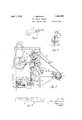
10 of means for forming wire netting in continhen the desired length of coil is produced uous rolls of various widths. These and the the wire is cut close to the arbor as will herefurther objects and advantages of my invenmatter be explained. The coil is now held tion are hereinafter fully described and illusin a suitablemanner, and the machine which tratcd in the appended drawings, of which: has been stopped long enough to hang the I Fig. l is a front elevation of a machine coil,again started and anew coil is formed. embodying the invention and with parts bro- The relation of the new coil tothe old is ken away for the sake of clearncss. Flg. 211s such, that the new bend, 10, automatically an end elevation of the device substantially hooks into the first bend of the old coil, then in agreement with Fig. 1 and in this view into the seco1 1d,a11d so forth to the end, when 20 several parts have also been broken away in the wire again is cut. Behind the machine is order to disclose the interior mechanism. mount-ed a reel, .12. As the netting web Fig. 3 is a detailed view illustrating the wire grows longer, it is bent over a roller, 18, and forming elements of the structure. Fig. 4 fastened to this reel. The latter is constantly illustrates a detail of the wire feeding mechabe ng rotated, causing a pull on the web, and
555 nism. Fig. 5 shows, 011 a larger scale, details this pull is utilized to move the web forward of the wire cutting mechanism of the device. step by step, every time a coil is finished. rind Fig.6 illustrates a modified shape of Below the roller, 13, is hung a shaft, 14, on forming .hor. which 1s shown fastened a series of three 011 the frame of the machine is mounted a pointed, star-shaped stops, 15, and a second 30 short spindle l for continuous rotation by a Series of similar stops, 16. All these stops B0 prime mover, such as an electric motor 2. The are preferably alike but one series is advanced inner end of this spindle is slotted to receive relative to the other, so that the points of one a knife shaped arbor 3, which travels in a series ofstars are positioned in line with the guide, or chuck i, and this chuck is firmly 601F661 f W9 betwen the Points of the 35 clamped in iti 011 th hi fra other series. This relat1on is best shown in b means f a it bl Cap 5, Figure 4. In a suitable manner, as herein- Below the arbor, preferably on the floor, {liter will be more fully explained, this shaft is placed a reel 6, on which a spool of wire, is given a onesixth revolutlon after the wire 'Z, is shown deposited. This wire is bent over 0011 has been cut, allowing the wire web to 0 a series of pulleys, 8, and over a pulley 9, be advancedgby the pull of. thereel, 12, until from which the wire is carried to the chuck, caught onthe points of the star series, 16, -l,the end of the wire having previously been which by this time have taken the position bent into the shape of a hook, 10. formerly held by .the series, 15. The web The chuck is made with an internal helical ccmes to a stop in thisposition and the magroove, 4*, in continuation of a notch, 1, as chine is againstarted towind anew coil. best shown in Figure 3. In the first place this The mechanismishown in the drawings, for hook, 10, is placed over one edge of the arbor advancing the web will now be described. and pushed into the notch, 4", whereupon the Near the bottom of the machine frame is hung machine is started. The arbor fits the chuck a pedal, 25, which by a rod, 26, is connected to snugly, but the groove, 4', affords room oscillate a bell crank, 27, carrying a pawl, 28,
for registration with a ratchet Wheel, 29, of the shaft, 14. After the machine has been stopped upon completion of a coil this pedal is depressed, causing the pawl to engage the ratchet wheel and to turn the shaft through one-sixth revolution. It is necessary, however, in order to permit the new coil, subsequently to be formed, to wind into the completed coil to shift the shaft, 14, longitudinally one-half the linear pitch of the web. This is readily accomplished by mounting a suitable cam, 30, adjacent the ratchet wheel, 29, and to fasten a projection, 31, on the machine frame to ride in the groove, 32, of this cam, as will readily appear to those versed in the art. The mechanism for cutting the wire each time a new coil is completed is shown to comprise a pair of slides, 35, 36, suitably mounted in guides of the machine frame in a continued alinement and shaped at their p posed ends with V-shaped cutting notches, 37, 38, as best shown in Figure 5. These slides are perforated to receive a pair of levers, 39, 40, which latter are hung on a pivot, 41,
- positioned directly below the center line of the spindle, 1, and suitably fastened to the machine frame. These levers are connected by means of toggle members, 42, 43, and the latter are, through the medium of a rod, 44,
operatively connected with the pedal, 25.
When the pedal is depressed it is seen that the toggle members are drawn downward and the levers, 39, 40, caused to approach each other with the result that the two cutting :;.5 slides, 35, 36, are drawn together to cut the wire. It is necessary that this cutting operation is completed before the shaft, 14, is rotated to permit the web to advance, and this may readily be accomplished by the proper adjustment of the pawl, 28, to travel idly until the cutting operation is completed.
The mechanism for starting and stopping the machine will now be described. On the pivot, 46, which supports the pedal, 25, is shown mounted a second pedal, 47, which through the medium of a rod, 48, and bell crank, 49, is connected to throw a clutch member, 50, into engagement with a cone 51, of a driven pulley, 52. The latter is, by means 1 of a belt, 53, connected for operation by the motor, 2. The pulley, 52, is mounted on a counter shaft, 54, to which is aflixed a pulley or sprocket wheel, 55, connected by a belt or chain, 56, with a pulley or sprocket, 57, of the spindle, 1. In this or any other suitable manner the pedal, 47, is connected to engage the driving clutch to start the machme. On the pedal lever, 47, is mounted a projection,
, 45, for registration with a pawl, 60, and this pawl is connected for operation by the core,
61, of a solenoid magnet, 63.
hen the pedal, 47,-is depressed it is to be noted that the projection, 45, becomes en- 7 gaged by the pawl, 60, to maintain the pedal lever depressed. At the opposite end of the machine and directly in line with the travel of the oncoming coil is a preferably insulated plate, 64, and this plate is moved by the coil as the latter reaches the end of its travel .to close a contact between points, 65, 66, thereby to complete a circuit through a source of electric energy, 67, and the solenoid, 63. The moment this circuit is closed it is seen that the core, 61, is drawn into the magnet, carrying with it a pawl, 60, and releasing the pedal, 47. A suitable spring, 68, is provided normally to maintain the pawl projected.
On the spindle is mounted a brake pulley, 7 0, on which a brake band, 71, is shown riding, and the latter is, through the medium of a rod, 72, and lever, 73, connected to be released from the drum, 70, when the pedal, 47, is depressed. A suitable powerful spring, 74, is shown employed to set the brake when the solenoid is energized to release the pedal.
It is necessary to provide a suitable slipjoint between the reel, 12, and its driving mechanism in order to compensate for the increasing diameterof the finishedroll of nettin and the conse uent increasin e-, c This may be accomplished ripheral speed. in any suitable, Well known manner. In the drawings such slip-joint is indicated by a pair of co-acting friction disks, 20, 21.
i The wire used for some purposes is more resilient than other uses require, and some coils may be flatter than others. For these reasons the wire leaving the arbor will, at times, rebound more or less, with the result that the new coil, being formed, is thrown out of line with the finished coil it is required to engage. This condition may be readily overcome by employing an arbor which is more or less twisted forward, in direction of the helix angle, as indicated in Figure 3.
The amount of twist necessary for a given size and qualityof wire and shape of coil cannot here be stated, but must be found by actual experience, and arbors to suit should be kept on hand. 1
The arbor and the chuck are readily removable, and must be changed when a different size or pitch of coil is required. The star shaped stops 15, and 16, must also be adjusted axially, when the linear pitch of the coil is changed. The frame, 22, on which the guide rollers, 8, aremounted, is shown hung on a pivotal stud, 23, and it is free to swing, to adjust'itself to the size of the wire ,coil, 7.
It is well to provide means for maintaining the netting web taut when it is released from the star pointed stops, or 16, and such means is shown to consist in a heavy roller, 75, suspended from the machine frame by means of arms, 76.
Hereinbefore a flattened coil has been referred to. I wish it understood, however, that I may be called upon to produce a helical or some other shape of coil. In Figure 6, for example, is shown an odd shaped arbor,
77. It is important to note that all arbors must be provided with a flat portion, '7 8, for insertion in the slot of the spindle, 1, and long enough to hold, at least, one complete turn of wire for the purpose of driving the coil through the chuck. The inclined portion, 79, from the flat lip, 2'8, to the forming arbor proper, should rise gradually in order to afford the wire hook time to slip off lip and to straighten out to the shape of the an bor easily.
The mechanism for rotating the reel, 12, is shown to comprise a disc, 81, driven by a belt, 82, from a pulley (not shown) on the spind e, 1. 9n the face of the disc is mounted a stud, 83, from which a rod, 84, extends to a lever, 85, carrying a pawl, 86, and this pawl engages a ratchet wheel, 87, of the friction disc, 21. A pawl, 88, is provided to prevent backlash of the ratchet wheel.
The mechanism required for supporting the first coil may be merely a bar, 90, which is pushed through the first coil, whereupon strings or wires, 91, are tied to or hooked into this bar and fastened to the winding reel. Or any other suitable means may be employel.
Because it is diflicult, in a machine of this kind, where most of the mechanism is crowded together in a relatively small space, clearly to illustrate the mechanism, many parts and mtwements are shown out of proportion and true location. But a competent machine designer should be able, from the drawings, in combination with this description, to produce a compact and efficient machine.
I claim:
1. In a wire bending machine, the combination with a driving arbor and a forming chuck, of means for guiding wire to said arbor and chuck, means for supporting each completed coil, a pedal mechanism for cutting oil each completed coil and connected to rotate said supporting means to advance the coils and to shift them axially, and a reel yieldingly rotated for accommodation of the finished coils.
2. In a wire bending machine, the combination with a chuck having an internal helical groove and arbor fitted to rotate within said chuck for the purpose of making coils of wire, of a reel yieldingly rotated to receive the finished coils of wire, a shaft having star pointed stops for holding the finished coils in position While a new coil is being wound, and a pedal mechanism for cutting off each finished coil, for partly rotating said shaft to advance the finished coils and for moving the shaft axially one half the linear pitch of the coil in order to position the finished coil.
In a wire bending machine, the combination with a grooved chuck and an arbor fitted to rotate within said chuck for the purpose of driving wire through the chuck and to form it into a coil, a depressible pedal connected to start the machine to rotate said arbor, a pawl for holding the pedal depressed, a solenoid magnet for withdrawing said pawl from the pedal, and a switch operable by the coil issuing from said chuck to close a circuit throlugh said magnet to withdraw the said paw 4. In a wire bending machine, the combination with means for forming coils of wire, of a reel yieldingly rotatable to receive the finished coils, a shaft having star pointed stops for holding the finished coils in position while each new coil is being formed, said stops being axially adjustable to suit the linear pitch of the coils, and means for partly rotating said shaft to advance the finished coils and simultaneously to move the shaft axially one-half the linear pitch of the coils in order to position the last finished coil to receive the coil to be formed.
5. In a wire bending machine, the combination with means for forming and weaving coils of wire, a clutch, a brake, a pedal depressible to operate the clutch to start the machine and simultaneously to release the brake, means to lock the pedal in depressed position, and means actuated by each projected coil to release said locking means.
6. In a wire bending machine, the combi nation with means for forming and weaving coils of wire, a reel yieldingly rotatable to receive the finished netting, a shaft, a series of star pointed stop members on said shaft, said members being axially adjustable to engage and to hold in position each finished coil while a new coil is being wound, a drum on said shaft, a stationary member riding in a zigzag peripheral groove of said drum, and means connected to impart step by step rotation to said shaft to advance the finished netting and simultaneously to shift the shaft axially one-half the linear pitch of the coils.
In testimony whereof I have hereunto aflixed my signature.
FRANK BERGANDI.
Priority Applications (1)
| Application Number | Priority Date | Filing Date | Title |
|---|---|---|---|
| US471139A US1852396A (en) | 1930-07-28 | 1930-07-28 | Wire bending machine |
Applications Claiming Priority (1)
| Application Number | Priority Date | Filing Date | Title |
|---|---|---|---|
| US471139A US1852396A (en) | 1930-07-28 | 1930-07-28 | Wire bending machine |
Publications (1)
| Publication Number | Publication Date |
|---|---|
| US1852396A true US1852396A (en) | 1932-04-05 |
Family
ID=23870408
Family Applications (1)
| Application Number | Title | Priority Date | Filing Date |
|---|---|---|---|
| US471139A Expired - Lifetime US1852396A (en) | 1930-07-28 | 1930-07-28 | Wire bending machine |
Country Status (1)
| Country | Link |
|---|---|
| US (1) | US1852396A (en) |
Cited By (3)
| Publication number | Priority date | Publication date | Assignee | Title |
|---|---|---|---|---|
| US2625961A (en) * | 1946-09-16 | 1953-01-20 | Bergandi Frank | Wire netting machine |
| FR2620639A1 (en) * | 1987-09-23 | 1989-03-24 | Marlin Aime | Improvement to machines for manufacturing netting |
| US10857588B2 (en) | 2017-01-30 | 2020-12-08 | Geobrugg Ag | Bending device and method for producing a wire mesh |
-
1930
- 1930-07-28 US US471139A patent/US1852396A/en not_active Expired - Lifetime
Cited By (3)
| Publication number | Priority date | Publication date | Assignee | Title |
|---|---|---|---|---|
| US2625961A (en) * | 1946-09-16 | 1953-01-20 | Bergandi Frank | Wire netting machine |
| FR2620639A1 (en) * | 1987-09-23 | 1989-03-24 | Marlin Aime | Improvement to machines for manufacturing netting |
| US10857588B2 (en) | 2017-01-30 | 2020-12-08 | Geobrugg Ag | Bending device and method for producing a wire mesh |
Similar Documents
| Publication | Publication Date | Title |
|---|---|---|
| US2321646A (en) | Apparatus for coiling wire | |
| US1852396A (en) | Wire bending machine | |
| US3762661A (en) | Automatic skein winding machine | |
| US2653773A (en) | Wire-spooling apparatus | |
| US3006564A (en) | Coil winding apparatus | |
| US2122485A (en) | Coiling apparatus | |
| US1561468A (en) | Coiling or winding apparatus | |
| US4643368A (en) | Continuous spooler for and method of winding reels with selected length long ends | |
| US1987079A (en) | Wire spooling machine | |
| US2786638A (en) | Automatic strip coiler | |
| US1753950A (en) | Take-up machine | |
| US2949554A (en) | Method of winding a lap winding | |
| US2144477A (en) | Armature winding machine | |
| US4139932A (en) | Method for winding and forming of cooling coils | |
| US2676761A (en) | Winding machine | |
| US1307620A (en) | Wire-winding machine | |
| US2246143A (en) | Method of and apparatus for forming coils | |
| US1788895A (en) | Machine for manufacturing heat-radiating elements | |
| US1167720A (en) | Machine for winding coils. | |
| US2123238A (en) | Apparatus for winding material | |
| US1955761A (en) | Winding machine | |
| US2273137A (en) | Slubbing mechanism | |
| US1690452A (en) | Machine for the manufacturing of wire spiral | |
| US1605672A (en) | A cokpobation | |
| US3605822A (en) | Apparatus for winding coils to form a straight leg portion between adjacent coil sections |