US1852393A - Truck bolster - Google Patents
Truck bolster Download PDFInfo
- Publication number
- US1852393A US1852393A US321471A US32147128A US1852393A US 1852393 A US1852393 A US 1852393A US 321471 A US321471 A US 321471A US 32147128 A US32147128 A US 32147128A US 1852393 A US1852393 A US 1852393A
- Authority
- US
- United States
- Prior art keywords
- walls
- wall
- apertures
- sloping
- bolster
- Prior art date
- Legal status (The legal status is an assumption and is not a legal conclusion. Google has not performed a legal analysis and makes no representation as to the accuracy of the status listed.)
- Expired - Lifetime
Links
Images
Classifications
-
- B—PERFORMING OPERATIONS; TRANSPORTING
- B61—RAILWAYS
- B61F—RAIL VEHICLE SUSPENSIONS, e.g. UNDERFRAMES, BOGIES OR ARRANGEMENTS OF WHEEL AXLES; RAIL VEHICLES FOR USE ON TRACKS OF DIFFERENT WIDTH; PREVENTING DERAILING OF RAIL VEHICLES; WHEEL GUARDS, OBSTRUCTION REMOVERS OR THE LIKE FOR RAIL VEHICLES
- B61F5/00—Constructional details of bogies; Connections between bogies and vehicle underframes; Arrangements or devices for adjusting or allowing self-adjustment of wheel axles or bogies when rounding curves
- B61F5/02—Arrangements permitting limited transverse relative movements between vehicle underframe or bolster and bogie; Connections between underframes and bogies
- B61F5/04—Bolster supports or mountings
Definitions
- This invention relates to beams such as railway truck bolsters or other structural devices with cored apertures in sloping or angularly disposed opposite walls thereof, and the method of casting such structures.
- the principal object of my invention is to so form cast members with sloping walls with beaded apertures therein, that the heading around said apertures may be cast without diiiiculty, as well as to provide bolsters with side bearing bosses and reinforcements therein.
- Another object of my invention is to facilitate the method. of forming bosses around cored openings in sloping or angularly disposed opposite walls of cast members so that the use of a loose piece or auxiliary core in the core box is avoided.
- a further object of my invention is to facilitate the manufacture of hollow cast bolsters or other members with apertured sloping walls reinforced by beading therearound, by forming the upper portions of said head ing on the uppermost side of the sloping wall, and the lowermost portions of said heading on the lowermost side of said sloping wall, so that the top half may be formed in the core box and the bottom half in the drag pattern, thereby avoiding the necessity of a loose piece in the core box.
- a still further object of my invention is to provide a hollow cast truck bolster, a beam with sloping or angularlv disposed opposite walls or other member with a normally sloping wall, and one or more cored apertures therein with bosses or heading around said apertures, the upper portion of which is formed on one side of said wall or that side uppermost with respect to the other. and the lower portion being formed on the other side, said portions tapering to gradually merge into the corresponding surfaces of the wall adjacent the centers of said apertures.
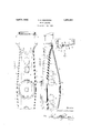
- Figure 1 is a fragmentary plan of a cast truck bolster embodying my invention.
- Figure 2 is a fragmentary side elevation of the bolster illustrated in Figure 1.
- a bolster 1 with a top wall 2, a bottom wall 3, and side walls 4. Said top and bottom walls preferably slope and converge toward one another at the ends of said bolster where guide lugs 5 and 6 are provided for cooperation with the bolster guide columns of associated frames.
- I have illustrated a bolster of the same general type as that shown in the Richards Patent No. 1,055,656, it is to be understood that I do not wish to be limited to this showing as my invention may be embodied in other hollow cast metal beams or cast metal members with normally sloping walls, such as the side walls 4 of the present bolster.
- the side walls l immediately beneath the top wall 2 are preferably vertical for a short distance, as indicated at 7 when they are sharply turned inward, as indicated at 8, to form channel sections 9.
- the side walls 4 preferably slope, as indicated at 10, inwardly, from the channel sections 9 to the edges of the bottom wall 3.
- the sloping portions 10 of the side walls are preferably apertured as indicated at 11, said apertures being most de sirably cored and the edges of the sides around said apertures being reinforced by bosses or beading 12.
- said heading has been formed on the inner surfaces of said sloping walls, as shown in the Richards Patent No. 1,055,656 referred to.
- Such construction necessitated the use of a supplemental core or loose piece in the core box to make the bead completely annular or circular as there illustrated.
- top half 13 of the bead only in the core box and the bottom half 14 in the drag pattern with the normal amount of draft being provided so that the mold and core can be formed without difficulty, as well as without the necessity of a loose piece or supplemental core.
- the top portions 13 of the beading or bosses are formed of maximum size adjacent the tops of the apertures 11 and are gradually tapered to merge into the corresponding surface of the side wall adjacent the centers of the apertures.
- the lower portions 14 of the beading 12 are formed of minimum size adjacent the lower portions of the apertures 11 and are tapered upwardly to gradually merge into the corresponding sides of the walls 4 adjacent the horizontal center lines of the apertures 11 so that the portions 14; of the beading terminate approximately opposite where the portions 13 terminate, said portions 13 and 14 together thereby being an effective substitute for a continuous bead or boss around each aperture on one side of the wall as in the Richards patent referred to.
- this manner of reinforcing the edges of the walls around the apertures is applicable to any cast devices having sloping walls, or oppositely disposed walls angularly positioned with respect to one another, providing the angle therebetween is great enough to allow tapering beading, as illustrated, while at the same i time permitting sufiicient draft to the outer surfaces of said beading for allowing proper molding.
- the bolster of the present embodiment is provided with side bearing bosses 15, which preferably taper from the outer ends 16 to the inner ends 17 to substantially merge into the upper surface of the top wall 2, the amount of taper preferably corresponding with the amount of slope of the top wall, but being opposite to said slope so as to neutralize it and give side bearing bosses with normally horizontal top surfaces.
- vertical webs 18 are provided, one or more of which are preferably disposed under each boss 15 and ezitend along or on opposite sides of the center line of the bolster vertically between the top and bottom walls thereof substantially within the projected areas of said bosses, as illustrated.
- a bolster with opposite angularly disposed walls formed with lightening apertures therein, and bosses around said apertures,the upper portions of said bosses being formed on the adjacent sides of the walls, and the .lower portions on the other sides of said walls.
- a hollow cast metal bolster comprising top, bottom and side walls, said top wall sloping downwardly toward its ends and being formed with bosses for the side bearings tapering from the top wall so that the top surfaces are substantially horizontal and auxiliary means for supporting said bosses comprising a pair of laterally spaced intermediate webs under each boss extending longitudinally of the bolster from the bosses to the bottom wall between said side walls and substantially within the vertically projected areas of said bosses.
- a hollow cast metal bolster formed with top and bottom walls sloping toward the ends thereof, side walls connecting said top and bottom walls, bosses on said top wall for side bearings, said bosses tapering so that the upper surfaces thereof are normally horizontal and a pair of laterally spaced intermediate webs connecting the top and bottom walls beneath each boss, and included between the transverse planes defining the ends of said boss.
- a beam with sloping apertured side walls and heading reinforcing the edges around said apertures the upper half of said beading being on the inside surfaces of said walls and tapering downwardly to merge into said surfaces, and the lower half of said heading being on the outer surfaces of said walls and tapering upwardly to merge into sald g surfaces.
- the method of manufacturing hollow 5 cast metal bolsters with sloping side walls apertured for decreasing the weight comprising forming reinforcing heading on the top half of the apertures on the upper surfaces of the walls, and on the bottom half on the 50 lower surfaces, and taperin the beading portions to merge into the ad acent sides of the walls with the normal amount of draft.
- the method of manufacturing hollow cast metal bolsters with downwardly and in- 55 wardly sloping side walls provided with beaded apertures therein for decreasing the weight comprising forming the upper portions of the heading on the inner surfaces of said walls, and the lower portions on the outer surfaces thereof, and tapering said portions toward one another to gradually merge tlmm into the sides of the walls with normal draft.
Landscapes
- Engineering & Computer Science (AREA)
- Mechanical Engineering (AREA)
- Moulds, Cores, Or Mandrels (AREA)
Description
April 5, 1932. D. s. BARROWS TRUCK BOLS/TER Filed Nov. 23, 1928 Patented Apr. 5, 1932 UNITED STATES PATENT OFFICE DONALD S. BARROWS, OF ROCHESTER, NEW YORK, ASSIGNOR TO THE GOULD COUPLER COMPANY, OF NEW YORK, N. Y., A CORPORATION OF MARYLAND TRUCK nonsrnn Application filed November 23, 1928.
This invention relates to beams such as railway truck bolsters or other structural devices with cored apertures in sloping or angularly disposed opposite walls thereof, and the method of casting such structures.
The principal object of my invention, generally considered, is to so form cast members with sloping walls with beaded apertures therein, that the heading around said apertures may be cast without diiiiculty, as well as to provide bolsters with side bearing bosses and reinforcements therein.
Another object of my invention is to facilitate the method. of forming bosses around cored openings in sloping or angularly disposed opposite walls of cast members so that the use of a loose piece or auxiliary core in the core box is avoided.
A further object of my invention is to facilitate the manufacture of hollow cast bolsters or other members with apertured sloping walls reinforced by beading therearound, by forming the upper portions of said head ing on the uppermost side of the sloping wall, and the lowermost portions of said heading on the lowermost side of said sloping wall, so that the top half may be formed in the core box and the bottom half in the drag pattern, thereby avoiding the necessity of a loose piece in the core box.
A still further object of my invention is to provide a hollow cast truck bolster, a beam with sloping or angularlv disposed opposite walls or other member with a normally sloping wall, and one or more cored apertures therein with bosses or heading around said apertures, the upper portion of which is formed on one side of said wall or that side uppermost with respect to the other. and the lower portion being formed on the other side, said portions tapering to gradually merge into the corresponding surfaces of the wall adjacent the centers of said apertures.
Other objects and advantages of the invention relating to the particular arrangement and construction of the various parts will become apparent as the description proceeds.
Referring to the drawings illustrating my Serial No. 321,471.
invention, the scope whereof is defined by the appended claims.
Figure 1 is a fragmentary plan of a cast truck bolster embodying my invention.
Figure 2 is a fragmentary side elevation of the bolster illustrated in Figure 1.
Figure 3 is a fragmentary transverse sec tional view on the line 3-3 of Figure 2, looking in the direction of the arrows.
Referring to the drawings in detail, like parts being designated by like reference characters, there is shown a bolster 1 with a top wall 2, a bottom wall 3, and side walls 4. Said top and bottom walls preferably slope and converge toward one another at the ends of said bolster where guide lugs 5 and 6 are provided for cooperation with the bolster guide columns of associated frames. Although I have illustrated a bolster of the same general type as that shown in the Richards Patent No. 1,055,656, it is to be understood that I do not wish to be limited to this showing as my invention may be embodied in other hollow cast metal beams or cast metal members with normally sloping walls, such as the side walls 4 of the present bolster.
In the present embodiment, the side walls l immediately beneath the top wall 2 are preferably vertical for a short distance, as indicated at 7 when they are sharply turned inward, as indicated at 8, to form channel sections 9. From the lower edges of the channel sections to the bottom wall 3, the side walls 4 preferably slope, as indicated at 10, inwardly, from the channel sections 9 to the edges of the bottom wall 3. For decreasing the weight of the bolster 1, the sloping portions 10 of the side walls are preferably apertured as indicated at 11, said apertures being most de sirably cored and the edges of the sides around said apertures being reinforced by bosses or beading 12. Heretofore said heading has been formed on the inner surfaces of said sloping walls, as shown in the Richards Patent No. 1,055,656 referred to. Such construction necessitated the use of a supplemental core or loose piece in the core box to make the bead completely annular or circular as there illustrated.
In accordance with my invention, I avoid the necessity of such a loose piece in the core box by forming the top half 13 of the bead only in the core box, and the bottom half 14 in the drag pattern with the normal amount of draft being provided so that the mold and core can be formed without difficulty, as well as without the necessity of a loose piece or supplemental core. In order to make this possible, the top portions 13 of the beading or bosses are formed of maximum size adjacent the tops of the apertures 11 and are gradually tapered to merge into the corresponding surface of the side wall adjacent the centers of the apertures. In the same way, the lower portions 14 of the beading 12 are formed of minimum size adjacent the lower portions of the apertures 11 and are tapered upwardly to gradually merge into the corresponding sides of the walls 4 adjacent the horizontal center lines of the apertures 11 so that the portions 14; of the beading terminate approximately opposite where the portions 13 terminate, said portions 13 and 14 together thereby being an effective substitute for a continuous bead or boss around each aperture on one side of the wall as in the Richards patent referred to. It will also be obvious that this manner of reinforcing the edges of the walls around the apertures is applicable to any cast devices having sloping walls, or oppositely disposed walls angularly positioned with respect to one another, providing the angle therebetween is great enough to allow tapering beading, as illustrated, while at the same i time permitting sufiicient draft to the outer surfaces of said beading for allowing proper molding.
The bolster of the present embodiment is provided with side bearing bosses 15, which preferably taper from the outer ends 16 to the inner ends 17 to substantially merge into the upper surface of the top wall 2, the amount of taper preferably corresponding with the amount of slope of the top wall, but being opposite to said slope so as to neutralize it and give side bearing bosses with normally horizontal top surfaces. In order to provide for the adequate support and reinforcement of the top wall and side bearing bosses 15 vertical webs 18 are provided, one or more of which are preferably disposed under each boss 15 and ezitend along or on opposite sides of the center line of the bolster vertically between the top and bottom walls thereof substantially within the projected areas of said bosses, as illustrated.
From the foregoing disclosure it will be seen that I have devised a form of hollow cast bolster with lightening apertures in the side walls thereof, the edges of said side walls around said apertures being reinforced by bosses which are more readily formed by be ing disposed half on one side and half on the other side of the corresponding wall. It will be obvious that this feature of my invention is applicable to any cast sloping wall with a cored opening therein. In the present em bodiment, I have also shown a special form of side bearing boss with a reinforcement therefor extending between the top and bottom walls of the bolster.
Having now described my invention, I claim:
1. A bolster with a sloping side wall formed with a lightening aperture therein, and a boss around said aperture, the upper portion of said boss being formed on one side and the lower portion on the other side of said wall. 5.
2. A bolster with opposite angularly disposed walls formed with lightening apertures therein, and bosses around said apertures,the upper portions of said bosses being formed on the adjacent sides of the walls, and the .lower portions on the other sides of said walls. I I
.3. A hollow cast metal'bolster with a'relativcly wide top wall, a relatively narrow bot tom wall and side walls extending downwardly from said top wall and converging to meet the sideedges of the bottom wall, said converging portions being apertured for decreasing the weight of the bolster, the edges of the walls around said apertures being reinforced by beading, the upper portions of the beading being on the inside surfaces of the walls and tapering downward to merge into said walls, and the lower portions of said beading being on the outer surfaces of said walls and tapering upward to merge into said walls.
4. A hollow cast metal bolster comprising top, bottom and side walls, said top wall sloping downwardly toward its ends and being formed with bosses for the side bearings tapering from the top wall so that the top surfaces are substantially horizontal and auxiliary means for supporting said bosses comprising a pair of laterally spaced intermediate webs under each boss extending longitudinally of the bolster from the bosses to the bottom wall between said side walls and substantially within the vertically projected areas of said bosses.
5. A hollow cast metal bolster formed with top and bottom walls sloping toward the ends thereof, side walls connecting said top and bottom walls, bosses on said top wall for side bearings, said bosses tapering so that the upper surfaces thereof are normally horizontal and a pair of laterally spaced intermediate webs connecting the top and bottom walls beneath each boss, and included between the transverse planes defining the ends of said boss.
6."A beam with a sloping side wall, an aperture therein, and reinforcing beading around said aperture, said beading around the lower side of the aperture being formed on the lowermost surface of the wall, and the beading around the upper side of the aperture being formed on the uppermost surface of said wall.
7'. A hollow beam with opposite angularly disposed walls, apertures therein, and reinforcing beading around said apertures, said heading being formed on the outside surfaces of the walls around those portions of the apertured walls nearest together and on the inside surfaces of said walls around the apertured portions farthest apart.
8. A beam with sloping apertured side walls and heading reinforcing the edges around said apertures, the upper half of said beading being on the inside surfaces of said walls and tapering downwardly to merge into said surfaces, and the lower half of said heading being on the outer surfaces of said walls and tapering upwardly to merge into sald g surfaces.
9. A beam with a wall having a cored opening therethrough and a boss encircling said opening, one-half of said boss being disposed on one side of said wall and the other half 1.3 on the other side thereof.
10. A beam with a sloping wall and a cored opening therethrough, a boss surrounding said opening, one-half of said boss being on the uppermost side of the opening and the ill) uppermost surfaces of said wall, the other half being on the lowermost side and lower most surface of said wall.
11. A beam with a wall having a cored opening therethrough, said wall sloping and 35 being provided with a boss surrounding said opening for reinforcing purposes, a portion of said boss being disposed on the uppermost side of said opening on the uppermost surface of said wall and the remainder there an of being disposed on the lowermost side of said opening and the lowermost surface of said wall, the adjacent portions of said bosses tapering to gradually merge into the wall.
12. The method of manufacturing hollow 5 cast metal bolsters with sloping side walls apertured for decreasing the weight, comprising forming reinforcing heading on the top half of the apertures on the upper surfaces of the walls, and on the bottom half on the 50 lower surfaces, and taperin the beading portions to merge into the ad acent sides of the walls with the normal amount of draft.
The method of manufacturing hollow cast metal bolsters with downwardly and in- 55 wardly sloping side walls provided with beaded apertures therein for decreasing the weight. comprising forming the upper portions of the heading on the inner surfaces of said walls, and the lower portions on the outer surfaces thereof, and tapering said portions toward one another to gradually merge tlmm into the sides of the walls with normal draft.
In testimony whereof I affix my signature.
DONALD S. BARROWVS.
Priority Applications (1)
| Application Number | Priority Date | Filing Date | Title |
|---|---|---|---|
| US321471A US1852393A (en) | 1928-11-23 | 1928-11-23 | Truck bolster |
Applications Claiming Priority (1)
| Application Number | Priority Date | Filing Date | Title |
|---|---|---|---|
| US321471A US1852393A (en) | 1928-11-23 | 1928-11-23 | Truck bolster |
Publications (1)
| Publication Number | Publication Date |
|---|---|
| US1852393A true US1852393A (en) | 1932-04-05 |
Family
ID=23250726
Family Applications (1)
| Application Number | Title | Priority Date | Filing Date |
|---|---|---|---|
| US321471A Expired - Lifetime US1852393A (en) | 1928-11-23 | 1928-11-23 | Truck bolster |
Country Status (1)
| Country | Link |
|---|---|
| US (1) | US1852393A (en) |
Cited By (2)
| Publication number | Priority date | Publication date | Assignee | Title |
|---|---|---|---|---|
| US20060285971A1 (en) * | 2005-06-15 | 2006-12-21 | Matheny Alfred P | Shroud tip clearance control ring |
| US7681506B2 (en) | 2005-06-16 | 2010-03-23 | National Steel Car Limited | Truck bolster |
-
1928
- 1928-11-23 US US321471A patent/US1852393A/en not_active Expired - Lifetime
Cited By (2)
| Publication number | Priority date | Publication date | Assignee | Title |
|---|---|---|---|---|
| US20060285971A1 (en) * | 2005-06-15 | 2006-12-21 | Matheny Alfred P | Shroud tip clearance control ring |
| US7681506B2 (en) | 2005-06-16 | 2010-03-23 | National Steel Car Limited | Truck bolster |
Similar Documents
| Publication | Publication Date | Title |
|---|---|---|
| US2012949A (en) | Truck side frame | |
| US1852393A (en) | Truck bolster | |
| US1990095A (en) | Truck side frame for railway cars | |
| US1969131A (en) | Truck bolster | |
| US1748749A (en) | Side frame | |
| US1957570A (en) | Truck bolster | |
| US2097579A (en) | Truck side frame | |
| US1985469A (en) | Railway car truck bolster | |
| US2220218A (en) | Spring plankless truck | |
| US2322599A (en) | Truck side frame | |
| US1710624A (en) | Side frame | |
| US1660968A (en) | Side frame | |
| US2348694A (en) | Bolster | |
| US1736251A (en) | Side frame | |
| US1785871A (en) | Side frame for car trucks | |
| US2139434A (en) | Railway truck | |
| US1673754A (en) | Side frame | |
| US1531639A (en) | Car-truck side frame | |
| US1893475A (en) | Truck side frame | |
| US1718470A (en) | Cast-steel side frame | |
| US1531640A (en) | Journal box | |
| US2226678A (en) | Welded truck bolster | |
| US1694577A (en) | Side frame | |
| US1745673A (en) | Truck side frame | |
| US1748238A (en) | Cast-steel side frame |