US1852390A - Locking mechanism for switch stands - Google Patents
Locking mechanism for switch stands Download PDFInfo
- Publication number
- US1852390A US1852390A US34766529A US1852390A US 1852390 A US1852390 A US 1852390A US 34766529 A US34766529 A US 34766529A US 1852390 A US1852390 A US 1852390A
- Authority
- US
- United States
- Prior art keywords
- lever
- cover
- switch
- plate
- latching
- Prior art date
- Legal status (The legal status is an assumption and is not a legal conclusion. Google has not performed a legal analysis and makes no representation as to the accuracy of the status listed.)
- Expired - Lifetime
Links
- 230000007246 mechanism Effects 0.000 title description 40
- 238000010276 construction Methods 0.000 description 6
- 241001669679 Eleotris Species 0.000 description 5
- 230000001419 dependent effect Effects 0.000 description 3
- 210000005069 ears Anatomy 0.000 description 3
- 230000005484 gravity Effects 0.000 description 3
- 239000000725 suspension Substances 0.000 description 2
- 230000000994 depressogenic effect Effects 0.000 description 1
- 230000002542 deteriorative effect Effects 0.000 description 1
- 239000002184 metal Substances 0.000 description 1
- QVRVXSZKCXFBTE-UHFFFAOYSA-N n-[4-(6,7-dimethoxy-3,4-dihydro-1h-isoquinolin-2-yl)butyl]-2-(2-fluoroethoxy)-5-methylbenzamide Chemical compound C1C=2C=C(OC)C(OC)=CC=2CCN1CCCCNC(=O)C1=CC(C)=CC=C1OCCF QVRVXSZKCXFBTE-UHFFFAOYSA-N 0.000 description 1
- 230000001681 protective effect Effects 0.000 description 1
- 230000000717 retained effect Effects 0.000 description 1
- XLYOFNOQVPJJNP-UHFFFAOYSA-N water Substances O XLYOFNOQVPJJNP-UHFFFAOYSA-N 0.000 description 1
Images


Classifications
-
- B—PERFORMING OPERATIONS; TRANSPORTING
- B61—RAILWAYS
- B61L—GUIDING RAILWAY TRAFFIC; ENSURING THE SAFETY OF RAILWAY TRAFFIC
- B61L5/00—Local operating mechanisms for points or track-mounted scotch-blocks; Visible or audible signals; Local operating mechanisms for visible or audible signals
- B61L5/10—Locking mechanisms for points; Means for indicating the setting of points
-
- Y—GENERAL TAGGING OF NEW TECHNOLOGICAL DEVELOPMENTS; GENERAL TAGGING OF CROSS-SECTIONAL TECHNOLOGIES SPANNING OVER SEVERAL SECTIONS OF THE IPC; TECHNICAL SUBJECTS COVERED BY FORMER USPC CROSS-REFERENCE ART COLLECTIONS [XRACs] AND DIGESTS
- Y10—TECHNICAL SUBJECTS COVERED BY FORMER USPC
- Y10T—TECHNICAL SUBJECTS COVERED BY FORMER US CLASSIFICATION
- Y10T70/00—Locks
- Y10T70/50—Special application
- Y10T70/5611—For control and machine elements
- Y10T70/569—Lever
- Y10T70/5695—Guide
- Y10T70/5708—Fixed lever-receiving keeper
Definitions
- This invention relates to railway switch
- the present invention is directed particularly to association with a typeof switch actuating mechanism referred to as the ground throw stand, although in certain of its aspects the invention may be applicable to other types of switch actuating mechanism. It is one of the objects of the invention to provide a locking mechanism which may be applied quickly, inexnensively and conveniently to a standard type of ground throw stand, of which many thousands are in operation at the present time.
- Another object of the invention is to equip a switch stand with a type of locking devlce that is generally taken in a more serious manner by the railroad operatives than the ordinary padlocks now extensively used, and to do this by a means providing against all recognized conditions of carelessness or inten tional or unintentional misuse.
- a further object of the invention is to incase the standard latching mechanism of a switch operating lever and normally protect this latching mechanism from the elements and from possible operation by unauthorized persons.
- the present invention provides against many contingencies in a manner that will be in part obvious and in part particularly stated in the following description.
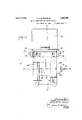
- Figure 1 is a plan view of a standard type of ground throw switch stand with the improved locking device arranged in operative position.
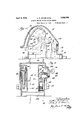
- Figure 2 is a view in end elevation of the locking device with the cover shown lifted so as to permit the release of the switch actuating lever.
- Figure 3 is a view in front elevation of the device shown in Figure 2.
- the standard latching mechanism for the switch actuating lever is shown in dot and dash lines.
- Figure 4 is a plan view of the device shown in Figures 2 and 3. In this view, the stand ard latching device for the switch actuating lever and the actuating lever itself are shown in dot and dash lines.
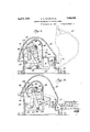
- Figure 5 is a View in cross section taken substantially along the line 55 of Figure 4, the cover of the locking device being shown, however, in its closed position.
- Figure 6 is a view in cross section taken substantially along the line 6-6 of Figure 4, the cover being shown, however, in its closed position.
- Figure 7 is a view in cross sectiontaken substantially along the line 7-7 of Figure 6 looking in the direction of the arrows.
- Figure 8 is a view in cross section taken in the same plane and looking in the same direetion as in Figure 7, but with the parts in the positions that. they may assume when the cover has been lifted and the switch actuating lever operated to its opposite position.
- Figure 9 is a. view in cross section taken substantially along the line 9--9 of Figure 6 looking in the directions of the arrows.
- Figure 10 is a similar sectional view showing the action of the parts illustrated in F igure 9 which permits lifting of the cover when the switch operating lever is out of the posi tion intended for it when looking is desired.
- FIG. 1 of the drawings a standard form of ground throw switch stand is shown diagrammatically in Figure 1 of the drawings.
- the switch stand is provided with a base 20 which spreads over adjacent railroad ties or sleepers, and is spiked thereto as indicated at 21.
- the stand has the usual target spindle 22, a casing'23 provided with a boss 24, in which is journalled the switch operating lever 25 weighted as indicated at 26 at its outer end.
- the switch lever is adapted to be thrown from the latched position shown in Figure 1 through an arc of one hundred and eighty degrees substantially, to a latched position over an adjacent sleeper.
- the target is give a rotative movement, and crank-arm 27 is rotated to transmit a longitudinal movement to a tie rod 28, which in turn connects with the switch rail that is to be manipulated.
- All this construction isof a standard and well known type in very extensive use on many railroads today.
- the position of the parts as shown in Figurel of the drawings represents what is called the main line or closed position; that is, one in which the switch is set for through passage of a train along the track mainly. used.
- the switch lever is thrown one hundred and eighty degrees from the position shown in Figure 1, the switch parts are set for shunting the train to a branch line, siding or cross-over. It is a railroad rule that the switch stand mechanism shall be normally retained in the main line or closed position.
- Latching devices for the switch lever are secured respectively to the adjacent sleepers 1 and are adapted to automatically set themselves in position to maintain the switch lever down close to the sleeper. They are adapted opposite position.
- latching mechanism is indicated by the dot and dash lines of Figures 3, 4 and 5, and comprises a plate 30, firmly secured to the sleeper, having a pair of spaced upright brackets 31 and 32, between which a latching dog 33 is loosely pivotally supported at 34.
- a member 35 having a foot treadle 36, and an actuating finger 37 is also pivoted between the brackets 31 and 32 as indicated at 38.
- the latching dog 33 has a forwardly and downwardly extending arm 39 terminating in outwardly extending lugs 40 and 41, which are provided for the purpose of serving as a finger grip.
- a stop pin 42 projects outwardly a short distance from either side of the latching dog, and in the movement of the dog to unlatching position eventually contacts with a recessed portion 43 of the upstanding brackets 31 and 32.
- the operation of the latching device is as follows : The operator steps von the foot treadle 36, which in its pivotal movement swings the finger 37 carrying with it the latching dog 33 by reason of engagement of the finger with the downwardly and. out.- wardly extending arm 39 of the latching dog.
- the dog 33 swings about the pivot 34 until the pins 42 contact with the stop faces 43 of the brackets31 and 32. This action may be effected by lifting the arm 39 by the finger grip comprising the lugs 40 and 41.
- the parts may return to the normal latching position ( Figure 5) by reason of the weight of the outwardly extending bosses 40 and the outwardly and downwardly extending arm 39 overbalancing the nose on the opposite side of the pivot point 34.
- the nose 50 is provided with an upper cam face 51 and a lower cam face 52, the upper cam face being for the purpose of allowing the switch lever to operate the latching device when returning fromthe shunt line position to the main line position. 'As soon, however, as the switch lever has passed the high point 53 at the junction of the upper and lower cam faces, the weight of the parts, as heretofore described, causes the nose. of the latching dog to immediately assume the position shown in Figure 5, which is the normal, lever-latching position or the mechanism.
- This latching device is also standard equipment on the railroads, and has been previously secured against.
- a frame or housing is secured in position on the railroad sleeper around and incasing one of the latching mechanisms just previously described.
- the housing has abase 61 and upstanding hollow brackets or arms 62 and 63.
- the arm 62 is provided with a barrel 64, which contains a simple key-operative mechanism controlling the action of a crank 65.
- the barrel is provided with a face plate 66, which has fixed thereto a spring pressed shield or guard 67 This shield or guard normally positions itself opposite a keyhole 68 in the barrel, and protects same from the introduction of snow, iceand foreign matter.
- the shield is provided with a contacting edge 69 shaped to conform to the side of the key 70, thereby locating the key without the necessity of visualizing the key hole.
- the crank operates in a segmentally shaped aperture 71 in a plate 72 (see Figures 6, 9 and 10).
- the housing 60 is also provided with a hinged locking cover 75, preferably in the shape of a canopy, and having ears 76 at either side forming a yoke straddling the frame near the base 61.
- the cover is secured to the frame by threaded bolts 77 passing through holes in the ears 76 and threading into bosses 78 cast on the inside of a thin, upstanding wall 7 9 cast integral with the base 01. These bolts are secured against withdrawal under ordinary conditions by inserting cotter pins 80 through holes provided therefor in the bosses 78 and through corresponding holes in the shanks of the bolts.
- the ears are slightly spaced from the upstanding walls 79 so as to provide for free swinging movement of the cover or canopy.
- the cover is provided on its inner face with a locking lug 90 which cooperates in the action of locking the cover in closed position with a detent or nose 91 projecting from the plate 72 (see Figure 9).
- This plate has 21 peculiar floating suspension in the hollow bracket 62. It is pivotally connected at 100 to a pair of links 101 on opposite sides of the plate 72, the other ends of these links being pivotally connected at 102 on opposite sides of a lever arm 103, one end of which arm is pivotally connected to the bracket 62 by a pin 10a.
- the links 101 are also supported by a pair of spaced links 105 pivotally connected to the bracket 62 at 100 and pivotally connected at their other ends at 107 to the links 101 by a pin 108.
- the links 105 are spaced apart by a spacing sleeve 109 and straddle the spaced links 101, which in turn straddle the plate 72.
- the lever arm 103 is permitted to move freely between the spaced links 105.
- the pin 108 passes through both sets of links and through the plate 72 in an arcuate slot 110.
- the detent plate 72 is permitted a substantial range of pivotal movement about the pivot point 100 under the rotary action of the crank 65, which is in turn moved by the key 70.
- the plate 72 is provided with a weighted portion 120 having a shoulder 121 adapted to contact with one edge of link 105 and limit the pivotal movement of the plate '72 in one direction under the influence of gravity.
- Movement of the key causes the crank 65 to move the crank pin along an edge 122 of the aperture 71 to lift the weighted portion of the detent plate around the pivot point 100, withdrawing the main by reason of its weight being substantially disposed on the opposite side of the hinge. This removes the cover from the nor mal path of the switch lever 25, but the latter is still held by the latching device involving the latching dog 50.
- this latching dog Upon operation of the foot treadle 36 or the finger grip lugs 4:0 and 41 this latching dog is then withdrawn from the normal path of the operating lever, leaving the same free tobe thrown to its opposite latch position through an angle of one hundred and eighty degrees.
- the key is operated to unlock the cover by moving the detent plate 7 2 around the pivot 100, the arcuate slot 110 moves along the pin 108, so that in the normal key actuation of the detent plate 72 there is no intentional disturbance of the links and levers 101, 105 and 103.
- This link and lever mechanism is provided for the main purpose of preventing the cover from becoming locked at any time before the switch lever has been returned to its latched position beneath the cover, that is, in the main line or closed position of the switch.
- the finger 142 is restrained by the switch lever 25 against sufiicient upward movement to permit the lateral movement of the detent plate just previously described, and the cover is therefore held in its closed and locked condition.
- the effective locking of the cover is dependent, therefore, upon the switch lever being properly positioned for main line operation.
- a return of the cover to closure position automatically sets the looking mechanism.
- the detent plate 2 is caused to pivot around the pin 100 by the engagement of a cam face 143 of the lug 90 on the cover with a cam face 1 14 on the nose 91 of the detent plate. This movement is permitted by the pin and slot connection 108-110.
- bracket 62 of the liar contour has an inwardly extending short flange 152. which in normal locking position bears against one of the lugs of the finger grip on the end of the arm 39 of the latching dog 33, (see Figure 5).
- This flange 152 when in position with the cover 75 closed, prevents the upward movement of.
- Another plate 155 is pivotally mounted for movement in the bracket 63 on a pin156.
- This plate is heavily overbalanced by excess of weight on its forward side 157, and is provided with a nose 158 at the rear of the pivot 156. It is also formed with an offset lug 159, having a cam edge 160 adapted to cam along the edge surface 161 of the plate 150 and urge the latter into the raised position shown clearly in Figure 8 of the drawings.
- the pivotal movement of the plate155 under the influence of gravity is brought to a stop by a shoulder 162 engaging a portion 16.3 of the bracket 63.
- the nose 2 158 of the plate 155 moves in a slot 164 provided in the rear face of the hollow bracket 63.
- the movement of the plate 155 in the opposite direction is limited by a lug 170 on the'plate abuting a shoulder 171 formed on the inside of the bracket arm 63.
- the short flange 152 of the plate 150 prevents the latching mechanism being operated when the cover is closed. lVhen the cover is unlocked and thrown to its open position, the foot treadle 36 or the finger grip 40t1 may be operated to release the latching mechanism.
- the boss 40 on the end of arm 39 of the latching mechanism raises and carries with it the plate 150, the
- the switch lever is holding the overbalanced plate 155 against movement by reason of the engagement of the side of the switch lever with the point of the nose 158.
- the switch lever is, however, free to be moved, and upon movement the plate 155 pivots by gravity around the pin 156, the cam lug 159 further raises the plate 150, and the lug 159 positions itself in dead center 1 alignment between the pivot point 156 and the returned to its normal position.
- the stop plate 150 quires for effectivelocking action that the switch lever be in latched position over the finger 142 of lever 103. If the switch lever is not in that position, the lever 103 may pivot upwardly allowing the lateral movement of the detent plate 7 2, as is shown in Figure 10 of the drawings and as previously described herein.
- the plate 150 in cooperation with the plate 155 serves asa means for preventing the closing of the cover during such time as the switch lever is out of the main line position.
- the unbalanced plate 155 (see Figures 7 and 8) is permitted to rotate until the shoulder 162 brings up against the stop 163 of the frame. This further lifts the plate 150 due to the camming action of the surface 160 of lug 159, and positions the lug 159 substantially in dead center alignment with the pivot 156 and the plate 150. With the parts as now positioned, the plate 150 is disposed in the normal path of travel of the lug 180 on the inside of the cover 7 5 so that the cover is prevented from returning to fully closed position by engagement of the lug with the late.
- the operator throws the switch lever back to its original position.
- the lever is forced past the nose 33 of the latching mechanism and caused to overcome the unbalanced weight of plate 155 by the application of pressure on the inclined face 181 of the nose 158 of said plate.
- the latching nose assumes its original position opposing reverse movement of the switch lever, and the plate 150 drops substantially into the position shown in Figure 7 of the drawings, permitting the cover to be closed.
- the parts are as indicated by the full lines in Figure 9 of the drawings, the detent plate 72 having pivotally yielded around the pin 100 due to the action of cam face 143 of the cover stop 90 upon the cam face 144 of the detent nose 91.
- the detent plate swings back again into the position shown in Figure 9, and prevents opening of the cover except, as previously described, by the operation of the crank under control of the key 70.
- the key-operative mech anism fails in operation, as by breaking a key in the lock, it is, of course, necessary to gain access to the latch for the purpose of operating the switch lever. This is provided for by the attachment of the swinging cover or canopy 7 5 to the frame by bolts 77, lugs 78 and cotter pins 80. In order to remove the cover, it is only necessary to apply sufficient rotative force to the bolts to shear the soft metal cotter pins, whereupon the bolts may be withdrawn and the cover removed from the frame.
- a protective housing is provided for the latching mechanisms which have heretofore been entirely exposed.
- a built-in lock is substituted for the ordinary padlock previously used which, while involving higher first cost, is essentially more durable and longer-lived than the padlock.
- a sturdy locking device is provided for the housing, and the construction and operation of the cover and locking mechanism are such that the operator is impelled to return the switch to main line or closed position upon each actuation; otherwise he must leave the cover entirely open and the plate 150 projecting upwardly.
- a latching device for said lever comprising a yielding dog and means for manually moving the dog to release the lever, and a frame fitted around the latching device and relatively fixed therewith, said frame comprising a movable cover and having provision for locking the cover closed over the latching device and lever.
- movable switch operating lever a latching device therefor, and a casing fitted around said latching device comprising a hinged cover movable to closure position over the latching device and the lever when latched thereby, and means arranged in said casing preventing opening of the cover or unlatching of the latch when the cover is closed.
- a movable switch operating lever a latching device therefor. and a casing fitted around said latching device comprising a hinged cover movable to closure position over the latching device and the lever when latched thereby, means arranged in said casing preventing opening of the cover or unlatching of the latch when the cover is closed, said means being dependent in their effective action upon a position of the lever under control of the latching device.
- a movable switch-operating lever comprising a movable locking cover, key-operative means to unlock the cover, automatic means adapt ed to lock said cover upon closure, and means adapted to prevent closure of the cover until the said lever has been moved to latching position.
- a locking mechanism for a switch-operating lever having in combination, a housing with a hinged cover movable into and out of position over the lever, a movable locking dog pivotally supported on said housing, a key-controlled member for moving the dog to cover-unlocking position, and a member movable by the lever when operated to oppose closure of the cover, said movable member being returned to, unopposing position when the lever is returned to normal position with in the housing.
- a latching device for said lever comprising a yielding dog which yields as the lever passes in one direction and resists movement of the lever in the opposite direction, manually operable means for moving the dog out of the path of the lever, and a locking mechanism comprising a casing with hinged locking cover. having key controlled means for unlocking the cover.
- a pivoted lever for operation of the connections to the switch rail
- a latching device for said lever comprising a yielding dog which yields as the lever passes in one direction and resists movement of the lever in the opposite direction, manually operable means'for moving the dog out of the path of the lever
- a locking mechanism comprising a casing with hinged locking cover, having key controlled means for unlocking'the cover, and having provision forpreventing throw of the lever when the cover is closed over the latching device and the lever.
- a switching device for railroads a movable switch-operating lever, a latching device therefor, and a locking mechanism around said latching device dependent for its looking on the'presence ofthe'saidlever in position in the latching device.
- a locking mechanism for a switch-operating lever having in combination, a housing comprising a locking cover movable overthe lever, means for locking said cover closed, key-operative means for unlocking the cover so as to operate the lever, and means normally preventing closure of the cover until return of the lever to normal position.
- a locking mechanism for a switch-op crating lever having in combination, a housing comprising a locking cover movable over the lever, means for locking said cover closed,
Landscapes
- Engineering & Computer Science (AREA)
- Mechanical Engineering (AREA)
- Switch Cases, Indication, And Locking (AREA)
Description
April 5, 1932.
A. A. ADAMS ET AL LOCKING MECHANISM FOR SWITCH STANDS Filed March 16, 1929 6 Sheets-Sheet. 1
April 1932. A. A. ADAMS ET AL 1,852,390
LOCKING MECHANISM FOR SWITCH STANDS Filed March 16, 1929 6 Sheets-Sheet 2 M7160 7' M5, W
A ril 5, 1932. A. A. ADAMSET AL 1,352,390
LOCKING MECHANISM FOR SWITCH STANDS Filed March 16. 1929 e Sheets-Sheet. z
April 5, 1932. A. A. ADAMS ET AL 1,852,390 A LOOKING MECHANISM FOR SWITCH STANDS Filed March 16. 1929 '6 Sheets-Sheet. 4
l I Q Y M9 Wvewvar 7 g WJi M April 5, 1932. A. A. ADAMS ET AL 1,852,390
LOCKING MECHANISM FOR SWITCH STANDS Filed March 16. 1929 5 Sheets-Sheet. 5
A ril 5, 1932. A. A. ADAMS ETAL LOCKING MECHANISM FOR SWITCH STANDS Filed March 16, 1929 6 Sheets-Sheet 6 Patented Apr. 5, 1932 UNITED STATES PATENT OFFICE ARTHUR A. ADAMS AND ROBERT G. MORSE, OF BROOKLINE, MASSACHUSETTS, AS-
SIGNORS TO RAILWAY SAFETY SWITCH LOCK COMPANY, OF SEATTLE, WASHINGTON A CORPORATION OF \VASI'IINGTON LOCKING MECHANISM FOR SWITCH STANDS Application filed March 16, 1929. Serial No. 347,665.
This invention relates to railway switch,
stands and means for locking the same, and, with regard to certain more specific features thereof, to locking devices for the operating levers which in turn control the switch movement.
The present invention is directed particularly to association with a typeof switch actuating mechanism referred to as the ground throw stand, although in certain of its aspects the invention may be applicable to other types of switch actuating mechanism. It is one of the objects of the invention to provide a locking mechanism which may be applied quickly, inexnensively and conveniently to a standard type of ground throw stand, of which many thousands are in operation at the present time.
Another object of the invention is to equip a switch stand with a type of locking devlce that is generally taken in a more serious manner by the railroad operatives than the ordinary padlocks now extensively used, and to do this by a means providing against all recognized conditions of carelessness or inten tional or unintentional misuse.
A further object of the invention is to incase the standard latching mechanism of a switch operating lever and normally protect this latching mechanism from the elements and from possible operation by unauthorized persons.
The present invention provides against many contingencies in a manner that will be in part obvious and in part particularly stated in the following description.
This invention accordingly consists of the various combinations of elements, arrangements of parts and features of construction which will be more particularly pointed out in the following description and illustrated in the accompanying drawings, and the scope of the application of which will be indicated in the appended claims.
In the accompanying drawings Figure 1 is a plan view of a standard type of ground throw switch stand with the improved locking device arranged in operative position. h
Figure 2 is a view in end elevation of the locking device with the cover shown lifted so as to permit the release of the switch actuating lever.
Figure 3 is a view in front elevation of the device shown in Figure 2. In this figure, the standard latching mechanism for the switch actuating lever is shown in dot and dash lines.
Figure 4 is a plan view of the device shown in Figures 2 and 3. In this view, the stand ard latching device for the switch actuating lever and the actuating lever itself are shown in dot and dash lines.
Figure 5 is a View in cross section taken substantially along the line 55 of Figure 4, the cover of the locking device being shown, however, in its closed position.
Figure 6 is a view in cross section taken substantially along the line 6-6 of Figure 4, the cover being shown, however, in its closed position.
Figure 7 is a view in cross sectiontaken substantially along the line 7-7 of Figure 6 looking in the direction of the arrows.
Figure 8 is a view in cross section taken in the same plane and looking in the same direetion as in Figure 7, but with the parts in the positions that. they may assume when the cover has been lifted and the switch actuating lever operated to its opposite position.
Figure 9 is a. view in cross section taken substantially along the line 9--9 of Figure 6 looking in the directions of the arrows.
Figure 10 is a similar sectional view showing the action of the parts illustrated in F igure 9 which permits lifting of the cover when the switch operating lever is out of the posi tion intended for it when looking is desired.
There are certain definite and necessary requirements of a switch stand for railroads.
Obviously, it is desirable primarily from the standpoint of safety that there shall be some means for preventing unauthorized manipulation of the switch. This, previously, has been taken care of in a fashion by using an ordinary padlock sometimes with, and sometimes without, a chain by which it is attached to the switch stand. This type of locking means is not seriously regarded by the railroad operatives who neglect the locking operation, and also lose padlocks to the value of many thousands of dollars each year. The employment of a built-in lock is attended with several problems not ordinarily present with the padlock, and these problems must be solved before the built-in lock is suitable for railroad usage.
Referring now more particularly to the drawings, a standard form of ground throw switch stand is shown diagrammatically in Figure 1 of the drawings. The switch stand is provided with a base 20 which spreads over adjacent railroad ties or sleepers, and is spiked thereto as indicated at 21. The stand has the usual target spindle 22, a casing'23 provided with a boss 24, in which is journalled the switch operating lever 25 weighted as indicated at 26 at its outer end. The switch lever is adapted to be thrown from the latched position shown in Figure 1 through an arc of one hundred and eighty degrees substantially, to a latched position over an adjacent sleeper.
Through suitable connections, the target is give a rotative movement, and crank-arm 27 is rotated to transmit a longitudinal movement to a tie rod 28, which in turn connects with the switch rail that is to be manipulated. All this construction isof a standard and well known type in very extensive use on many railroads today. The position of the parts as shown in Figurel of the drawings represents what is called the main line or closed position; that is, one in which the switch is set for through passage of a train along the track mainly. used. When the switch lever is thrown one hundred and eighty degrees from the position shown in Figure 1, the switch parts are set for shunting the train to a branch line, siding or cross-over. It is a railroad rule that the switch stand mechanism shall be normally retained in the main line or closed position.
Latching devices for the switch lever are secured respectively to the adjacent sleepers 1 and are adapted to automatically set themselves in position to maintain the switch lever down close to the sleeper. They are adapted opposite position.
to be manually operated to unlatching condition to permit the throw of the lever to the One of these latching mechanisms is indicated by the dot and dash lines of Figures 3, 4 and 5, and comprises a plate 30, firmly secured to the sleeper, having a pair of spaced upright brackets 31 and 32, between which a latching dog 33 is loosely pivotally supported at 34. A member 35 having a foot treadle 36, and an actuating finger 37 is also pivoted between the brackets 31 and 32 as indicated at 38. The latching dog 33 has a forwardly and downwardly extending arm 39 terminating in outwardly extending lugs 40 and 41, which are provided for the purpose of serving as a finger grip. A stop pin 42 projects outwardly a short distance from either side of the latching dog, and in the movement of the dog to unlatching position eventually contacts with a recessed portion 43 of the upstanding brackets 31 and 32.
The operation of the latching device is as follows :The operator steps von the foot treadle 36, which in its pivotal movement swings the finger 37 carrying with it the latching dog 33 by reason of engagement of the finger with the downwardly and. out.- wardly extending arm 39 of the latching dog. The dog 33 swings about the pivot 34 until the pins 42 contact with the stop faces 43 of the brackets31 and 32. This action may be effected by lifting the arm 39 by the finger grip comprising the lugs 40 and 41. The parts may return to the normal latching position (Figure 5) by reason of the weight of the outwardly extending bosses 40 and the outwardly and downwardly extending arm 39 overbalancing the nose on the opposite side of the pivot point 34. It is to be noted that the nose 50 is provided with an upper cam face 51 and a lower cam face 52, the upper cam face being for the purpose of allowing the switch lever to operate the latching device when returning fromthe shunt line position to the main line position. 'As soon, however, as the switch lever has passed the high point 53 at the junction of the upper and lower cam faces, the weight of the parts, as heretofore described, causes the nose. of the latching dog to immediately assume the position shown in Figure 5, which is the normal, lever-latching position or the mechanism. This latching device is also standard equipment on the railroads, and has been previously secured against. unauthorized manipulation by the passing of a padlock hasp through a hole 54, which assumes a position just below the stop faces 43 of the brackets when the mechanism is in normal latching condition. It is to benoted that according to this standard construction, the latching mechanism and padlock were entirely exposed to the elements, the padlock hanging, of course, in hap-hazard position, taking up snow and water and therefore rapidly deteriorating.
Coming now to a description of the improvements in this standard construction which are provided by the present inven tion, a frame or housing is secured in position on the railroad sleeper around and incasing one of the latching mechanisms just previously described. The housing has abase 61 and upstanding hollow brackets or arms 62 and 63. The arm 62 is provided with a barrel 64, which contains a simple key-operative mechanism controlling the action of a crank 65. The barrel is provided with a face plate 66, which has fixed thereto a spring pressed shield or guard 67 This shield or guard normally positions itself opposite a keyhole 68 in the barrel, and protects same from the introduction of snow, iceand foreign matter.
The shield is provided with a contacting edge 69 shaped to conform to the side of the key 70, thereby locating the key without the necessity of visualizing the key hole. The crank operates in a segmentally shaped aperture 71 in a plate 72 (see Figures 6, 9 and 10).
The housing 60 is also provided with a hinged locking cover 75, preferably in the shape of a canopy, and having ears 76 at either side forming a yoke straddling the frame near the base 61. The cover is secured to the frame by threaded bolts 77 passing through holes in the ears 76 and threading into bosses 78 cast on the inside of a thin, upstanding wall 7 9 cast integral with the base 01. These bolts are secured against withdrawal under ordinary conditions by inserting cotter pins 80 through holes provided therefor in the bosses 78 and through corresponding holes in the shanks of the bolts. The ears are slightly spaced from the upstanding walls 79 so as to provide for free swinging movement of the cover or canopy. The cover is provided on its inner face with a locking lug 90 which cooperates in the action of locking the cover in closed position with a detent or nose 91 projecting from the plate 72 (see Figure 9). This plate has 21 peculiar floating suspension in the hollow bracket 62. It is pivotally connected at 100 to a pair of links 101 on opposite sides of the plate 72, the other ends of these links being pivotally connected at 102 on opposite sides of a lever arm 103, one end of which arm is pivotally connected to the bracket 62 by a pin 10a. The links 101 are also supported by a pair of spaced links 105 pivotally connected to the bracket 62 at 100 and pivotally connected at their other ends at 107 to the links 101 by a pin 108. The links 105 are spaced apart by a spacing sleeve 109 and straddle the spaced links 101, which in turn straddle the plate 72. The lever arm 103 is permitted to move freely between the spaced links 105. The pin 108 passes through both sets of links and through the plate 72 in an arcuate slot 110. By means of this pin and slot connection, the detent plate 72 is permitted a substantial range of pivotal movement about the pivot point 100 under the rotary action of the crank 65, which is in turn moved by the key 70. The plate 72 is provided with a weighted portion 120 having a shoulder 121 adapted to contact with one edge of link 105 and limit the pivotal movement of the plate '72 in one direction under the influence of gravity. This serves as a stop to hold the nose 91 of the detent plate in position above the stop lug 90 on the cover when the latter is closed and locked. Movement of the key causes the crank 65 to move the crank pin along an edge 122 of the aperture 71 to lift the weighted portion of the detent plate around the pivot point 100, withdrawing the main by reason of its weight being substantially disposed on the opposite side of the hinge. This removes the cover from the nor mal path of the switch lever 25, but the latter is still held by the latching device involving the latching dog 50. Upon operation of the foot treadle 36 or the finger grip lugs 4:0 and 41 this latching dog is then withdrawn from the normal path of the operating lever, leaving the same free tobe thrown to its opposite latch position through an angle of one hundred and eighty degrees. As the key is operated to unlock the cover by moving the detent plate 7 2 around the pivot 100, the arcuate slot 110 moves along the pin 108, so that in the normal key actuation of the detent plate 72 there is no intentional disturbance of the links and levers 101, 105 and 103. This link and lever mechanism is provided for the main purpose of preventing the cover from becoming locked at any time before the switch lever has been returned to its latched position beneath the cover, that is, in the main line or closed position of the switch. Such conditions are represented particularly in Figure 10 of the drawings and allow for the relifting of the cover without substantial interference by the nose 91, which, owing to the floating suspension provided by the links 101 and u detent, after which the weight of lever 103 and finger 142 will cause the parts to resume their normal positions. However, should the switch lever be 111 proper position, as
shown in Figure 9 of the drawings, the finger 142 is restrained by the switch lever 25 against sufiicient upward movement to permit the lateral movement of the detent plate just previously described, and the cover is therefore held in its closed and locked condition. The effective locking of the cover is dependent, therefore, upon the switch lever being properly positioned for main line operation. It is also to be noted that with the switch lever in proper position, a return of the cover to closure position, automatically sets the looking mechanism. In this last mentioned op eration, the detent plate 2 is caused to pivot around the pin 100 by the engagement of a cam face 143 of the lug 90 on the cover with a cam face 1 14 on the nose 91 of the detent plate. This movement is permitted by the pin and slot connection 108-110.
Having described the bracket 62 of the liar contour, and has an inwardly extending short flange 152. which in normal locking position bears against one of the lugs of the finger grip on the end of the arm 39 of the latching dog 33, (see Figure 5). This flange 152, when in position with the cover 75 closed, prevents the upward movement of.
the arm 39 which is necessary to unlatch the latching device. Another plate 155 is pivotally mounted for movement in the bracket 63 on a pin156. This plate is heavily overbalanced by excess of weight on its forward side 157, and is provided with a nose 158 at the rear of the pivot 156. It is also formed with an offset lug 159, having a cam edge 160 adapted to cam along the edge surface 161 of the plate 150 and urge the latter into the raised position shown clearly in Figure 8 of the drawings. The pivotal movement of the plate155 under the influence of gravity is brought to a stop by a shoulder 162 engaging a portion 16.3 of the bracket 63. The nose 2 158 of the plate 155 moves in a slot 164 provided in the rear face of the hollow bracket 63. The movement of the plate 155 in the opposite direction is limited by a lug 170 on the'plate abuting a shoulder 171 formed on the inside of the bracket arm 63. e
As previously stated, the short flange 152 of the plate 150 prevents the latching mechanism being operated when the cover is closed. lVhen the cover is unlocked and thrown to its open position, the foot treadle 36 or the finger grip 40t1 may be operated to release the latching mechanism. The boss 40 on the end of arm 39 of the latching mechanism raises and carries with it the plate 150, the
boss riding along the short flange 152. At
this point in the operation, the switch lever is holding the overbalanced plate 155 against movement by reason of the engagement of the side of the switch lever with the point of the nose 158. The switch lever is, however, free to be moved, and upon movement the plate 155 pivots by gravity around the pin 156, the cam lug 159 further raises the plate 150, and the lug 159 positions itself in dead center 1 alignment between the pivot point 156 and the returned to its normal position.
According to the previously described mechanism contained in the bracket 63, it is,
of course, possiblethat the stop plate 150 quires for effectivelocking action that the switch lever be in latched position over the finger 142 of lever 103. If the switch lever is not in that position, the lever 103 may pivot upwardly allowing the lateral movement of the detent plate 7 2, as is shown in Figure 10 of the drawings and as previously described herein. For all ordinary purposes, however, the plate 150 in cooperation with the plate 155 serves asa means for preventing the closing of the cover during such time as the switch lever is out of the main line position.
The operation of the device may be briefly described as follows. Assuming the switch lever to be in the main line position shown in Figure 1 of the drawings, the operator inserts his key 70 by fitting it against the specially shaped edge 69 of the spring pressed shield 67. He then forces theshield pivotally exposing the key hole 68 and entering the key into engagement with the operating mechanism contained in the barrel 6 1. The key is then turned to rotate the crank 65 in the direction of the arrow shown in Figure 9. Engagement of the crank pin with the edge 122 of detent plate 72 causes the plate to move pivotally around the pin 100 until the detent nose 91 is withdrawn from the path of lug 90 of the cover 7 5., The cover is then thrown back to the positions shown in Figures 2 and 9. of the drawings, and the operator may remove his key at that time. The treadle 36 of the latching mechanism is then pressed moving the finger 37 and causing movement of the latching plate 33 around the pivot point 3 1. This withdraws the latching nose 50 out of the path of pivotal movement of the switch lever 25, and also causes an upward movement of plate 150 by reason of the engagement with the flange 152 of theplate by the laterally extending boss 40 of the latching plate 33. While the treadle is still depressed, the operator picks up the weighted end 26 of switch lever 25 and throws it through an arc of one hundred and eighty degrees to a corresponding position over the adjacent sleeper. This causes movement of the crank 27' of the switch stand and a suitable longitudinal movement of the tie rod 28 to set the switch rail to the shunt line position. 7
As the [switch lever is moved from its latched position within the frame or housing 60, the unbalanced plate 155 (see Figures 7 and 8) is permitted to rotate until the shoulder 162 brings up against the stop 163 of the frame. This further lifts the plate 150 due to the camming action of the surface 160 of lug 159, and positions the lug 159 substantially in dead center alignment with the pivot 156 and the plate 150. With the parts as now positioned, the plate 150 is disposed in the normal path of travel of the lug 180 on the inside of the cover 7 5 so that the cover is prevented from returning to fully closed position by engagement of the lug with the late.
After the train has passed to the branch, siding or cross over, the operator throws the switch lever back to its original position. The lever is forced past the nose 33 of the latching mechanism and caused to overcome the unbalanced weight of plate 155 by the application of pressure on the inclined face 181 of the nose 158 of said plate. The latching nose assumes its original position opposing reverse movement of the switch lever, and the plate 150 drops substantially into the position shown in Figure 7 of the drawings, permitting the cover to be closed. Upon closure of the cover, the parts are as indicated by the full lines in Figure 9 of the drawings, the detent plate 72 having pivotally yielded around the pin 100 due to the action of cam face 143 of the cover stop 90 upon the cam face 144 of the detent nose 91. When the cover is fully closed, the detent plate swings back again into the position shown in Figure 9, and prevents opening of the cover except, as previously described, by the operation of the crank under control of the key 70.
If the operator should manipulate the plates 155 and 150 so as to close the cover without the switch lever being in position therein, no cover locking action would take place, for the reason that the lever 103 having finger 142 may yield into the space ordinarily occupied by the switch lever, allowing the detent plate 72 to yield laterally as hereinbefore described.
If, for any reason, the key-operative mech anism fails in operation, as by breaking a key in the lock, it is, of course, necessary to gain access to the latch for the purpose of operating the switch lever. This is provided for by the attachment of the swinging cover or canopy 7 5 to the frame by bolts 77, lugs 78 and cotter pins 80. In order to remove the cover, it is only necessary to apply sufficient rotative force to the bolts to shear the soft metal cotter pins, whereupon the bolts may be withdrawn and the cover removed from the frame.
From the foregoing it will be seen that a protective housing is provided for the latching mechanisms which have heretofore been entirely exposed. A built-in lock is substituted for the ordinary padlock previously used which, while involving higher first cost, is essentially more durable and longer-lived than the padlock. A sturdy locking device is provided for the housing, and the construction and operation of the cover and locking mechanism are such that the operator is impelled to return the switch to main line or closed position upon each actuation; otherwise he must leave the cover entirely open and the plate 150 projecting upwardly. It is furthermore rendered impossible by the present construction to lock the cover of the pivoted lever for operation of the connections" to the switch rail, a latching device for said lever comprising a yielding dog and means for manually moving the dog to release the lever, and a frame fitted around the latching device and relatively fixed therewith, said frame comprising a movable cover and having provision for locking the cover closed over the latching device and lever.
2. In a switching device for railroads, a
movable switch operating lever, a latching device therefor, and a casing fitted around said latching device comprising a hinged cover movable to closure position over the latching device and the lever when latched thereby, and means arranged in said casing preventing opening of the cover or unlatching of the latch when the cover is closed.
3. In a switching device for railroads, a movable switch operating lever, a latching device therefor. and a casing fitted around said latching device comprising a hinged cover movable to closure position over the latching device and the lever when latched thereby, means arranged in said casing preventing opening of the cover or unlatching of the latch when the cover is closed, said means being dependent in their effective action upon a position of the lever under control of the latching device.
4. In a switching device for railroads, a movable switch-operating lever, a latching device therefor,and a lockingmechanism around said latching device comprising a movable locking cover, key-operative means to unlock the cover, automatic means adapt ed to lock said cover upon closure, and means adapted to prevent closure of the cover until the said lever has been moved to latching position.
5. In a switching device for railroads, a
-movable"switch-operating lever, a latching device therefor, and a locking mechanism around said latching device comprising a movable locking cover, key-operative means to unlock the cover, automatic means adapted to lock the cover upon closure, and means adapted to prevent closure of the cover until the said lever has been moved to latching position, the said cover locking means having provision for co-action with the said lever requiring its position in the latch for efl'ective operating lever and connected to move with the dog upon attempted opening of the cover without use of the key. a
7. A locking mechanism for a switch-operating lever, having in combination, a housing with a hinged cover movable into and out of position over the lever, a movable locking dog pivotally supported on said housing, a key-controlled member for moving the dog to cover-unlocking position, and a member movable by the lever when operated to oppose closure of the cover, said movable member being returned to, unopposing position when the lever is returned to normal position with in the housing.
8. In a switching device for railroads, a
pivoted lever for operation of the connections to the switch rail, a latching device for said lever comprising a yielding dog which yields as the lever passes in one direction and resists movement of the lever in the opposite direction, manually operable means for moving the dog out of the path of the lever, and a locking mechanism comprising a casing with hinged locking cover. having key controlled means for unlocking the cover.
9. In a switching device for railroads, a pivoted lever for operation of the connections to the switch rail, a latching device for said lever comprising a yielding dog which yields as the lever passes in one direction and resists movement of the lever in the opposite direction, manually operable means'for moving the dog out of the path of the lever, a locking mechanism comprising a casing with hinged locking cover, having key controlled means for unlocking'the cover, and having provision forpreventing throw of the lever when the cover is closed over the latching device and the lever.
10. In a switching device for railroads, a movable switch-operating lever, a latching device therefor, and a locking mechanism around said latching device dependent for its looking on the'presence ofthe'saidlever in position in the latching device.
11. A locking mechanism for a switch-operating lever, having in combination, a housing comprising a locking cover movable overthe lever, means for locking said cover closed, key-operative means for unlocking the cover so as to operate the lever, and means normally preventing closure of the cover until return of the lever to normal position.
12. A locking mechanism for a switch-op crating lever, having in combination, a housing comprising a locking cover movable over the lever, means for locking said cover closed,
key-operative means for unlocking the cover ROBERT G. MORSE.
Priority Applications (1)
| Application Number | Priority Date | Filing Date | Title |
|---|---|---|---|
| US34766529 US1852390A (en) | 1929-03-16 | 1929-03-16 | Locking mechanism for switch stands |
Applications Claiming Priority (1)
| Application Number | Priority Date | Filing Date | Title |
|---|---|---|---|
| US34766529 US1852390A (en) | 1929-03-16 | 1929-03-16 | Locking mechanism for switch stands |
Publications (1)
| Publication Number | Publication Date |
|---|---|
| US1852390A true US1852390A (en) | 1932-04-05 |
Family
ID=23364699
Family Applications (1)
| Application Number | Title | Priority Date | Filing Date |
|---|---|---|---|
| US34766529 Expired - Lifetime US1852390A (en) | 1929-03-16 | 1929-03-16 | Locking mechanism for switch stands |
Country Status (1)
| Country | Link |
|---|---|
| US (1) | US1852390A (en) |
-
1929
- 1929-03-16 US US34766529 patent/US1852390A/en not_active Expired - Lifetime
Similar Documents
| Publication | Publication Date | Title |
|---|---|---|
| US1852390A (en) | Locking mechanism for switch stands | |
| US1539350A (en) | Emergency lock | |
| US1859328A (en) | Emergency brake and ignition and starter control | |
| US3041099A (en) | Locking means for car roof hatch covers | |
| US1721016A (en) | Latch for automobile doors | |
| US2665156A (en) | Door control mechanism | |
| US1587686A (en) | Lock | |
| US2315243A (en) | Safety switch point protecting means | |
| US3049372A (en) | Safety door lock | |
| US2919038A (en) | Car coupler | |
| US2565773A (en) | Electric switch lock for railroads | |
| US2320779A (en) | Safety locking device | |
| US1699966A (en) | Automatic switch lock for railway switches | |
| US1904970A (en) | Doorlatch | |
| US2023437A (en) | Jail lock system and equipment | |
| US1850943A (en) | Car coupler | |
| US2665158A (en) | Door control mechanism | |
| US1845904A (en) | Interlocking mechanism | |
| US1375035A (en) | Safety switch lever and-lock | |
| US2174352A (en) | Track point lock for railways | |
| US1960377A (en) | Switch point lock | |
| US1554544A (en) | Locking device for interlocking switch stands | |
| US2665157A (en) | Door control mechanism | |
| US1779321A (en) | Uncoupling device | |
| US2126066A (en) | Interlocking door and elevator mechanism |