US1852374A - Pressing head - Google Patents
Pressing head Download PDFInfo
- Publication number
- US1852374A US1852374A US381772A US38177229A US1852374A US 1852374 A US1852374 A US 1852374A US 381772 A US381772 A US 381772A US 38177229 A US38177229 A US 38177229A US 1852374 A US1852374 A US 1852374A
- Authority
- US
- United States
- Prior art keywords
- face
- strips
- plate
- head
- working
- Prior art date
- Legal status (The legal status is an assumption and is not a legal conclusion. Google has not performed a legal analysis and makes no representation as to the accuracy of the status listed.)
- Expired - Lifetime
Links
- 238000003825 pressing Methods 0.000 title description 11
- 239000000463 material Substances 0.000 description 14
- 210000000038 chest Anatomy 0.000 description 9
- XEEYBQQBJWHFJM-UHFFFAOYSA-N Iron Chemical compound [Fe] XEEYBQQBJWHFJM-UHFFFAOYSA-N 0.000 description 8
- 238000005266 casting Methods 0.000 description 8
- 239000002184 metal Substances 0.000 description 8
- 229910052751 metal Inorganic materials 0.000 description 8
- 239000004020 conductor Substances 0.000 description 7
- 238000000034 method Methods 0.000 description 7
- 239000004568 cement Substances 0.000 description 6
- 230000007775 late Effects 0.000 description 5
- 229910052742 iron Inorganic materials 0.000 description 4
- 238000004519 manufacturing process Methods 0.000 description 4
- 239000000945 filler Substances 0.000 description 3
- 230000009972 noncorrosive effect Effects 0.000 description 3
- 238000005498 polishing Methods 0.000 description 3
- 230000006835 compression Effects 0.000 description 2
- 238000007906 compression Methods 0.000 description 2
- 238000003801 milling Methods 0.000 description 2
- 238000000465 moulding Methods 0.000 description 2
- 229910001018 Cast iron Inorganic materials 0.000 description 1
- 230000015572 biosynthetic process Effects 0.000 description 1
- 238000010276 construction Methods 0.000 description 1
- 238000003754 machining Methods 0.000 description 1
- 239000000126 substance Substances 0.000 description 1
Images
Classifications
-
- D—TEXTILES; PAPER
- D06—TREATMENT OF TEXTILES OR THE LIKE; LAUNDERING; FLEXIBLE MATERIALS NOT OTHERWISE PROVIDED FOR
- D06F—LAUNDERING, DRYING, IRONING, PRESSING OR FOLDING TEXTILE ARTICLES
- D06F71/00—Apparatus for hot-pressing clothes, linen or other textile articles, i.e. wherein there is substantially no relative movement between pressing element and article while pressure is being applied to the article; Similar machines for cold-pressing clothes, linen or other textile articles
- D06F71/32—Details
- D06F71/36—Pressing elements
Definitions
- This invention relates to improvements in pressing heads, or steam chests, for laundry machines, and has among its objects to produce a cheap device having a finely finished or polished working surface; to produce such a surface cheaply and yet maintain a max1- mum of conductivity from the steam chest through the material of the surface; to provide such a surface without the usual planing lo or milling operations; to provide such'a surface by attaching a plate to the working surface of a comparatively rough-surfaced casting in a manner to maintain intimate contact between the engaged surfaces throughout if their entire areas; to interpose heat conducting material between the working face pf the casting and the finishing plate to obtain more intimate heat-conducting contact; and to provide means whereby the surfacing plate is W held under compression against-the heat conducting layer.
- the pressing heads of laundry machines are ordinarily cast from iron, each with a concave pressing or workingsurface, and a hollow steam chamber, the heat from which can be conducted to said surface.
- These castings are quite heavy, and to provide each with 1 the properly finished working surface, must be either planed or milled or otherwise maehined, then olished, then plated, and then repolished. lating of cast iron is not satisfactoryfor the present pur' ose and it is difficult (if not impossible) an always expensive and therefore not commercially feasible) to obtain a casting in which the grain is close enough to allow the production of a smooth and highly polished working surface.
- Other objects of the invention are to use sheet heat conducting, non-corrosive, heat resisting, highly polishable material for roducing the Working surface; to provi e a device with a concave working surface, and to secure the sheet to this surface by force applied edgewise in a manner to cause the face of the sheet to be held under pressure against, and in intimate contact with the workin face of the head, or in like contact with an lnterposed heat conducting layer, which layer is formed or may be formed from plastic or self-hardening material.
- Features of the invention include the ideas of applying a finish to the working surface of the presser head, without the necessity for machining or polishing the surface directly; the idea of using a liner sheet as a surfacing means; the idea of interposing a heat conducting material between the liner sheet and'the working surface of the head; a
- FIG. 1 is an end elevation of a pressing head constructed according to the teachings of this invention, with part of a facing strip broken away;
- Figure 3 is a view of the form illustrated in Figure 1, looking at the top side and illustrating the relation of the locking or tensioning strips, to those of the finishin cement layer-retaining strips which extend longitudinally of the device;
- Figure 4 is an elevation showing the infill ures 3 and 4, showing that side opposite the working face, and illustrating the relation of the clamping strips to the finishing strips.
- this working surface 3 has been machined as'by planing or milling, and has then been polished and buffed, and then nickel-plated and finally polished.
- This old method is a very expensive .one in which the heavy casting must be frequently handled, and which, if the surface is milled, requires a special millor having a working surface conforming to the curvature of the working surface of the head. If a planing operation is used, the planer must swing on an axis the center of which corresponds to the center of curvature of the working surface to be formed.
- a plastic self-hardening material 4 having 9. highest possible heat-conducting ability.
- Strips or moldings 5 are then disposed longitudinally against the beveled surfaces 6, and secured by means of suitable fastening devices, in this instance headed screws 7. It will be noted that these plates project outwardly beyond the opposite parallel edges of the working surface, and when thus projected act as uides for a leveling device (not shown) by means of which the plastic material 8 is smoothed and leveled before application of the metal facing sheet 9.
- a straight edge may be used as a scraper. engaged against and moving along the projecting edge faces of the strips 5, in a manner to bridge the working face, and engage and remove that portion of the plastic material projecting beyond the strips.
- a facing substance of plastic cement-like nature is iron cement containing about ninety-five per cent of iron.
- the face 0 the section of s eet metal is laid directly against the cement, and then this plate is pressed against the filling layer 8 by means of the elements 5 which are caused to clampingly engage the edges of the sheet as shown.
- the sheet is buckled or arched to compressively engage the layer.
- the locking strips 5 project slightly beyond the surface of the facing plate. This concave formation of the working face of the chest and the arrangement of the locking plates causes the sheet to act to compressively' seal, and retain the cement or filler. This is a valuable feature. Maximum heat conduction from the chest through the layer and through the polished plate is thus obtained.
- the locking strips 5 extend longitudinally of the ends of the chest.
- Other laterally arranged transversely extending strips 5 are employed, and the strips 5 are extended laterally as shown at 5", Figure 3, so as to overlap the finishing and retaining strips 5*.
- the strips 5 and 5 act together to retain the cement, the strips 5 acting also to apply the force to hold the facing plates in arched con- I dition compressively against the working face, or against a layer of heat-conducting material engaging that face.
- Non-corrosive metal may be used, or other kinds of metal which are not corrosive can be used after bein coated with some non-corrosive material, an given a high finish by polishing.
- the invention may be applied to a presser head having a plurality of concave working surfaces.
- at least one of the locking strips acts to apply the thrust to buckle two facing plates and secure them in arched condition with their face surfaces in intimate contact with the correspondin surface of the head, or of an interposed fil ing layer.
- the numeral 10 indicates the head, 11 the steam chambar and 12, 13 and 14 the concave working surfaces.
- the filler layers are indicated at 15, 16, 17 and the facing plates at 18, 19, 20.
- the locking strips or mouldin s are indicated at 21 and 22, and the fastening devices for these strips at 231 After the casting is completed, the threaded openings. are provided at 24 with which the fastening devices 23 are engageable.
- the centers of curvature of the surfaces 12, 13 and 14 lie on a common line.
- FIG. 4 shows the relation of the strips or mouldings 21-25, in which the latter overlap the former. These strips cooperate in the same manner as strips 5 and 5 to form a kind of boxing to retain the iron cement when that is used.
- the present invention provides means whereby the finishing late is held in a manner to have substantialy every portion of its facing surface intimately and compressively engaged under pressure with the corresponding surface of the heat conducting layer of plastic material which faces the concave surface of the steam chest or pressin head. In this manner, maximum heat con action from the steam chest througlithe head and its facing layers is obtaine It will be understood that other means may be employed to secure the facmg plate and maintain the pressure contact.
- an le A which the beveled surface 6 makes wit the curved surface 3 of the castin 1 is somewhat greater than 90, as is also t e angle B between the inner surface of the element 5 and the workin surif ace of the finishing plate 9 at point 0 contact with plate 5.
- the angular relations are such that pressure is applied at the edge ofthe plate 9 in a manner to always push it upwardly toward the surface 3 throu hout all its portions, and a wedge is thus ormed to prevent movement of that edge which is engaged by the clam g late 5, in a direction aw iiifrom the surace d and s is an important feature of the invention.
- a pressing head having a concave workmg face, a fac n coat of molded heat conducting materia of substantially uniform a finishing plate, and means appllving force against a pair of opposite edge aces of said plate to arch 1t and cause it-to eompreesively and flatly engage and heat wnducting material.
- a pressing head he a concave workmg face, a coat of heatmo dable conducting material of substantially uniform thickness applied to said face, a finishing plate,'and means applying force against a pair of opposite edge faces late to arch it and cause its face to mt y contact the face of said heat co i material.
- a pressing head having a curved face, a coat of plastic heat conducting material of substantially uniform thickness coverin said surface, a flexed plate of thin metal in acial contact with said material, and means a Jlying pressure to said plate to hold it in exed condition and compressivcly a ainst said coat and secure it to said head, sai plate having an exposed working face which is
Landscapes
- Engineering & Computer Science (AREA)
- Textile Engineering (AREA)
- Irons (AREA)
Description
April 5, 1932. J. F. RAYNOLDS PRESSING HEAD Filed July 29, 1929 2 Sheets-Sheet 1 IN VENTOR- JOHN E RA YNOLD s jfigflg Iii/(M ATTOHNEY5 Awriiil 19320 J. F. RA'YNOLDS PRESSING HEAD Filed July 29. 1929 2 Sheets-Sheet 2 W R s M A o 5 M w. m 0 9 W. N m M F w mm H .r N i m M M m- H m J R u Patented Apr. 5, 1932 UNITED STATES PATENT OFFICE JOHN F. RAYNOLDS, OF MINNEAPOLIS, MINNESOTA, ASSIGNOR TO THE UNIPRESS COMPANY, INCORPORATED. OF MINNEAPOLIS, MINNESOTA, A CORPORATION OF MINNESOTA mnssme HEAD Application filed July 29, 1929. Serial in. 381,772.
This invention relates to improvements in pressing heads, or steam chests, for laundry machines, and has among its objects to produce a cheap device having a finely finished or polished working surface; to produce such a surface cheaply and yet maintain a max1- mum of conductivity from the steam chest through the material of the surface; to provide such a surface without the usual planing lo or milling operations; to provide such'a surface by attaching a plate to the working surface of a comparatively rough-surfaced casting in a manner to maintain intimate contact between the engaged surfaces throughout if their entire areas; to interpose heat conducting material between the working face pf the casting and the finishing plate to obtain more intimate heat-conducting contact; and to provide means whereby the surfacing plate is W held under compression against-the heat conducting layer.
In order to make clear the reasons for the decided economic gains resultin from the practice of the present invention (which halves the cost of production), a discussion of prior methods of production is thought necessary. The pressing heads of laundry machines, for example of garment presses, are ordinarily cast from iron, each with a concave pressing or workingsurface, and a hollow steam chamber, the heat from which can be conducted to said surface. These castings are quite heavy, and to provide each with 1 the properly finished working surface, must be either planed or milled or otherwise maehined, then olished, then plated, and then repolished. lating of cast iron is not satisfactoryfor the present pur' ose and it is difficult (if not impossible) an always expensive and therefore not commercially feasible) to obtain a casting in which the grain is close enough to allow the production of a smooth and highly polished working surface.
it is, therefore, amongthe objects of this invention to provide a method for cheaply producing a device of the class herein described, in which a superior finish for the working surface is provided, and in which a maximum heat conduction from the steam chest to this surface is obtained.
Other objects of the invention are to use sheet heat conducting, non-corrosive, heat resisting, highly polishable material for roducing the Working surface; to provi e a device with a concave working surface, and to secure the sheet to this surface by force applied edgewise in a manner to cause the face of the sheet to be held under pressure against, and in intimate contact with the workin face of the head, or in like contact with an lnterposed heat conducting layer, which layer is formed or may be formed from plastic or self-hardening material.
Features of the invention include the ideas of applying a finish to the working surface of the presser head, without the necessity for machining or polishing the surface directly; the idea of using a liner sheet as a surfacing means; the idea of interposing a heat conducting material between the liner sheet and'the working surface of the head; a
the idea of holding the surfacing sheet under compression against this heat conducting material; and'generally to all details of construction disclosed.
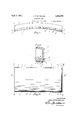
Objects, advantages and features of the invention will appear in the description of the drawings forming a part of this application, and in'said drawings Figure 1 is an end elevation of a pressing head constructed according to the teachings of this invention, with part of a facing strip broken away;
Figure 2 is a detail section showing the manner of applying force to secure the facing plate in arched condition;
' Figure 3 is a view of the form illustrated in Figure 1, looking at the top side and illustrating the relation of the locking or tensioning strips, to those of the finishin cement layer-retaining strips which extend longitudinally of the device;
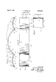
, Figure 4 is an elevation showing the infill ures 3 and 4, showing that side opposite the working face, and illustrating the relation of the clamping strips to the finishing strips.
In carrying out my invention, I form the head 1 in any preferred manner, as by casting, to provide the usual steam space 2, and a concave working face 3. Heretofore this working surface 3 has been machined as'by planing or milling, and has then been polished and buffed, and then nickel-plated and finally polished. This old method is a very expensive .one in which the heavy casting must be frequently handled, and which, if the surface is milled, requires a special millor having a working surface conforming to the curvature of the working surface of the head. If a planing operation is used, the planer must swing on an axis the center of which corresponds to the center of curvature of the working surface to be formed. Even after the working face has been produced by means of one of these old and expensive processes, the finished surface was not as perfect as could be desired. One of the difficulties, is that the texture of the metal used in casting is not sufficiently fine to allow the production of as smooth :1 working surface as is desired.
In the present method there is first applied to the rough cast surface 3, a plastic self-hardening material 4, having 9. highest possible heat-conducting ability. Strips or moldings 5 are then disposed longitudinally against the beveled surfaces 6, and secured by means of suitable fastening devices, in this instance headed screws 7. It will be noted that these plates project outwardly beyond the opposite parallel edges of the working surface, and when thus projected act as uides for a leveling device (not shown) by means of which the plastic material 8 is smoothed and leveled before application of the metal facing sheet 9. A straight edge may be used as a scraper. engaged against and moving along the projecting edge faces of the strips 5, in a manner to bridge the working face, and engage and remove that portion of the plastic material projecting beyond the strips. A facing substance of plastic cement-like nature is iron cement containing about ninety-five per cent of iron. v
For the finishin work-surfacereducing material, the face 0 the section of s eet metal is laid directly against the cement, and then this plate is pressed against the filling layer 8 by means of the elements 5 which are caused to clampingly engage the edges of the sheet as shown. When pressure is applied by the screws, the sheet is buckled or arched to compressively engage the layer. The locking strips 5 project slightly beyond the surface of the facing plate. This concave formation of the working face of the chest and the arrangement of the locking plates causes the sheet to act to compressively' seal, and retain the cement or filler. This is a valuable feature. Maximum heat conduction from the chest through the layer and through the polished plate is thus obtained. By the use of locking plate 5 to the corresponding face of the edgeof the finishing plate 9 is such that the plate is only compressed in a direction substantially parallel with its working surface, but the engaged edge is prevented from moving outwardly due to the angular abutting relation of the parts. This is a feature.
With a chest proportioned like that shown in Figure l, the locking strips 5 extend longitudinally of the ends of the chest. Other laterally arranged transversely extending strips 5 are employed, and the strips 5 are extended laterally as shown at 5", Figure 3, so as to overlap the finishing and retaining strips 5*. The strips 5 and 5 act together to retain the cement, the strips 5 acting also to apply the force to hold the facing plates in arched con- I dition compressively against the working face, or against a layer of heat-conducting material engaging that face.
By the use of the method hereln stock sheet metal may be used. Non-corrosive metal may be used, or other kinds of metal which are not corrosive can be used after bein coated with some non-corrosive material, an given a high finish by polishing.
As illustrated in Figures 4, 5 and 6, the invention may be applied to a presser head having a plurality of concave working surfaces. In this case at least one of the locking strips acts to apply the thrust to buckle two facing plates and secure them in arched condition with their face surfaces in intimate contact with the correspondin surface of the head, or of an interposed fil ing layer. The numeral 10 indicates the head, 11 the steam chambar and 12, 13 and 14 the concave working surfaces. The filler layers are indicated at 15, 16, 17 and the facing plates at 18, 19, 20. The locking strips or mouldin s are indicated at 21 and 22, and the fastening devices for these strips at 231 After the casting is completed, the threaded openings. are provided at 24 with which the fastening devices 23 are engageable. The centers of curvature of the surfaces 12, 13 and 14 lie on a common line.
In that form of the invention shown in Figures 4, 5 and 6, plates corresponding to facmg plates 5 are used a portion of one of the filler material 8.
thickness applied to said face,
plates being illustrated in side view in Figure 4. The plates may be made in sections so as to be separatel removable to expose the edges of only once the arch plates. These lates are designated 25 and are secured by suitable fastening devices 26. Figure 6 shows the relation of the strips or mouldings 21-25, in which the latter overlap the former. These strips cooperate in the same manner as strips 5 and 5 to form a kind of boxing to retain the iron cement when that is used.
It will be understood that the present invention provides means whereby the finishing late is held in a manner to have substantialy every portion of its facing surface intimately and compressively engaged under pressure with the corresponding surface of the heat conducting layer of plastic material which faces the concave surface of the steam chest or pressin head. In this manner, maximum heat con action from the steam chest througlithe head and its facing layers is obtaine It will be understood that other means may be employed to secure the facmg plate and maintain the pressure contact.
Referring to Figure 2, (and again to the angular abutting relation of parts 5 and 9),
it will be seen that the an le A which the beveled surface 6 makes wit the curved surface 3 of the castin 1 is somewhat greater than 90, as is also t e angle B between the inner surface of the element 5 and the workin surif ace of the finishing plate 9 at point 0 contact with plate 5. herefore, the angular relations are such that pressure is applied at the edge ofthe plate 9 in a manner to always push it upwardly toward the surface 3 throu hout all its portions, and a wedge is thus ormed to prevent movement of that edge which is engaged by the clam g late 5, in a direction aw iiifrom the surace d and s is an important feature of the invention.
I claim as my invention:
1. A pressing head having a concave workmg face, a fac n coat of molded heat conducting materia of substantially uniform a finishing plate, and means appllving force against a pair of opposite edge aces of said plate to arch 1t and cause it-to eompreesively and flatly engage and heat wnducting material. 2. A pressing head he a concave workmg face, a coat of heatmo dable conducting material of substantially uniform thickness applied to said face, a finishing plate,'and means applying force against a pair of opposite edge faces late to arch it and cause its face to mt y contact the face of said heat co i material.
3 A method fo -ucing a pressing head which lips a lug y polished working surface, which in producing a castin having a can neg, applying moldab e heat-conducting material to said curved face to form a layer of substantiallyuniform thickness, finishin and polishing one face of a late of flexi 1e metal while flat, and then Boxing the plate and causin it to engage and conform to the surface 0 the lastic material, with the polished face 0 the plate facing outwardly.
4. A pressing head having a curved face, a coat of plastic heat conducting material of substantially uniform thickness coverin said surface, a flexed plate of thin metal in acial contact with said material, and means a Jlying pressure to said plate to hold it in exed condition and compressivcly a ainst said coat and secure it to said head, sai plate having an exposed working face which is
Priority Applications (1)
| Application Number | Priority Date | Filing Date | Title |
|---|---|---|---|
| US381772A US1852374A (en) | 1929-07-29 | 1929-07-29 | Pressing head |
Applications Claiming Priority (1)
| Application Number | Priority Date | Filing Date | Title |
|---|---|---|---|
| US381772A US1852374A (en) | 1929-07-29 | 1929-07-29 | Pressing head |
Publications (1)
| Publication Number | Publication Date |
|---|---|
| US1852374A true US1852374A (en) | 1932-04-05 |
Family
ID=23506298
Family Applications (1)
| Application Number | Title | Priority Date | Filing Date |
|---|---|---|---|
| US381772A Expired - Lifetime US1852374A (en) | 1929-07-29 | 1929-07-29 | Pressing head |
Country Status (1)
| Country | Link |
|---|---|
| US (1) | US1852374A (en) |
Cited By (2)
| Publication number | Priority date | Publication date | Assignee | Title |
|---|---|---|---|---|
| DE1124008B (en) * | 1953-06-05 | 1962-02-22 | Paulsen & Co G M B H | Drying ironing device |
| DE1216235B (en) * | 1961-06-07 | 1966-05-12 | Franz Walterscheid G M B H | Trough-type mangle with an input table and an output table as well as with an ironing surface |
-
1929
- 1929-07-29 US US381772A patent/US1852374A/en not_active Expired - Lifetime
Cited By (2)
| Publication number | Priority date | Publication date | Assignee | Title |
|---|---|---|---|---|
| DE1124008B (en) * | 1953-06-05 | 1962-02-22 | Paulsen & Co G M B H | Drying ironing device |
| DE1216235B (en) * | 1961-06-07 | 1966-05-12 | Franz Walterscheid G M B H | Trough-type mangle with an input table and an output table as well as with an ironing surface |
Similar Documents
| Publication | Publication Date | Title |
|---|---|---|
| US2110728A (en) | Construction material and method of making same | |
| CA2685801C (en) | Plate press | |
| US1852374A (en) | Pressing head | |
| US2310619A (en) | Manufacture of hard rubber panels | |
| US2581602A (en) | Tool slide | |
| US2192133A (en) | Casting press | |
| US1715772A (en) | Assiotob to the batjeb brothers | |
| US1649876A (en) | Method of making electrotypes | |
| US2118801A (en) | Process of finishing printing plates | |
| CN210616174U (en) | Exempt from to revise wear-resisting bottom plate and polisher | |
| US2013949A (en) | Rubber die | |
| US685204A (en) | Appliance for fixing sheets of glass for grinding, polishing, or other operations. | |
| US1509079A (en) | Brick-machine mold | |
| US3836A (en) | Stereotyping | |
| US1384506A (en) | Antirattling device for automobile-doors and the like | |
| US304976A (en) | traylor | |
| US980882A (en) | Grinding-machine. | |
| US1101046A (en) | Runner for grinding plate-glass. | |
| US992121A (en) | Method of preparing printing-plates for bending. | |
| US326376A (en) | allen | |
| US1629931A (en) | Plate for vacuum pumps | |
| US1603516A (en) | Wheel for finishing stone | |
| US632908A (en) | Tile structure. | |
| US2226058A (en) | Mold jacket | |
| US1564924A (en) | Manufacture of molds for making concrete or like beams, blocks, columns, and the like |