US1852369A - Traffic controlling system for railroads - Google Patents
Traffic controlling system for railroads Download PDFInfo
- Publication number
- US1852369A US1852369A US465611A US46561130A US1852369A US 1852369 A US1852369 A US 1852369A US 465611 A US465611 A US 465611A US 46561130 A US46561130 A US 46561130A US 1852369 A US1852369 A US 1852369A
- Authority
- US
- United States
- Prior art keywords
- switch
- spring
- points
- signal
- pressure
- Prior art date
- Legal status (The legal status is an assumption and is not a legal conclusion. Google has not performed a legal analysis and makes no representation as to the accuracy of the status listed.)
- Expired - Lifetime
Links
Images
Classifications
-
- B—PERFORMING OPERATIONS; TRANSPORTING
- B61—RAILWAYS
- B61L—GUIDING RAILWAY TRAFFIC; ENSURING THE SAFETY OF RAILWAY TRAFFIC
- B61L21/00—Station blocking between signal boxes in one yard
- B61L21/06—Vehicle-on-line indication; Monitoring locking and release of the route
Definitions
- This invention relates to traflic controlling systems or devices for railroads, and more particularly to a safety device for spring switches.
- the switch points are held in one position, usually the normal position, by a heavy spring which acts to return the points automatically to the normal position when the switch is 1 trailed, a suitable oil dash-pot or the like being usually employed to retard such return movement and prevent shifting and pounding of the switch points as the successive wheels of a train pass through the switch in direction.
- a heavy spring which acts to return the points automatically to the normal position when the switch is 1 trailed
- a suitable oil dash-pot or the like being usually employed to retard such return movement and prevent shifting and pounding of the switch points as the successive wheels of a train pass through the switch in direction.
- train movements over such a spring switch in the facing direction should be made at low speeds. This frequently causes delays in train operation, which would be avoided if the trains could move over a spring switch in the facing direction at normal speeds.
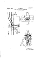
- Fig. 1 il- 0 lustrates diagrammatically one arrangement of devices and circuits, embodying the in- 1930.
- Fig. 2 shows a longitudinal section of one specific form of the pressure responsive circuit controlling means of this invention.
- Fig. 3 illustrates diagrammatically a modilied construction of the pressure responsive circuit controlling device.
- the switch SW is assumed to be of the usual and well-known construction having an insulated front rod F, to which is connected the usual spring and dashpot mechanism S, and the switch stand or hand-throw device HT.
- a suitable pressure responsive circuit controlling device A is included in the mechanical connections between the spring mechanism S and the switch points.
- this device A in the form shown is fastened to the front rod F, and is connected to the rod or bar 4 extending to the spring mechanism S. Any other desired arrangement may be employed, so long as the pressure responsive device A detects the pressure or force acting against the switch points.
- Train movements over the switch SW are governed by a signal 1, which in turn is controlled by a line or signal relay 1 HD.
- This signal 1 is shown conventionally as a threeposition semaphore signal, but may be a colorlight signal, or a signal of any other suitable type.
- the line relay 1 HD as shown, is a neutral-polar relay, controlling the semaphore l in the usual way through a neutral contact 5 and a polar contact 6. Neutral home and distant relays and various other arrangements of controlling circuits for the signal 1, in accordance with recognized practice. may be employed.
- the energizing circuit for the relay 1 HD may be traced from (C), indicating a connection to the usual common wire, through the relay 1 HD, wire 7, front contact 8 of the usual detector track relay, wire 9, contacts 10 of the usual switch circuit controller of the switch SW, these contacts being closed only in the normal position of this switch, wire 11, through the pressure responsive circuit controlling device A,
- a casting 15 of a general cylindrical shape and constituting the supporting casing or housing of the device is formed with a flange 15 to be bolted to the front rod F.
- an adjusting bolt or plug 16 which engages one end of a heavy coil spring 17.
- the other end of the spring 17 engages a circular head 18, guided in a cylindrical recess at the end of the casting 15; and fixed to this head 18 is the rod or bar 4:. which is connected to the spring mechanism S.
- a sleeve 19, of suitable insulated material, is fastened to the rod 1; and.
- a metallic contact ring 20 co-operating' with spring contact fingers 21.
- These contact fingers 21 are attached to and supported by insulated binding posts 22, which are supported in a cap 23, secured by bolts 24 to the casting 15.
- a washer 25 of felt or similar material. forms a dirt-tight connection between the cap" 23 and rod 4.
- the spring mechanism S If the spring mechanism S is in proper order and is transmitting a pressure or force. in the direction indicated by the arrow a in Fig. 2, to hold the switch points in the normal position, the parts are in the position shown in Fig. 2, the spring 17 being compressed. and the contact ring 20 engaging the contact finger 21 to establish an electrical connection between the wires 11 and 12 and permit energization of the relay 1 HD to clear the signal 1. If, however, the parts of the spring mechanism S are broken, or if for any other reason, a predetermined pressure is not being transmitted from the rod 4 to the switch points, the spring 17 expands and opens the contacts 2021, and, causes signal 1 to indicate stop. The tension of the spring 17 is set by the adjusting plug 16, so that when this spring is compressed, as shown in Fig. 2, the pressure acting on the switch points is sufficient to permit train movement over the switch in the facing, direction at the normal running speeds.
- a train may safely pass over the switch SV in the facing direction at full speed, since the usual switch circuit controller contacts 10, being closed, show that the switch points are in the full normal position, and the contacts 20-2l being closed, show that a predetermined pressure or force, suflicient to compress the spring 17, is acting to hold the switch points in this normal position.
- the rod 4 connected to the spring mechanism S is formed with, or has attached thereto, a flat rectangular head 30, provided with a longitudinal slot 31 with enlarged ends, the material of the head and its dimensions being selected and proportioned so that the two side portions of the head 30, on opposite sides of the slot 31 may be pressed together a short distance by a predetermined pressure, and will resume the normal position when this pressure is released.
- a bar or rod 32, connected to the switch points, is suitably fastened to one side portion of the head 30 in line with the rod 4.
- a pressure-responsive circuit controlling device comprising a carbon block 33, metallic plates 34, bearing against opposite faces of the carbon block, and insulated plates 35, the wires 11 and 12 of the energizing circuit for the relay 1 HD being connected to the metallic plates 34.
- the predetermined desired pressure is acting to hold the switch points, the side portions of the head 30 are forced together sufliciently to compress the carbon block 33, lower its resistance, and permit sufficient current to flow to energize the relay 1 HD. If, however, this predetermined pressure is not acting to hold the switch points, pressure is not applied to the carbon block 33, and it interposes sufficient resistance in the energizing circuit for the relay 1 HD to prevent thisrelay attracting its armature.
- Fig. 3 This modified construction of Fig. 3 is preferably provided with a suitable housing or casing (not shown) and in both arrangements, the wires 11 and 12 are flexible and suitably protected, so that the switch points may be shifted to the reverse position by the switch stand HT, or by a trailing train movement.
- this invention provides means for detecting if a predetermined and safe pressure is acting to hold the points of a track switch in the normal position.
- This detecting means may be employed in various ways to govern train movement over the switch; and while this detecting means is especially applicable to a spring switch, it may be advantageously employed in connection with any hand or power-operated track switch.
- circuit controlling means effecin the connection between said operating forced toward each other by a force greater means and the switch points and responsive than that of said spring.
- a railway trafiic controlling system the combination with a track switch, spring means to hold said switch in the normal position, a signal governing trafiic in the facing direction over said switch, a circuit acting when opened to cause said signal to indicate stop, and circuit controlling means in said circuit effectively closed only if said spring means is acting to exert a predetermined pres sure to hold the switch points in their normal position.
- a traflic controlling system the combination with a track switch, means for op erating the switch, and circuit controlling means included in the connection between said switch and its operating means, said circuit controlling means being responsive to the pressure acting to hold the switch points in one position.
- a pressure responsive circuit controlling device comprising, two members movable relatively only by a predetermined force, one of said members being connected to the switch points and the other to said operating means.
Landscapes
- Engineering & Computer Science (AREA)
- Mechanical Engineering (AREA)
- Train Traffic Observation, Control, And Security (AREA)
Description
April 5, 1932. N. D. PRESTON TRAFFIC CONTROLLING SYSTEM FOR RAILROADS Filed July 3, 1950 the trailing Patented Apr. 5, 1932 UNITED STATES PATENT OFFICE NEIL D. PRESTON,
OF ROCHESTER, NEW YORK, ASSIGNOR TO GENERAL RAILWAY SIGNAL COMPANY, OF ROCHESTER, NEW YORK TRAFFIC CONTROLLING SYSTEM FOR RAILROADS Application filed July 3,
This invention relates to traflic controlling systems or devices for railroads, and more particularly to a safety device for spring switches.
In the well-known spring switch, the switch points are held in one position, usually the normal position, by a heavy spring which acts to return the points automatically to the normal position when the switch is 1 trailed, a suitable oil dash-pot or the like being usually employed to retard such return movement and prevent shifting and pounding of the switch points as the successive wheels of a train pass through the switch in direction. Since the spring mechanism or some of its connections to the switch may be bent or broken, so that the switch points are not properly held and may be displaced by the wheels of the train and cause derailment, train movements over such a spring switch in the facing direction should be made at low speeds. This frequently causes delays in train operation, which would be avoided if the trains could move over a spring switch in the facing direction at normal speeds.
In accordance with this invention, it is proposed to provide suitable means for detecting if the spring of a spring switch is acting to hold the switch points in the normal position with a predetermined pressure, sufficient to permit train movements in the facing direction at high speeds.
35 Stated more specifically, it is proposed to include a suitable pressure responsive circuit controlling means in the connections between the switch points andthe spring acting on these points, and employ this circuit con- 4 trolling means to control a signal governing trailic over the switch in the same direction, so that this signal may clear only if a predetermined force of pressure is acting to hold the switch points.
Other characteristic features and advantages of the invention will be in part apparent, and in part pointed out, as the description progresses.
In the accompanying drawings, Fig. 1 il- 0 lustrates diagrammatically one arrangement of devices and circuits, embodying the in- 1930. Serial No. 465,611.
vention, applied to a spring switch of the usual construction;
Fig. 2 shows a longitudinal section of one specific form of the pressure responsive circuit controlling means of this invention; and
Fig. 3 illustrates diagrammatically a modilied construction of the pressure responsive circuit controlling device.
Referring to Fig. 1, the switch SW is assumed to be of the usual and well-known construction having an insulated front rod F, to which is connected the usual spring and dashpot mechanism S, and the switch stand or hand-throw device HT. In accordance with this invention, a suitable pressure responsive circuit controlling device A is included in the mechanical connections between the spring mechanism S and the switch points. As illustrated diagrammatically in Fig. 1, this device A in the form shown is fastened to the front rod F, and is connected to the rod or bar 4 extending to the spring mechanism S. Any other desired arrangement may be employed, so long as the pressure responsive device A detects the pressure or force acting against the switch points.
Train movements over the switch SW are governed by a signal 1, which in turn is controlled by a line or signal relay 1 HD. This signal 1 is shown conventionally as a threeposition semaphore signal, but may be a colorlight signal, or a signal of any other suitable type. The line relay 1 HD, as shown, is a neutral-polar relay, controlling the semaphore l in the usual way through a neutral contact 5 and a polar contact 6. Neutral home and distant relays and various other arrangements of controlling circuits for the signal 1, in accordance with recognized practice. may be employed.
The energizing circuit for the relay 1 HD, as partially shown, may be traced from (C), indicating a connection to the usual common wire, through the relay 1 HD, wire 7, front contact 8 of the usual detector track relay, wire 9, contacts 10 of the usual switch circuit controller of the switch SW, these contacts being closed only in the normal position of this switch, wire 11, through the pressure responsive circuit controlling device A,
Referring to Fig. 2', which shows one specific form of a pressure responsive circuit controlling means, a casting 15 of a general cylindrical shape and constituting the supporting casing or housing of the device, is formed with a flange 15 to be bolted to the front rod F. In one end of the casting 15 is threaded an adjusting bolt or plug 16, which engages one end of a heavy coil spring 17. The other end of the spring 17 engages a circular head 18, guided in a cylindrical recess at the end of the casting 15; and fixed to this head 18 is the rod or bar 4:. which is connected to the spring mechanism S. A sleeve 19, of suitable insulated material, is fastened to the rod 1; and. secured to this sleeve 19 is a metallic contact ring 20 co-operating' with spring contact fingers 21. These contact fingers 21 are attached to and supported by insulated binding posts 22, which are supported in a cap 23, secured by bolts 24 to the casting 15. A washer 25 of felt or similar material. forms a dirt-tight connection between the cap" 23 and rod 4.
If the spring mechanism S is in proper order and is transmitting a pressure or force. in the direction indicated by the arrow a in Fig. 2, to hold the switch points in the normal position, the parts are in the position shown in Fig. 2, the spring 17 being compressed. and the contact ring 20 engaging the contact finger 21 to establish an electrical connection between the wires 11 and 12 and permit energization of the relay 1 HD to clear the signal 1. If, however, the parts of the spring mechanism S are broken, or if for any other reason, a predetermined pressure is not being transmitted from the rod 4 to the switch points, the spring 17 expands and opens the contacts 2021, and, causes signal 1 to indicate stop. The tension of the spring 17 is set by the adjusting plug 16, so that when this spring is compressed, as shown in Fig. 2, the pressure acting on the switch points is sufficient to permit train movement over the switch in the facing, direction at the normal running speeds.
Thus, if the signal 1 indicates clear, a train may safely pass over the switch SV in the facing direction at full speed, since the usual switch circuit controller contacts 10, being closed, show that the switch points are in the full normal position, and the contacts 20-2l being closed, show that a predetermined pressure or force, suflicient to compress the spring 17, is acting to hold the switch points in this normal position.
In the modified construction shown in Fig. the rod 4, connected to the spring mechanism S, is formed with, or has attached thereto, a flat rectangular head 30, provided with a longitudinal slot 31 with enlarged ends, the material of the head and its dimensions being selected and proportioned so that the two side portions of the head 30, on opposite sides of the slot 31 may be pressed together a short distance by a predetermined pressure, and will resume the normal position when this pressure is released. A bar or rod 32, connected to the switch points, is suitably fastened to one side portion of the head 30 in line with the rod 4.
Supported in any suitable Way in the slot 31 of the head 30 is a pressure-responsive circuit controlling device, comprising a carbon block 33, metallic plates 34, bearing against opposite faces of the carbon block, and insulated plates 35, the wires 11 and 12 of the energizing circuit for the relay 1 HD being connected to the metallic plates 34.
WVhen the predetermined desired pressure is acting to hold the switch points, the side portions of the head 30 are forced together sufliciently to compress the carbon block 33, lower its resistance, and permit sufficient current to flow to energize the relay 1 HD. If, however, this predetermined pressure is not acting to hold the switch points, pressure is not applied to the carbon block 33, and it interposes sufficient resistance in the energizing circuit for the relay 1 HD to prevent thisrelay attracting its armature.
This modified construction of Fig. 3 is preferably provided with a suitable housing or casing (not shown) and in both arrangements, the wires 11 and 12 are flexible and suitably protected, so that the switch points may be shifted to the reverse position by the switch stand HT, or by a trailing train movement.
From the foregoing it can be seen that this invention provides means for detecting if a predetermined and safe pressure is acting to hold the points of a track switch in the normal position. This detecting means may be employed in various ways to govern train movement over the switch; and while this detecting means is especially applicable to a spring switch, it may be advantageously employed in connection with any hand or power-operated track switch.
Various adaptations, modifications, and additions may be made in the particular construction and arrangement of parts and circuits shown and described without departing "from the invention.
What I claim is 1. In a railway trafiic controlling system, the combination with a track switch, a signal governing trafiic over said switch, operating means for moving said switch to and holding spring, and means included tively closed only when said members are it in a normal position,
and circuit controlling means effecin the connection between said operating forced toward each other by a force greater means and the switch points and responsive than that of said spring.
to the pressure transmitted by said operating means against the points of said switch for controlling said signal, whereby said signal is caused to indicate stop unless the switch points are held in the normal position by a predetermined pressure.
2. In a railway trafiic controlling system, the combination with a track switch, spring means tending to hold said switch in the normal position, a signal governing traflic in the facing direction over said switch, and means for causing said signal to indicate stop unless a predetermined pressure is acting to hold the points of said switch in the normal position.
3. In a railway trailic controlling system, the combination with a track switch, spring means to hold said switch in the normal position, a signal governing trafiic in the facing direction over said switch, pressure responsive means included in the connection between the switch points and said spring means for causing said signal to indicate stop unless a predetermined pressure is acting to hold the switch points in their normal position.
4. In a railway trafiic controlling system, the combination with a track switch, spring means to hold said switch in the normal position, a signal governing trafiic in the facing direction over said switch, a circuit acting when opened to cause said signal to indicate stop, and circuit controlling means in said circuit effectively closed only if said spring means is acting to exert a predetermined pres sure to hold the switch points in their normal position.
5. In a traflic controlling system, the combination with a track switch, means for op erating the switch, and circuit controlling means included in the connection between said switch and its operating means, said circuit controlling means being responsive to the pressure acting to hold the switch points in one position.
6. In a device of the character described, the combination with a track switch, operating means for the switch, a pressure responsive circuit controlling device comprising, two members movable relatively only by a predetermined force, one of said members being connected to the switch points and the other to said operating means.
7. In a device of the character described, the combination with a track switch, operating means for the switch, two relatively movable members, one of said members being connected to the points of said switch, the other member being connected to said operating means, a spring tending to move said members apart, means for adjusting the tension of said In testimony whereof I aflix my signature.
NEIL D. PRESTON.
Priority Applications (1)
| Application Number | Priority Date | Filing Date | Title |
|---|---|---|---|
| US465611A US1852369A (en) | 1930-07-03 | 1930-07-03 | Traffic controlling system for railroads |
Applications Claiming Priority (1)
| Application Number | Priority Date | Filing Date | Title |
|---|---|---|---|
| US465611A US1852369A (en) | 1930-07-03 | 1930-07-03 | Traffic controlling system for railroads |
Publications (1)
| Publication Number | Publication Date |
|---|---|
| US1852369A true US1852369A (en) | 1932-04-05 |
Family
ID=23848460
Family Applications (1)
| Application Number | Title | Priority Date | Filing Date |
|---|---|---|---|
| US465611A Expired - Lifetime US1852369A (en) | 1930-07-03 | 1930-07-03 | Traffic controlling system for railroads |
Country Status (1)
| Country | Link |
|---|---|
| US (1) | US1852369A (en) |
-
1930
- 1930-07-03 US US465611A patent/US1852369A/en not_active Expired - Lifetime
Similar Documents
| Publication | Publication Date | Title |
|---|---|---|
| US1702997A (en) | Signal-control apparatus | |
| US1852369A (en) | Traffic controlling system for railroads | |
| US1787752A (en) | Railway signal system | |
| US2092021A (en) | Speed selective control system | |
| US1187586A (en) | Electric railway-signal and appertaining mechanism. | |
| US1146993A (en) | Block-signal apparatus. | |
| US1296361A (en) | Highway-crossing signal. | |
| US2547626A (en) | Apparatus for controlling highway crossing signals | |
| US627245A (en) | Railway-signal | |
| US1980084A (en) | Power-operated lock for spring switches | |
| US643609A (en) | Signaling system. | |
| US1003143A (en) | Electric signaling apparatus. | |
| US1229345A (en) | Directional trolley-contactor. | |
| US1399725A (en) | Signaling system for single-track railroads | |
| US2216483A (en) | Railway traffic controlling apparatus | |
| US1232859A (en) | Train signaling and stopping system. | |
| US1195748A (en) | sutphin | |
| US1768668A (en) | Automatic electrically-operated derail | |
| US1031529A (en) | Block-signaling system and safety apparatus. | |
| US1124067A (en) | Automatic train-braking system. | |
| US1190015A (en) | Train-stopping mechanism. | |
| US1179293A (en) | Selective relay. | |
| US1824143A (en) | Automatic train stop | |
| US2129310A (en) | Apparatus for the control of highway crossing signals | |
| US545494A (en) | Bail way block signal system |