US1852359A - Stand for hectograph duplicating machines - Google Patents
Stand for hectograph duplicating machines Download PDFInfo
- Publication number
- US1852359A US1852359A US270874A US27087428A US1852359A US 1852359 A US1852359 A US 1852359A US 270874 A US270874 A US 270874A US 27087428 A US27087428 A US 27087428A US 1852359 A US1852359 A US 1852359A
- Authority
- US
- United States
- Prior art keywords
- carrier
- stand
- main frame
- frame
- roll
- Prior art date
- Legal status (The legal status is an assumption and is not a legal conclusion. Google has not performed a legal analysis and makes no representation as to the accuracy of the status listed.)
- Expired - Lifetime
Links
- 108010010803 Gelatin Proteins 0.000 description 34
- 229920000159 gelatin Polymers 0.000 description 34
- 239000008273 gelatin Substances 0.000 description 34
- 235000019322 gelatine Nutrition 0.000 description 34
- 235000011852 gelatine desserts Nutrition 0.000 description 34
- 230000033001 locomotion Effects 0.000 description 19
- 238000010276 construction Methods 0.000 description 5
- 238000005266 casting Methods 0.000 description 4
- 235000000396 iron Nutrition 0.000 description 3
- 230000013707 sensory perception of sound Effects 0.000 description 2
- XLYOFNOQVPJJNP-UHFFFAOYSA-N water Substances O XLYOFNOQVPJJNP-UHFFFAOYSA-N 0.000 description 2
- 241000283690 Bos taurus Species 0.000 description 1
- 229910000746 Structural steel Inorganic materials 0.000 description 1
- ATJFFYVFTNAWJD-UHFFFAOYSA-N Tin Chemical compound [Sn] ATJFFYVFTNAWJD-UHFFFAOYSA-N 0.000 description 1
- 230000000717 retained effect Effects 0.000 description 1
Images


Classifications
-
- B—PERFORMING OPERATIONS; TRANSPORTING
- B41—PRINTING; LINING MACHINES; TYPEWRITERS; STAMPS
- B41L—APPARATUS OR DEVICES FOR MANIFOLDING, DUPLICATING OR PRINTING FOR OFFICE OR OTHER COMMERCIAL PURPOSES; ADDRESSING MACHINES OR LIKE SERIES-PRINTING MACHINES
- B41L9/00—Apparatus for indirectly duplicating from hectographic originals by means of hectographic intermediaries or transfer surfaces, i.e. "dry duplicators"
- B41L9/04—Apparatus for indirectly duplicating from hectographic originals by means of hectographic intermediaries or transfer surfaces, i.e. "dry duplicators" with flat supports over which gelatin-paper is stretched
Definitions
- the ob ect of the invention is to rovide a i novel stand of simple construction for supall porting a hectograph duplicating machine and a: plurality of gelatin band rolls in convenient po ion with relation to the machine for succe; e use therein.
- Another object of the invention is to provide a stand for a hectograph duplicating machine with carrier means for supporting a plurality of gelatin band rolls and adapted to be operated to bring the rolls successively into position for use in the machine.
- rind further objects of the invention are to provide simple means for supporting, guiding; and protecting the roll carrier; to pro vide simple and easily operated means for feeding: the roll carrier to bring; a fresh roll into operative relation to the duplicatingma chine when required; and to provide simple means for insuring; a uniform feeding movement of the roll carrier, and to prevent rev vrec movement of the carrier.
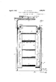
- Fig: l is a perspective view of my improved stand w th a hectogrraph duphcating machine indimted in broken lines thereon.
- Fin. 2 is an elevation of the rear end of the machine where the carrier and its supply of ro s are located. This view being partly brohen away and in section.
- t e. 23 is a side elevation of the stand, K .'.n section and with the side shield broken away.
- FIG. 4 is a detail sectional view showing the grindingand feeding devices at the lower end of the roll carrier.
- Fin. 5 is a detail sectional view on the line --5 of Fig.2. 3.
- FIG. 6 is a transverse sectional view on the line 6-4) of Fig. 3.
- l ip 7 is an enlarged detail view. partly on showing one of the roll hangers. ferringr to the drawings the stand comprises a skeleton main frame 8 which may he made conveniently out of tubular stock ALL DUPLICATING MACHINES 1928. Serial No. 270,874.
- a carrier frame is supported on the main frame at the rear end thereof to receive the endless bolts 11.
- the carrier frame is conveniently made of angle irons 12 tied together by strips 13 and having an upper end casting 14 and a lower end casting 15, these end castings being bolted or otherwise fastened to the angle iron intermediate portion of the carrier frame.
- the outer flange 16 of the angle irons of the carrier frame forms a track for the endless belts 11, and the castings are made to form a substantial continuation of thistrack, being provided with anti-friction rollers 17 at the upper corners and at one lower corner on which the belts travel about these corners.
- These rollers are preferably grooved at 17, Fig. 5 and the angle irons are grooved at 16", Figs. 6-7, to receive projections 18 on the belts whereby the belts are guided and retained in their proper operative position on the carrier frame.
- the gelatin band is attached at its ends to two spindles 19, 19', Fig. 7, which alternate as supply and takeup spindles.
- the two spindles are mounted at their ends in hangers 20 which are pivotally supported on the carrier.
- One: satisfactory means of mounting the hangers on the carrier is shown in Fig. 7 and comprises a sleeve 21 welded or otherwise permanent-1y fastened to the belt, transversely thereof, a bearing sleeve 22 arranged in the carrier sleeve 21 and a pin 23 pivotally secured in the hanger 20 and in the bearing sleeve 22, and headed at its ends. Mounting the hangers as described enables the hanger to freely swing on its pivot and maintain upright position in passing around the corners of the carrier frame.
- the hangers may be made in any suitable form for en gaging and supporting spindles of different kinds.
- Inward projections 24 may be provided at the lower end of the hangers to on page lugs 25 on the journal ends of the spin dle, as disclosed in my Patent No. 1,742,270. patented. January 7 1930; and the upper end of the hangers may be bent inwardly at 20 and slotted at 26 to receive the journals 2? of the upper spindle 19.
- the carrier close to the rear end of the duplicating machine so that the upper roll in the carrier adjacent the rear end of the machine will be conveniently disposed. for transfer from the carrier to the machine.
- the top right hand roll, Fig. 3 is ready to be inserted in the duplicating machine. After it has been used it will be returned to the same position it now occupies in Fig. 3. Then the carrier will be operated to move forward in a counterclockwise direction to carry'the used roll away from transfer position, to the left in Fig. 3, and to bring the next roll into transfer position, so that it can be taken from the carrier and placed in the duplicating machine.
- the arrangement is such that this transfer from the carrier to the machine and back to the carrier can be easily and conveniently accomplished by anyone capable of operating theduplicating machine, and the construction is such that no difliculty will be experienced in removing the roll from the carrier and replacing the roll therein with its spindles properly engaged with the hangers.
- Y As a protection for the carrier and the ends of the rolls, and also to prevent removal of the rolls at the rear of the stand I provide side shields which are secured to the sides of the main frame and comprise side plates 28 and inturned flanges 29 whichoverlap the ends of the rolls, Fig. 1.
- Drive wheels 30 are rigidly mounted on a transverse shaft 31 which is supported in the main frame adjacent the bottom of the carrier frame. These drive wheels may be variously constructed for operative engagement with the belts 11, but I prefer to provide the wheels with pins 32 toengage holes 33 in the belts, Figs. 5, 6, whereby both belts will be fed uniformly and positively whenever the drive wheels are operated.
- a pinion 3a is loosely mounted on the shaft 31 within a housing 35 on the main frame, Fig. 3, and this pinion operatively engage a rack bar 36 which is guided in the housing.
- a spring 37 is con nected to the upper end of this rack bar and to the carrier frame, and the lower end of the rack bar has a lateral projection 38 thereon which constitutes a pedal or foot piece whereby the rack bar can be caused to travel downward by foot pressure applied to the projeotion.
- a ratchet wheel 39 is rigid with the pinion 34 on the shaft 31 and a pawl a0 is pivotally mounted onthe drive wheel 30 and is held by a spring ll in operative engagement with the ratchet wheel so that downward movement of the rack bar will be communicated through the pinion, the ratchet wheel, and the pawl to one drive wheel 30 and from said drive wheel 30 through the shaft 31 to the other drive wheel 30.
- the rack bar 38 When pressure on the rack bar 38 is released and the spring 37 returns the rack bar to its normal up position the ratchet wheel turns freely in a reverse direction under the pawl and the carrier remains stationary. Thus the carrier is caused to travel on the downward movement of the rack bar, butremains stationary on the upward movement of the rack bar.
- a weighted locking pawl 42 w iich is pivoted at as on the housing 35 and is' arranged to engage a toothed bar L4- secured to tne sliding rack bar within the housing 35, Fig. 3.
- This toothed bar carries a finger which engages a pin -16 on thelocking dog 4'? pivotally mounted in he housing 35, Fig. 3. In normal position, when the sliding rack ar 36 is in up position, Fig. 3, the finger 45 has trai eled up far enough to disengage the locking dog i?
- My invention provides a convenient oiiice appliance of simple but strong and substantial construction which enables a supply of gelatin band rolls to be kept in convenient position with respect to the macnine so that rolls may be transferred between the supply and the machine with ease and convenience.
- the rolls are stored in the carrier for suce use, so that they will always be in prime condition for use and all the rolls will be in a uniform service condition.
- the carrier may be made in various ways to increase or decrease its capacity so that more rolls may be provided where the work re quires more rolls and, correspondingly, fewer rolls may be provided according to the work.
- My invention has the further advantage of associating the supply rolls with the machine in one compact arrangement. not only for the convenience in use, but for conserving floor space and wall space in an office, and for permitting the whole apparatus as a unit to be readily moved about from place to place in a room and from room to room as occasion may require.
- the moistening' device comprises a water receptacle which is supported in the stand, and a 1noistening roll which is carried by levers pivoted at 54 in the stand.
- the front portions 5:1 of the lovers are curved to reach over the rear top edge of the receptacle.
- the rear portions 56 of the levers carry a weight 57 which holds the moistening roller 53 in constant contact with the gelatin band roll 58 in themachine.
- a latch 59 is conveniently mounted on the stand and adapted to be engaged with a pin 60 to hold the weighted end of the lever up and the moistening roll down in the receptacle while the gelatin band roll is being changed.
- This feature of the invention is important because of the necessity for moistening the band and the desirability of having the moistening device located and constructed to Work automatically. All it is necessary to do to keep the moistening device functioning is to maintain a supply of Water in the receptacle.
- 'A stand for hectograph duplicating machines comprising ⁇ , a main frame, and a roll carrier unit including a frame mounted in the main frame and carrying a plurality of gelatin band rolls, component elements of said main frame providing a bed for removably supporting a hectograph duplicating machine.
- a stand for hectograph duplicating machines comprising a main frame, an endless carrier mounted in the mainframe for carryina a plurality of gelatin band rolls, and shields at-the sides of said carrier and having flanges overlapping the ends of said rolls.
- a stand for hectograph duplicating machines comprising a main frame, a roll carrier unit including a frame mounted in the main frame, an endless carrier operating in the carrier frame and carrying a plurality of gelatin band rolls, and means for operating the carrier intermittently.
- a stand for heotograph duplioating'machines comprising a main frame, a roll carrier unit including a frame mounted in the main frame, an endless carrier operating in the carrier frame, and means for supporting a gelatin band roll to pivot bodily in the carrier.
- a stand for hectograph duplicating machines comprising a main frame, a carrier frame mounted in the main frame, an endless carrier operating on the carrier frame, and means for supporting a unit to pivot bodily in the carrier and comprising; a pair of spindlcs and a gelatin band connected at its ends to said spindles and wound upon one of said spindles.
- a stand for hectograph duplicating machines comprising a main frame, a carrier frame mounted in the main frame, an endless carrier operating on the carrier frame, a pair of oppositely disposed hangers pivoted in the carrier and projecting on opposite sides of their pivots, and means on said hangers on opposite sides of their pivots for engaging and supporting a pair of spindles for a gelatin band roll.
- a stand for hectograph duplicating machines comprising a main frame, a carrier frame mounted in'the main frame, an endless carrier operating on the carrier frame, a pair of oppositely disposed hangers pivoted in the carrier, means on said hangers below their pivots for supporting a spindle with a gelatin band roll wound thereon, and means on said hangers above their pivots for supporting a spindle connected to the outer end of said gelatin band.
- A' stand for hectograph duplicating machines comprising a main frame, an endless carrier mounted in the main frame, oppositely disposed hangers pivotally mounted between their ends on the carrier, projections on said hangers below their pivots for engaging the ends of a roll spindle. said hangers being slot-ted above their pivots to receive journals of a spindle.
- a stand for hectograph duplicating machines comprising a main frame, a carrier frame mounted in the main frame, an endless carrier operating on the carrier frame, a pair of oppositely disposed sleeves on the carrier, and a pair of hangers pivotally mounted. in said sleeves and adapted to carry a gelatin band roll.
- a stand for hectograph duplicating machines comprising a main frame, a carrier frame mounted in the main frame, an endless carrier operating on the carrier frame. a pair of oppositely disposed sleeves mounted on said carrier. hearings in said sleeves and hangers pivoted in said bearings and adapted to carry a gelatin band roll.
- a stand for hectograph duplicating machines comprising a main frame, a carrier frame mounted in the main frame, an. endless carrier operating on the carrier frame,
- a pair of onpositelydisposed sleeves mounted on the carrier. hearings in said sleeves, pivot pins in said bearings and hangers mounted on said pivot pins and adapted to carry a gelatin band roll.
- a stand for hectograph duplicating machines comprising a main frame, an endless carrier mounted to travel in a substantially rectangular orbit in the main frame for carrying a plurality of gelatin band rolls,
- a stand for hectograph duplicating machines comprising a main frame, a carrier frame mounted in the main frame, a carrier operating on said carrier frame for carrying a plurality of gelatin band rolls and comprising a pair of endless belts, and means on the carrier frame and the belts for guiding the belts in their travel.
- a stand for hectograph duplicating machines comprising a main frame, a carrier frame mounted in said main frame, endless belts operating on said carrier frame for carrying a plurality of gelatin band rolls, said carrier frame having guide grooves, and projections on said belts arranged to travel in said grooves.
- a stand for hectograph duplicating machines comprising a main frame, a sub stantially rectangular frame mounted in the main frame, an endless carrier operating on said carrier frame for carrying a plurality of gelatin band rolls, and. a plurality of antifriction rollers mounted in the carrier frame at corners thereof and over which the carrier travels.
- a stand for hectograph duplicating machines comprising a main frame, an endless carrier mounted in the main frame for carrying a plurality of gelatin band rolls, means for imparting an intermittent move ment to said carrier, and means for preventing reverse movement of the carrier.
- a stand for hectograph duplicating machines comprising a main frame, an endless carrier mounted in the main frame for carrying a. plurality of gelatin band rolls, means for operating said carrier intermittently, and means for insuring a full move ment of said operating means.
- a stand for hectograph duplicating machines comprising a main frame, an endless carrier mounted in the main frame for carrying a plurality of gelatin band rolls, means for operating the carrier comprising a rack and pinion and ratchet device, and means for insuring a full movement of said device.
- a stand for hectograph duplicating machines comprising a mainframe, an endless carrier mounted in the main frame for carrying a plurality of gelatin band rolls, means for operating the carrier intermittently and comprising a rack and pinion and ratchet device, a projection on said rack to enable it to be operated by foot power, and locking means co-operating with said rack to prevent return movement of the rack until after it has completed a full initial movement.
- a stand for hectograph duplicating machines comprising a main frame, an endless carrier mounted in the main frame, means on the carrier for detachably holding a plurality of gelatin band rolls, and means for preventing rotative movement of the rolls in the holding means.
- a stand for hectograph duplicating machines comprising a main frame, a roll carrier unit including a frame mounted in the main frame and carrying a plurality of gelatin band rolls, component elements of said main frame providing a bed for removably supporting a hectograph duplicating machine, and a moistening device mounted in the main frame between the carrier frame and the machine supporting bed and adapted for cooperation with a gelatin band roll in the machine.
Landscapes
- Delivering By Means Of Belts And Rollers (AREA)
Description
April 5, 1932.
E. E. M NALLY STAND FOR HECTOGRAPH DUPLICA'IING MACHINES 3 Sheets-Sheet 1 Filed April 18. 1928 April 5, 1932. E. E. M NALLY STAND FOR HECTOGRAPH DUPLICATING MACHINES Filed April 18. 1928 5 Sheets-Sheet 2 mun rll IILIIrI I April 5, 1932.
E. E. M NALLY STAND FOR HECTOGRAPH DUPLICATING MACHINES I5 sheets-fiheet 3 Filed April 18, 1928 Patented Apr. 5, 1932 t STATES EDWARD E. MCITALLY, OF CHICAGO, ILLINOIS, ASSIGNOR 'IO JOHN J. FLANIGAN, F OAK PARK, ILLINOIS 1 STAND FOR HEGTOGlR-APH Application filed April 18,
tin band roll.
The ob ect of the invention is to rovide a i novel stand of simple construction for supall porting a hectograph duplicating machine and a: plurality of gelatin band rolls in convenient po ion with relation to the machine for succe; e use therein.
another object of the invention is to provide a stand for a hectograph duplicating machine with carrier means for supporting a plurality of gelatin band rolls and adapted to be operated to bring the rolls successively into position for use in the machine.
rind further objects of the invention are to provide simple means for supporting, guiding; and protecting the roll carrier; to pro vide simple and easily operated means for feeding: the roll carrier to bring; a fresh roll into operative relation to the duplicatingma chine when required; and to provide simple means for insuring; a uniform feeding movement of the roll carrier, and to prevent rev vrec movement of the carrier.
ll ith these and other ends in view I have shown the invention in a selected embodiment in the accompanying drawings wherein Fig: l is a perspective view of my improved stand w th a hectogrraph duphcating machine indimted in broken lines thereon.
Fin. 2 is an elevation of the rear end of the machine where the carrier and its supply of ro s are located. this view being partly brohen away and in section.
t e. 23 is a side elevation of the stand, K .'.n section and with the side shield broken away.
4 is a detail sectional view showing the grindingand feeding devices at the lower end of the roll carrier.
Fin. 5 is a detail sectional view on the line --5 of Fig.2. 3.
;'. 6 is a transverse sectional view on the line 6-4) of Fig. 3.
l ip 7 is an enlarged detail view. partly on showing one of the roll hangers. ferringr to the drawings the stand comprises a skeleton main frame 8 which may he made conveniently out of tubular stock ALL DUPLICATING MACHINES 1928. Serial No. 270,874.
in a light but strong, and substantial con.- struetion adapted to receive a hectograph duplicating machine 9 of any kind employing gelatin band rolls 1.0. A carrier frame is supported on the main frame at the rear end thereof to receive the endless bolts 11. The carrier frame is conveniently made of angle irons 12 tied together by strips 13 and having an upper end casting 14 and a lower end casting 15, these end castings being bolted or otherwise fastened to the angle iron intermediate portion of the carrier frame. The outer flange 16 of the angle irons of the carrier frame forms a track for the endless belts 11, and the castings are made to form a substantial continuation of thistrack, being provided with anti-friction rollers 17 at the upper corners and at one lower corner on which the belts travel about these corners. These rollers are preferably grooved at 17, Fig. 5 and the angle irons are grooved at 16", Figs. 6-7, to receive projections 18 on the belts whereby the belts are guided and retained in their proper operative position on the carrier frame.
The gelatin band is attached at its ends to two spindles 19, 19', Fig. 7, which alternate as supply and takeup spindles. The two spindles are mounted at their ends in hangers 20 which are pivotally supported on the carrier. One: satisfactory means of mounting the hangers on the carrier is shown in Fig. 7 and comprises a sleeve 21 welded or otherwise permanent-1y fastened to the belt, transversely thereof, a bearing sleeve 22 arranged in the carrier sleeve 21 and a pin 23 pivotally secured in the hanger 20 and in the bearing sleeve 22, and headed at its ends. Mounting the hangers as described enables the hanger to freely swing on its pivot and maintain upright position in passing around the corners of the carrier frame. The hangers may be made in any suitable form for en gaging and supporting spindles of different kinds. Inward projections 24; may be provided at the lower end of the hangers to on page lugs 25 on the journal ends of the spin dle, as disclosed in my Patent No. 1,742,270. patented. January 7 1930; and the upper end of the hangers may be bent inwardly at 20 and slotted at 26 to receive the journals 2? of the upper spindle 19. It will be readily understood that when the gelatin band roll, with the spindles attached to its ends, is removed from" the duplicating machine, the supply spindle can be readily engaged with the lower ends of the hangers and the takeup spindle with the upper ends of the hangers. The interengagement of the lugs on the lower ends of the hangers with the lugs on the journal ends of the supply spindle 19 will prevent the supply spindle from revolving while it remains in the carrierand therefore the gelatin band will always be in proper rolled condition while in the carrier.
I prefer to locate the carrier close to the rear end of the duplicating machine so that the upper roll in the carrier adjacent the rear end of the machine will be conveniently disposed. for transfer from the carrier to the machine. For example, the top right hand roll, Fig. 3, is ready to be inserted in the duplicating machine. After it has been used it will be returned to the same position it now occupies in Fig. 3. Then the carrier will be operated to move forward in a counterclockwise direction to carry'the used roll away from transfer position, to the left in Fig. 3, and to bring the next roll into transfer position, so that it can be taken from the carrier and placed in the duplicating machine. The arrangement is such that this transfer from the carrier to the machine and back to the carrier can be easily and conveniently accomplished by anyone capable of operating theduplicating machine, and the construction is such that no difliculty will be experienced in removing the roll from the carrier and replacing the roll therein with its spindles properly engaged with the hangers. Y As a protection for the carrier and the ends of the rolls, and also to prevent removal of the rolls at the rear of the stand I provide side shields which are secured to the sides of the main frame and comprise side plates 28 and inturned flanges 29 whichoverlap the ends of the rolls, Fig. 1. These shields sufficiently cover and enclose the carrier, the hangers and the ends of the rolls to form a protection therefor and to prevent the rolls from being removed from the carrier at the rear thereof. Drive wheels 30 are rigidly mounted on a transverse shaft 31 which is supported in the main frame adjacent the bottom of the carrier frame. These drive wheels may be variously constructed for operative engagement with the belts 11, but I prefer to provide the wheels with pins 32 toengage holes 33 in the belts, Figs. 5, 6, whereby both belts will be fed uniformly and positively whenever the drive wheels are operated. A pinion 3a is loosely mounted on the shaft 31 within a housing 35 on the main frame, Fig. 3, and this pinion operatively engage a rack bar 36 which is guided in the housing. A spring 37 is con nected to the upper end of this rack bar and to the carrier frame, and the lower end of the rack bar has a lateral projection 38 thereon which constitutes a pedal or foot piece whereby the rack bar can be caused to travel downward by foot pressure applied to the projeotion.
A ratchet wheel 39 is rigid with the pinion 34 on the shaft 31 and a pawl a0 is pivotally mounted onthe drive wheel 30 and is held by a spring ll in operative engagement with the ratchet wheel so that downward movement of the rack bar will be communicated through the pinion, the ratchet wheel, and the pawl to one drive wheel 30 and from said drive wheel 30 through the shaft 31 to the other drive wheel 30. When pressure on the rack bar 38 is released and the spring 37 returns the rack bar to its normal up position the ratchet wheel turns freely in a reverse direction under the pawl and the carrier remains stationary. Thus the carrier is caused to travel on the downward movement of the rack bar, butremains stationary on the upward movement of the rack bar. I v
To insure a uniform downward movement of the rack bar before it begins its return movement, I provide a weighted locking pawl 42 w iich is pivoted at as on the housing 35 and is' arranged to engage a toothed bar L4- secured to tne sliding rack bar within the housing 35, Fig. 3. This toothed bar carries a finger which engages a pin -16 on thelocking dog 4'? pivotally mounted in he housing 35, Fig. 3. In normal position, when the sliding rack ar 36 is in up position, Fig. 3, the finger 45 has trai eled up far enough to disengage the locking dog i? from the locking pawl 42 and the latter has swung into operative engagement with the toothed bar 44, so that on the downward movement of the rack bar and the toothed bar the locking pawl will constantly engage the toothed bar to prevent upward movement of the rack bar and the toothed bar until after the rack bar has completed. its full downward stroke. At this time the shoulder 44 on the toothed bar has disengaged the locking pavl from the toothed bar and the locking dog 4? has operatively engaged the locking pawl to hold the locking pawl away from the toothed bar. Pressure on the projection 38 having been withdrawn the spring 37 now returns the sliding rack bar and the toothed bar to normal up position, at or about the end of which the finger disengaged locking dog l? from locking pawl 4:2 which then swings into operative engagement with the toothed bar all.
The construction such and the parts are proportioned so that a complete downward movement of the rack bar will. insure sufficient travel of the carrier to bring a fresh roll into transfer position. Since the rack names bar cannot return to normal up position until after it has completed a full down stroke, the intermittent movement of the carrier will be uniform as to distance and at every movement of the carrier a fresh roll will be brought to the same transfer position.
My invention provides a convenient oiiice appliance of simple but strong and substantial construction which enables a supply of gelatin band rolls to be kept in convenient position with respect to the macnine so that rolls may be transferred between the supply and the machine with ease and convenience. The rolls are stored in the carrier for suce use, so that they will always be in prime condition for use and all the rolls will be in a uniform service condition. The carrier may be made in various ways to increase or decrease its capacity so that more rolls may be provided where the work re quires more rolls and, correspondingly, fewer rolls may be provided according to the work. I prefer that as many rolls be provided as will enable suflicient time to elapse between the use and the reuse of a roll to permit the ink to be completely absorbed by the gelatin to provide the band with a clear surface for use. My invention has the further advantage of associating the supply rolls with the machine in one compact arrangement. not only for the convenience in use, but for conserving floor space and wall space in an office, and for permitting the whole apparatus as a unit to be readily moved about from place to place in a room and from room to room as occasion may require.
I find it convenient to extend two tubes of the main frame above the rest of the stand and to bend. these tubes transversely at 48 across the top of the stand to carry a movable paper sheet support d9. A channel ,e'uidc 50 is secured on each transverse tube lS and T members 51 are secured to the under side of the support 49 and project into the channels of the guides 50. Rollers 52 on the support travel onv the guides. This support is a convenient means for carrying; a sup 'ily of sheets to be printed and the support can be easily moved to the left, Fin. to permit access to the rear end of the machine and to the carrier for transferring rolls between the machine and the carrier.
I prefer to provide the stand with a moistening device located and arranged for operative engagement with the gelatin roll in the machine so that when the machine is set in proper position on the stand the mois ening; device will make constant contact with the roll for moistening the band. The moistening' device comprises a water receptacle which is supported in the stand, and a 1noistening roll which is carried by levers pivoted at 54 in the stand. The front portions 5:1 of the lovers are curved to reach over the rear top edge of the receptacle. The rear portions 56 of the levers carry a weight 57 which holds the moistening roller 53 in constant contact with the gelatin band roll 58 in themachine. A latch 59 is conveniently mounted on the stand and adapted to be engaged with a pin 60 to hold the weighted end of the lever up and the moistening roll down in the receptacle while the gelatin band roll is being changed. This feature of the invention is important because of the necessity for moistening the band and the desirability of having the moistening device located and constructed to Work automatically. All it is necessary to do to keep the moistening device functioning is to maintain a supply of Water in the receptacle.
I have shown the stand in a form which I believe will be satisfactory for use with different kinds of machines, but I reserve the right to make changes in theform, proportion, construction and arrangement of parts to adapt the stand for different machines, and for other purposes, within the scope of the following claims:
I claim:
1. 'A stand for hectograph duplicating machines comprising}, a main frame, and a roll carrier unit including a frame mounted in the main frame and carrying a plurality of gelatin band rolls, component elements of said main frame providing a bed for removably supporting a hectograph duplicating machine.
2. A stand for hectograph duplicating machines comprising a main frame, an endless carrier mounted in the mainframe for carryina a plurality of gelatin band rolls, and shields at-the sides of said carrier and having flanges overlapping the ends of said rolls.
3. A stand for hectograph duplicating machines comprising a main frame, a roll carrier unit including a frame mounted in the main frame, an endless carrier operating in the carrier frame and carrying a plurality of gelatin band rolls, and means for operating the carrier intermittently.
4. A stand for heotograph duplioating'machines comprising a main frame, a roll carrier unit including a frame mounted in the main frame, an endless carrier operating in the carrier frame, and means for supporting a gelatin band roll to pivot bodily in the carrier.
5. A stand for hectograph duplicating machines comprising a main frame, a carrier frame mounted in the main frame, an endless carrier operating on the carrier frame, and means for supporting a unit to pivot bodily in the carrier and comprising; a pair of spindlcs and a gelatin band connected at its ends to said spindles and wound upon one of said spindles.
(3. A stand for hect-ograph duplicating; machines col'nprising' a main frame, a carrier frame mounted in the main frame, an endless carrier operating on the carrier frame, and oppositely disposed hangers pivotally mounted in the carrier and adapted to support a gelatin band roll'to pivot bodily in the carrier.
7 A stand for hectograph duplicating machines comprising a main frame, a carrier frame mounted in the main frame, an endless carrier operating on the carrier frame, a pair of oppositely disposed hangers pivoted in the carrier and projecting on opposite sides of their pivots, and means on said hangers on opposite sides of their pivots for engaging and supporting a pair of spindles for a gelatin band roll.
8. A stand for hectograph duplicating machines comprising a main frame, a carrier frame mounted in'the main frame, an endless carrier operating on the carrier frame, a pair of oppositely disposed hangers pivoted in the carrier, means on said hangers below their pivots for supporting a spindle with a gelatin band roll wound thereon, and means on said hangers above their pivots for supporting a spindle connected to the outer end of said gelatin band. i
9. A' stand for hectograph duplicating machines comprising a main frame, an endless carrier mounted in the main frame, oppositely disposed hangers pivotally mounted between their ends on the carrier, projections on said hangers below their pivots for engaging the ends of a roll spindle. said hangers being slot-ted above their pivots to receive journals of a spindle.
10. A stand for hectograph duplicating machines comprising a main frame, a carrier frame mounted in the main frame, an endless carrier operating on the carrier frame, a pair of oppositely disposed sleeves on the carrier, and a pair of hangers pivotally mounted. in said sleeves and adapted to carry a gelatin band roll.
11. A stand for hectograph duplicating machines comprising a main frame, a carrier frame mounted in the main frame, an endless carrier operating on the carrier frame. a pair of oppositely disposed sleeves mounted on said carrier. hearings in said sleeves and hangers pivoted in said bearings and adapted to carry a gelatin band roll.
12. A stand for hectograph duplicating machines comprising a main frame, a carrier frame mounted in the main frame, an. endless carrier operating on the carrier frame,
a pair of onpositelydisposed sleeves mounted on the carrier. hearings in said sleeves, pivot pins in said bearings and hangers mounted on said pivot pins and adapted to carry a gelatin band roll.
13. A stand for hectograph duplicating machines comprising a main frame, an endless carrier mounted to travel in a substantially rectangular orbit in the main frame for carrying a plurality of gelatin band rolls,
and means for mounting said rolls to pivot bodily and maintain a constant upright position throughout the orbital travel of said carrier.
14. A stand for hectograph duplicating machines comprising a main frame, a carrier frame mounted in the main frame, a carrier operating on said carrier frame for carrying a plurality of gelatin band rolls and comprising a pair of endless belts, and means on the carrier frame and the belts for guiding the belts in their travel.
15. A stand for hectograph duplicating machines comprising a main frame, a carrier frame mounted in said main frame, endless belts operating on said carrier frame for carrying a plurality of gelatin band rolls, said carrier frame having guide grooves, and projections on said belts arranged to travel in said grooves.
16. A stand for hectograph duplicating machines comprising a main frame, a sub stantially rectangular frame mounted in the main frame, an endless carrier operating on said carrier frame for carrying a plurality of gelatin band rolls, and. a plurality of antifriction rollers mounted in the carrier frame at corners thereof and over which the carrier travels.
17. A stand for hectograph duplicating machines comprising a main frame, an endless carrier mounted in the main frame for carrying a plurality of gelatin band rolls, means for imparting an intermittent move ment to said carrier, and means for preventing reverse movement of the carrier.
18. A stand for hectograph duplicating machines comprising a main frame, an endless carrier mounted in the main frame for carrying a. plurality of gelatin band rolls, means for operating said carrier intermittently, and means for insuring a full move ment of said operating means.
19. A stand for hectograph duplicating machines comprising a main frame, an endless carrier mounted in the main frame for carrying a plurality of gelatin band rolls, means for operating the carrier comprising a rack and pinion and ratchet device, and means for insuring a full movement of said device.
20. A stand for hectograph duplicating machines comprising a mainframe, an endless carrier mounted in the main frame for carrying a plurality of gelatin band rolls, means for operating the carrier intermittently and comprising a rack and pinion and ratchet device, a projection on said rack to enable it to be operated by foot power, and locking means co-operating with said rack to prevent return movement of the rack until after it has completed a full initial movement.
21. A stand for hectograph duplicating machines comprising a main frame, an endless carrier mounted in the main frame, means on the carrier for detachably holding a plurality of gelatin band rolls, and means for preventing rotative movement of the rolls in the holding means.
22. A stand for hectograph duplicating machines comprising a main frame, a roll carrier unit including a frame mounted in the main frame and carrying a plurality of gelatin band rolls, component elements of said main frame providing a bed for removably supporting a hectograph duplicating machine, and a moistening device mounted in the main frame between the carrier frame and the machine supporting bed and adapted for cooperation with a gelatin band roll in the machine.
EDWVARD E. MGNALLY.
Priority Applications (1)
| Application Number | Priority Date | Filing Date | Title |
|---|---|---|---|
| US270874A US1852359A (en) | 1928-04-18 | 1928-04-18 | Stand for hectograph duplicating machines |
Applications Claiming Priority (1)
| Application Number | Priority Date | Filing Date | Title |
|---|---|---|---|
| US270874A US1852359A (en) | 1928-04-18 | 1928-04-18 | Stand for hectograph duplicating machines |
Publications (1)
| Publication Number | Publication Date |
|---|---|
| US1852359A true US1852359A (en) | 1932-04-05 |
Family
ID=23033180
Family Applications (1)
| Application Number | Title | Priority Date | Filing Date |
|---|---|---|---|
| US270874A Expired - Lifetime US1852359A (en) | 1928-04-18 | 1928-04-18 | Stand for hectograph duplicating machines |
Country Status (1)
| Country | Link |
|---|---|
| US (1) | US1852359A (en) |
-
1928
- 1928-04-18 US US270874A patent/US1852359A/en not_active Expired - Lifetime
Similar Documents
| Publication | Publication Date | Title |
|---|---|---|
| US2977874A (en) | Operation control arrangement for duplicators | |
| US1852359A (en) | Stand for hectograph duplicating machines | |
| US2034208A (en) | Duplicating apparatus | |
| US2168486A (en) | Duplicating apparatus | |
| US2306616A (en) | Typewriter attachment for manifolding | |
| US1724242A (en) | Machine for making copies on the hectograph principle | |
| US1760152A (en) | Duplicator | |
| US2817279A (en) | Apparatus for simultaneous photographic printing and developing | |
| US1101951A (en) | Multicolor-printing machine. | |
| US1761283A (en) | Copy machine using the hectograph method | |
| US1962671A (en) | Duplicating machine | |
| US3754504A (en) | Multi-color ribbon and mechanism | |
| US1667917A (en) | Cobposatji | |
| US1738627A (en) | Duplicating-copy machine | |
| US1703140A (en) | Duplicating machine | |
| USRE20753E (en) | Manifolding machine | |
| US1822301A (en) | Newspaper turtle proof press | |
| US1806544A (en) | Atytographic register | |
| US1968848A (en) | Printing machine | |
| US1057622A (en) | Music-roll-marking machine. | |
| US2465994A (en) | Device for producing typewritten master sheets | |
| US622454A (en) | Autographic register | |
| US2992608A (en) | Duplicating billing machine | |
| US1639131A (en) | Listing attachment for addressing machines | |
| US1837336A (en) | Duplicating apparatus |