US1852341A - Tobacco cutting machine - Google Patents
Tobacco cutting machine Download PDFInfo
- Publication number
- US1852341A US1852341A US18551527A US1852341A US 1852341 A US1852341 A US 1852341A US 18551527 A US18551527 A US 18551527A US 1852341 A US1852341 A US 1852341A
- Authority
- US
- United States
- Prior art keywords
- cross
- blade
- head
- cutting machine
- tobacco
- Prior art date
- Legal status (The legal status is an assumption and is not a legal conclusion. Google has not performed a legal analysis and makes no representation as to the accuracy of the status listed.)
- Expired - Lifetime
Links
Images
Classifications
-
- A—HUMAN NECESSITIES
- A24—TOBACCO; CIGARS; CIGARETTES; SIMULATED SMOKING DEVICES; SMOKERS' REQUISITES
- A24B—MANUFACTURE OR PREPARATION OF TOBACCO FOR SMOKING OR CHEWING; TOBACCO; SNUFF
- A24B7/00—Cutting tobacco
- A24B7/02—Cutting tobacco by machines with reciprocating knives
-
- Y—GENERAL TAGGING OF NEW TECHNOLOGICAL DEVELOPMENTS; GENERAL TAGGING OF CROSS-SECTIONAL TECHNOLOGIES SPANNING OVER SEVERAL SECTIONS OF THE IPC; TECHNICAL SUBJECTS COVERED BY FORMER USPC CROSS-REFERENCE ART COLLECTIONS [XRACs] AND DIGESTS
- Y10—TECHNICAL SUBJECTS COVERED BY FORMER USPC
- Y10S—TECHNICAL SUBJECTS COVERED BY FORMER USPC CROSS-REFERENCE ART COLLECTIONS [XRACs] AND DIGESTS
- Y10S409/00—Gear cutting, milling, or planing
- Y10S409/903—Work holder
-
- Y—GENERAL TAGGING OF NEW TECHNOLOGICAL DEVELOPMENTS; GENERAL TAGGING OF CROSS-SECTIONAL TECHNOLOGIES SPANNING OVER SEVERAL SECTIONS OF THE IPC; TECHNICAL SUBJECTS COVERED BY FORMER USPC CROSS-REFERENCE ART COLLECTIONS [XRACs] AND DIGESTS
- Y10—TECHNICAL SUBJECTS COVERED BY FORMER USPC
- Y10T—TECHNICAL SUBJECTS COVERED BY FORMER US CLASSIFICATION
- Y10T83/00—Cutting
- Y10T83/929—Tool or tool with support
- Y10T83/9454—Reciprocable type
Description
April 5, 1932 1.. H. ZEUN TOBACCO CUTTING MACHINE Filed April 21, 1927 2 Sheets-Sheet I N VEN TOR.
L. H. ZEUN TOBACCO CUTTING MACHINE Filed April 21, 1927 2 Sheets-Sheet 1 N l ENTOR F ATTORNEY. 3
April 5, 1932.
I The drum an Patented Apr. 5, 1932 UNITED STARS PATENT OFFICE LOUIS H. ZEUN, O36 CATDINSVILLE, MARYLAND, ASSIGNOR TO JOHN B. AID'I. COMPANY, 01? BALTIMORE, MARYLAND TOBACCO CUTTING MACHINE Application filed April 21,
3w adjusted by a single operator without necessitating the stopping of the machine.
A further object of this invention is the provision of means whereby a knife blade may be removed and replaced in a comparatively short space of time and by a single operator.
This invention particularly relates to an improvement in the tobacco cutting}; machine illustrated and described in Patent No.
1,419,094, patented June 6, 1922, and assigned to the John B. Adt Company, of Baltimore, llllaryland.
l Vith these and other objects in view, the
v invention consists in certain novel features,
combination and arrangement of parts as will be hereinafter more fully described, pointed out in the accompanying; drawings, and claimed.
in the drawings,
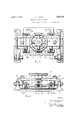
Figure 1 is a front elevational View of the lrnife blade adjusting means and support therefor l in'ure is a side elevational View of said lrni'fe adjusting: means;
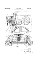
Figure 3 is a vertical. longitudinal, sectional view of the lmife adjusting means and a fragmentary portion of the tobacco cutting machine to which it is attached; and,
Figure i is a transverse sectional vi w of the knife adjusting means and the support therefor.
Referring to the drawings, the numeral indicates a feed drum mounted at the discharge end of a supporting; frame 6 of a tobacco cutting machine and located. above said drum and. properly journalcc in said fr are the presser rollers 7 and 8, rcspe .vuy. d rollers 7 and 8, respectively. are mounted and operated identically with 1927. Serial No. 185,515.
the construction illustrated in Patent No. 1,419,094.
In the front of the roller 8 is located a cross member 9 and beneath the latter and extending parallel thereto, in spaced rela tion therewith, is a co-acting cross member 10. These two cross members are arranged at a relatively spaced distance apart and are located at the discharge end of the frame and define a contracted throat through which tobacco is fed to the cutter. The mouth piece 9 is parallel to the roller 8 and it is set close to said roller in front thereof and extends downwardly as far as the bottom thereof. Each of the cross members 9 and 10, respectively, is provided on its outer face with removable ledger plates 11 and 12, respectively, across which ledger plates operates the cutter, the same consisting of a vertically, reciprocating, elongated cutting blade 18. The blade 18 has its bottom edge sharpened and is of such length as to correspond with the length of the mouth or discharge opening formed by the members 9 and 10, respectively.
From the member there extends a chute 1a onto which the cut fragments of tobacco drop for proper disposal.
The frame 6 of the machine is provided at its rear end with laterally spaced uprigl'its 15, on which are mounted vertical bars 16 forming slide Ways for a vertically reciprocatory cross-head 17 carrying the cutting blade 18. The inner edges of the bars 16 are under cut to retain the cross-head 17, and that portion of the cross-head, which engages the undercut portion of the bars 16, is provided with wear plates 19. The uprights are also provided with wear plates 20 to engage the opposing face of the crosshcad to compensate for wear in the sliding action of the cross-head thereon.
To the back of the cross-head 17 is bolted, or otherwise secured, a blade clamping plate 21, and this plate engages one face of the blade 18 and is held in firm contact with said blade thii'ougl'i the medium of stud bolts 22, which have one of their ends threaded as at- 23, and fastened to the opposite ends of said plate. The free ends of said bolts extend upwardly through fulcrum bars 2%, which are pivotally secured as at 25, to uprights 26 caradjusting wheel 28 mounted on abolt 29, the
free end of which bolt has a ball and socket connection with the cross-head 17., as at 30.
The upper ends of the bolts '22 have fitted thereon, nuts 31 having their inner faces spherical shaped, as at 32, so as to allow movement of said fulcrum members 24 upon operation of the wheel 28, in order to adjust said clamping plate toward and away from the blade 18. The adjusting of this plate naturally effects the adjustment of the blade 18 toward and away from the cross member 10 at the throat portion of the machine.
Mounted transversely of the front face of the cross-head 17 is an axle 33, which is mounted in brackets 3a carried by the said cross-head, and this axle 33 is provided between each of said brackets with adjusting bars 39 and each bar is provided with worms 35, which engage worms 36 mounted on standards 37 extending vertically through the cross-head 17 and have affixed on their upper ends adjusting wheels 38, and by rotation of the wheels 38 the bars 39 will in turn be rotated. The adjusting bars are supported'in such manner that they may engage the blade to flex the latter toward the ledger plates 11 and 12, of the cross members 9 and 10, respectively, thereby locating said blade in proper operative relation therewith.
The principal features inculcated in this improvement are r the provision of means whereby the blade may be held in fixed adjusted position and its cutting edge arranged in proper operative relation with the cross members by virtue of the wheels 28 and 38, respectively, without the necessity of stopping the operation or reciprocating action of the crosshead, which carries the blade.
It can be readily seen that by virtue of the wheel 28, levers 24 and bolts 22, that the blade 18 may be quickly and easily removed.
The operation of this improvement is identical with that embodied in Patent No. 1,419,094, and applicant lays no claim to the particular construction of this patent other than the improvements involved in the present application.
It is to be understood that certain minor changes may be resorted to without departing from the spirit and scope of the invention as claimed.
Having thus described my invention, what I claim as new is:
1. In atobacco cutting machine having a tobacco feeding means, the combination of a vertically reciprocatory cross-head, cross members located in said machine defining a tobacco outlet, a cutting blade associated with said cross-head, a clamping plate for said blade, bolts securing said. clamping plate to the cross-head for retaining said blade therein, fulcrum bars pivoted to the cross-head and embracing said bolts, and hand operated means for operating the fulcrum bars for controlling the movement of said clamping plate away from and toward the cross-head.
2. In combination with a tobacco cutting machine, having a feeding means, vertically spaced transverse members located in advance of the feed means and defining a. throat, a vertically reoiprocatory cross-head, means for operating said cross-head across the throat, a cutting blade carried by said cross-head, a clamping plate for said blade, means for adjustably securing said clamping plate to the cross-head for retaining said blade therein, said means comprising bolts slidably received in the cross-head and fulcrum bars pivotally securedfito the cross-head, said bolts having one end thereof secured to the clamping plate and the other end thereof secured intermediate the ends of the fulcrum bars, and manual means for operating the bars simultaneously.
In testimony whereof he hereunto affixes his signature.
LOUIS H. ZEUN.
Priority Applications (1)
| Application Number | Priority Date | Filing Date | Title |
|---|---|---|---|
| US18551527 US1852341A (en) | 1927-04-21 | 1927-04-21 | Tobacco cutting machine |
Applications Claiming Priority (1)
| Application Number | Priority Date | Filing Date | Title |
|---|---|---|---|
| US18551527 US1852341A (en) | 1927-04-21 | 1927-04-21 | Tobacco cutting machine |
Publications (1)
| Publication Number | Publication Date |
|---|---|
| US1852341A true US1852341A (en) | 1932-04-05 |
Family
ID=22681297
Family Applications (1)
| Application Number | Title | Priority Date | Filing Date |
|---|---|---|---|
| US18551527 Expired - Lifetime US1852341A (en) | 1927-04-21 | 1927-04-21 | Tobacco cutting machine |
Country Status (1)
| Country | Link |
|---|---|
| US (1) | US1852341A (en) |
-
1927
- 1927-04-21 US US18551527 patent/US1852341A/en not_active Expired - Lifetime
Similar Documents
| Publication | Publication Date | Title |
|---|---|---|
| US1515377A (en) | Stock cutter | |
| US32075A (en) | Alexander millar | |
| US2349034A (en) | Machine for making wood wool | |
| US1852341A (en) | Tobacco cutting machine | |
| US1372221A (en) | Reciprocating cutter for printing-presses | |
| US2254969A (en) | Combined cutter and scraper | |
| US1538066A (en) | Pulpwood-chipping machine | |
| US1603763A (en) | Feed mechanism | |
| US122602A (en) | Improvement in lozenge-machines | |
| US668343A (en) | Circular-gang-saw mill. | |
| US1464690A (en) | Wood chipper | |
| US546565A (en) | Tobacco-granulating machine | |
| US627882A (en) | Machine for pithing stalks. | |
| US2324950A (en) | Edge trimming means for use in rotary printing presses | |
| US1027320A (en) | Cotton-seed huller. | |
| US1657222A (en) | Gauge for sheet-cutting machines | |
| US939776A (en) | Pulverizer. | |
| US5672A (en) | Mark wilder | |
| US641791A (en) | Cardboard cutting and grooving device. | |
| US190180A (en) | Improvement in grain-reducing apparatus | |
| US793728A (en) | Machine for making metal binding-strips. | |
| US404130A (en) | Straw-cutter | |
| US266259A (en) | Machine for cutting the shafts or stems of feathers | |
| US327885A (en) | New yoek | |
| US933901A (en) | Fodder-cutter. |