US1852338A - Bridge construction - Google Patents
Bridge construction Download PDFInfo
- Publication number
- US1852338A US1852338A US220094A US22009427A US1852338A US 1852338 A US1852338 A US 1852338A US 220094 A US220094 A US 220094A US 22009427 A US22009427 A US 22009427A US 1852338 A US1852338 A US 1852338A
- Authority
- US
- United States
- Prior art keywords
- draw
- section
- unit
- units
- pontoon
- Prior art date
- Legal status (The legal status is an assumption and is not a legal conclusion. Google has not performed a legal analysis and makes no representation as to the accuracy of the status listed.)
- Expired - Lifetime
Links
Images
Classifications
-
- E—FIXED CONSTRUCTIONS
- E01—CONSTRUCTION OF ROADS, RAILWAYS, OR BRIDGES
- E01D—CONSTRUCTION OF BRIDGES, ELEVATED ROADWAYS OR VIADUCTS; ASSEMBLY OF BRIDGES
- E01D15/00—Movable or portable bridges; Floating bridges
- E01D15/14—Floating bridges, e.g. pontoon bridges
- E01D15/145—Floating bridges, e.g. pontoon bridges displaceable or with sections movable to allow passing of water-borne traffic
Definitions
- the invention is to provide a pontoon type of bridge, particularly adapted for use in bodies of tide water whlch may or may not become rough at times; one of the sectional or unit type wherein one or more units provide draw facilities to admit the passage through the bridge of the larger 1 vessels, and wherein one or more units provide passages for ships of relatively smaller sizes.
- the invention has also among its objects to provide a pontoon bridge structure which remains relatively steady in rough water and which is capable of supporting great loads, and the units of which are adapted for being maintained relatively level and in the same horizontal plane, irrespective of the rise or fall of the tide.
- a further object is to provide a pontoon bridge of the multiple unit type, which is adaptable for construction in any length, by the use of one or more of the desired individual unit structures and their interconnection in end to end relation, aliording pivotal movement between the same.
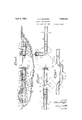
- FIG. 1 is a view in side elevation, illustrating one of the draw members swung to open position.
- Fig. 2 is a view in top plan of the structure illustrated in Fig. 1, showing more clearly the unit sections and the road and pedestrian ways.
- Fig. 3 is a view in top plan illustrating a longitudinally slidable unit draw section.
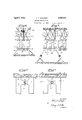
- Fig. 4 is a View in end elevation of one of preferably mounts a steadying weight 10 the units, particularly illustrating the buoyancy pontoons, the center balancing pontoon,
- Fig. 5 is a view in irregular section, through the structure, illustrated in Fig. 3.
- Fig. 6 is a View in detail section of the preferred connection between one of the draw units and its pier forming unit.
- Fig. 7 is a View in detail section of the" preferred connection between other unit sections.
- Each pontoon unit consists of a plurality l of column members 6, united by cross braces 5 7 and frame members 8.
- the lever portion or"? each column is surrounded by a pontoon cylinder 9, preferably of elongated construction. At its lower end each column.
- each column mounts a disk 11 of relatively large diameter.
- the weights 1O serve to submerge the pontoon cylinders preferably below the surface of the water body, and the disks 11, disposed at right angles to the column 6, counteract the action of the submerged wave currents, to maintain the unit structure relatively steady under a condition of rough water and render the same non-responsive to wave action.
- each unit When in use and in position, the respective units are held in position by any suitable type and number of anchors 12 resting r preferably on orsubmerged in the water ay bottom, the anchors being connected with the units through guy cables 13.
- One or more cylinders 14 of each unit may serve as co[inter-balancing or depth stabilizing cylinders for theyunit and each is provided i lar portions 19 and the pedestrian lanes 20.
- fixed approaches 21 and 22 are provided at opposite sides of the water way, the same jutting from the bank any desired distance.
- one end of the arch unit section 1 is pivotally connected to the outer end of the approach 21 by one or more horizontally aligned pivot connections 22, Fig. 7, with adjacent edges, of the tramway surface 18 thereof cut away as at 23, for reception of a filler plate 24 extending preferably the full width of the surface 18, thus allowing for a hinge movement of the section 1 relative to its approach 21.
- the arch unit section 1 is provided between the columns 25 with a passage 26 through which may pass relatively small ships of shallow draft, and the tramway surface 18 of this unit is arched as at 27 to clear its passage 26.
- Adjoining the arch unit section 1 and connected at one end therewith by the pivotal connections 22, Fig. 7, and with a filler 5 plate 2& disposed between the adjacent ends of the tramway surface is a relatively flat unit section 2, the same affording an abutment or pier section to which is connected 1 through one or more universal joint connections 28, Fig. 6, one end of a swinging draw section 3.
- Opposing the swinging draw section 3 is a complemental swinging draw unit 4 connected at one end, in alike manner, as is section 3, with one end of a fiat pier forming section 5, which is in turn connected with the approach 22.
- Any suitable means may be provided for swinging the draw sections 3 and 4 into and from open and closed position, the form illustrated consisting of submerged propellers 29 positioned in pairs at the free endof each draw section and simultaneously operated from any well known power source 30, connected with the propellers through power transmitting means 31.
- the swinging draw section 4 is connected ing of the parallel center disposed vehicu;
- this present pontoon bridge construction is capable of being maintained level or in a fixed plane, regardless of the rise or fall of the tide, by the filling .or emptying of the counterbalancing or depth stabilizing cylinders 14, also that the units are notsubject to the wave action, due to the positioning of the disks 11 near the bottom or lower edge of each unit and submerged to a considerable depth below the water way surface;
- propeller means has been illustrated and described as functioning to swing the draw sections, to and from open and closed position, it is to be understood that other suitable means, such as gear and pinion mechanism orcable mechanism may be employed.
- Fig. 3 is illustrateda modified form of draw unit which is adapted, when it is desired to open the same, to slide it longitudinally of its pier section 5, the means for accomplishing this operation being any of the well known types of mechanical structures, and it is not thought to be necessary to illustrate the same in detail in this present application.
- draw section 32 and the pier sections 5 are. provided with angular offset portions, so that the tramway surfaces 18 thereof may interconnect when the draw is in closed position.
- any suitable form of releasable lock mechanism may be employed to interlock the two draw sections together when the same are moved to aligned or draw closing position, and it will also be apparent that the propeller units 29 may be duplicated in the other pontoon sections for operation to act against a switch current and tend to maintain the units in alignment under extraordinary conditions.
- a floating bridge structure comprising a plurality of independent units arranged in end to end relation and each consisting of a plurality of vertically disposed pontoon structures, a counterbalancing weight at the lower end of each pontoon, a disk between each weightand the pontoon and disposed at right angles to the axis of the pontoon, aframe structure extending upwardly from the upper ends of the pontoons, means mounted on the frame whereby ballast material may be pumped selectively in and out of said pontoons, a tramway carried by the upper end of the frame structure, means for connecting the adjacent ends of said units for relative pivoting movement on a horizontal axis, one of said units mounted for pivotal movement in avertical axis relative to the other units to afl'ord a draw in said bridge structure, and means for anchoring the other units and means to propel the draw unit on its pivotal mounting.
Landscapes
- Engineering & Computer Science (AREA)
- Architecture (AREA)
- Civil Engineering (AREA)
- Structural Engineering (AREA)
- Bridges Or Land Bridges (AREA)
Description
April 5, 1932. c. F. SHAFFER BRIDGE CONSTRUCTION Filed Sept. 17. 1927 2 Sheets-Sheet I N V EN TOR. aw w A TTORNE Y.
April 5, 1932. c SHAFFER 1,852,338
BRIDGE CONSTRUCTION Filed Sept. 17. 1927 2 Sheets-Sheet 2 INVENTOR.
A TTORNE Y.
Patented Apr. 5, 1932 UNITED STATES PATENT OFFICE CLEVE F. SHAFFER, OF SAN FRANCISCO, CALIFORNIA BRIDGE CONSTRUCTION This invention relates to bridges and-more particularly to a pontoon type of bridge.
Among its objects, the invention is to provide a pontoon type of bridge, particularly adapted for use in bodies of tide water whlch may or may not become rough at times; one of the sectional or unit type wherein one or more units provide draw facilities to admit the passage through the bridge of the larger 1 vessels, and wherein one or more units provide passages for ships of relatively smaller sizes.
The invention has also among its objects to provide a pontoon bridge structure which remains relatively steady in rough water and which is capable of supporting great loads, and the units of which are adapted for being maintained relatively level and in the same horizontal plane, irrespective of the rise or fall of the tide.
A further object is to provide a pontoon bridge of the multiple unit type, which is adaptable for construction in any length, by the use of one or more of the desired individual unit structures and their interconnection in end to end relation, aliording pivotal movement between the same.
/Vith the above mentioned and other objects in view, the invention consists in the novel construction and combination of parts hereinafter described, illustrated in the accompanying drawings and pointed out in the claim hereto appended; it being understood that various changes in the form, proportion, size and minor details of construction within the scope of the claim may be resorted to without departing from the spirit or sacrificing any of the advantages of the invention.
In the drawings disclosing one embodiment of my invention- Fig. 1 is a view in side elevation, illustrating one of the draw members swung to open position.
Fig. 2 is a view in top plan of the structure illustrated in Fig. 1, showing more clearly the unit sections and the road and pedestrian ways.
Fig. 3 is a view in top plan illustrating a longitudinally slidable unit draw section.
Fig. 4 is a View in end elevation of one of preferably mounts a steadying weight 10 the units, particularly illustrating the buoyancy pontoons, the center balancing pontoon,
and the means to dampen the Wave action on the unit. y
Fig. 5 is a view in irregular section, through the structure, illustrated in Fig. 3.
Fig. 6 is a View in detail section of the preferred connection between one of the draw units and its pier forming unit.
Fig. 7 is a View in detail section of the" preferred connection between other unit sections.
In the drawings, wherein like characters of reference designate corresponding parts, the numerals 1, 2, 3, 4L and 5, indicate respectively, the arch, fiat, swinging draw, swinging draw and fiat portion units employed in the construction of the bridge illustrated, it being understood that the relative numberv and position of these units may vary, de-
pendent on the width of the water way to be bridged, the location of the channel and other conditions.
Each pontoon unit consists of a plurality l of column members 6, united by cross braces 5 7 and frame members 8. The lever portion or"? each column is surrounded by a pontoon cylinder 9, preferably of elongated construction. At its lower end each column.
and between the bottom of the cylinder and the weight each column mounts a disk 11 of relatively large diameter. The weights 1O serve to submerge the pontoon cylinders preferably below the surface of the water body, and the disks 11, disposed at right angles to the column 6, counteract the action of the submerged wave currents, to maintain the unit structure relatively steady under a condition of rough water and render the same non-responsive to wave action.
When in use and in position, the respective units are held in position by any suitable type and number of anchors 12 resting r preferably on orsubmerged in the water ay bottom, the anchors being connected with the units through guy cables 13. One or more cylinders 14 of each unit may serve as co[inter-balancing or depth stabilizing cylinders for theyunit and each is provided i lar portions 19 and the pedestrian lanes 20. In Figs. 1 and 2, fixed approaches 21 and 22 are provided at opposite sides of the water way, the same jutting from the bank any desired distance. i
As viewed from the left, Fig. 1 of the drawings, one end of the arch unit section 1 is pivotally connected to the outer end of the approach 21 by one or more horizontally aligned pivot connections 22, Fig. 7, with adjacent edges, of the tramway surface 18 thereof cut away as at 23, for reception of a filler plate 24 extending preferably the full width of the surface 18, thus allowing for a hinge movement of the section 1 relative to its approach 21. The arch unit section 1 is provided between the columns 25 with a passage 26 through which may pass relatively small ships of shallow draft, and the tramway surface 18 of this unit is arched as at 27 to clear its passage 26.
Adjoining the arch unit section 1 and connected at one end therewith by the pivotal connections 22, Fig. 7, and with a filler 5 plate 2& disposed between the adjacent ends of the tramway surface is a relatively flat unit section 2, the same affording an abutment or pier section to which is connected 1 through one or more universal joint connections 28, Fig. 6, one end of a swinging draw section 3. Opposing the swinging draw section 3 is a complemental swinging draw unit 4 connected at one end, in alike manner, as is section 3, with one end of a fiat pier forming section 5, which is in turn connected with the approach 22. The horizontal universal joint fulcrum connection between the swinging draw sections and the 1 relatively flat pier forming sections 2 and 0 5, afford a means whereby said swinging draw sections may be swung toaiford' a passage therebetween through which ships of a size,
and draft greater than that capable of passing; through the passage 26 may pass beyond 5 the bridge. 7
Any suitable means may be provided for swinging the draw sections 3 and 4 into and from open and closed position, the form illustrated consisting of submerged propellers 29 positioned in pairs at the free endof each draw section and simultaneously operated from any well known power source 30, connected with the propellers through power transmitting means 31.
The swinging draw section 4 is connected ing of the parallel center disposed vehicu;
to the end of the relatively fiat pier forming section 5 by the universal joint connection 28, Fig. 6, and the relatively fiat section 5 anchored by the members 12 and guy cables 13 is at its end connected with the approach 22, through the horizontal pivotal connection 22'--Fig. 7. It will be observed that this present pontoon bridge construction is capable of being maintained level or in a fixed plane, regardless of the rise or fall of the tide, by the filling .or emptying of the counterbalancing or depth stabilizing cylinders 14, also that the units are notsubject to the wave action, due to the positioning of the disks 11 near the bottom or lower edge of each unit and submerged to a considerable depth below the water way surface;
7 'While the propeller means has been illustrated and described as functioning to swing the draw sections, to and from open and closed position, it is to be understood that other suitable means, such as gear and pinion mechanism orcable mechanism may be employed.
In Fig. 3 is illustrateda modified form of draw unit which is adapted, when it is desired to open the same, to slide it longitudinally of its pier section 5, the means for accomplishing this operation being any of the well known types of mechanical structures, and it is not thought to be necessary to illustrate the same in detail in this present application.
In the structure illustrated in Fig. 3, the
draw section 32 and the pier sections 5 are. provided with angular offset portions, so that the tramway surfaces 18 thereof may interconnect when the draw is in closed position.
It is to be understood that any suitable form of releasable lock mechanism may be employed to interlock the two draw sections together when the same are moved to aligned or draw closing position, and it will also be apparent that the propeller units 29 may be duplicated in the other pontoon sections for operation to act against a switch current and tend to maintain the units in alignment under extraordinary conditions.
I claim v A floating bridge structure comprising a plurality of independent units arranged in end to end relation and each consisting of a plurality of vertically disposed pontoon structures, a counterbalancing weight at the lower end of each pontoon, a disk between each weightand the pontoon and disposed at right angles to the axis of the pontoon, aframe structure extending upwardly from the upper ends of the pontoons, means mounted on the frame whereby ballast material may be pumped selectively in and out of said pontoons, a tramway carried by the upper end of the frame structure, means for connecting the adjacent ends of said units for relative pivoting movement on a horizontal axis, one of said units mounted for pivotal movement in avertical axis relative to the other units to afl'ord a draw in said bridge structure, and means for anchoring the other units and means to propel the draw unit on its pivotal mounting.
In testimony whereof I have signed my name to this specification.
CLEVE F. SHAFFER.
Priority Applications (1)
| Application Number | Priority Date | Filing Date | Title |
|---|---|---|---|
| US220094A US1852338A (en) | 1927-09-17 | 1927-09-17 | Bridge construction |
Applications Claiming Priority (1)
| Application Number | Priority Date | Filing Date | Title |
|---|---|---|---|
| US220094A US1852338A (en) | 1927-09-17 | 1927-09-17 | Bridge construction |
Publications (1)
| Publication Number | Publication Date |
|---|---|
| US1852338A true US1852338A (en) | 1932-04-05 |
Family
ID=22822037
Family Applications (1)
| Application Number | Title | Priority Date | Filing Date |
|---|---|---|---|
| US220094A Expired - Lifetime US1852338A (en) | 1927-09-17 | 1927-09-17 | Bridge construction |
Country Status (1)
| Country | Link |
|---|---|
| US (1) | US1852338A (en) |
Cited By (10)
| Publication number | Priority date | Publication date | Assignee | Title |
|---|---|---|---|---|
| US2531484A (en) * | 1945-08-08 | 1950-11-28 | Frederick J Van Dusen | Device for swinging ships |
| US2856704A (en) * | 1954-05-28 | 1958-10-21 | Hebert Henry | Apparatus for cleaning the bottom of a body of water |
| US3849821A (en) * | 1971-04-02 | 1974-11-26 | Norconsult As | Submerged tunnel bridge |
| US6167582B1 (en) * | 1997-10-20 | 2001-01-02 | Man Technologies Ag | Floating bridge |
| US7048465B2 (en) * | 2000-07-05 | 2006-05-23 | Walters Kevin S | Method of routing and diverting traffic |
| WO2012033415A1 (en) | 2010-09-10 | 2012-03-15 | Lund, Mohr & Giæver-Enger Marin As | Construction of a floating bridge |
| CN103194959A (en) * | 2013-04-11 | 2013-07-10 | 重庆交通大学西南水运工程科学研究所 | Floating bridge adaptable to changing of riverway water level and capable of meeting requirements of riverway navigation |
| NO335058B1 (en) * | 2011-05-10 | 2014-09-01 | Lund Mohr & Giæver Enger Marin As | Device by a floating bridge structure. |
| NO338664B1 (en) * | 2010-09-10 | 2016-09-26 | Lund Mohr & Giæver Enger Marin As | Device at a floating bridge which is fixed at two attachment points by land in which the floating bridge is composed of a number of floating bridge elements. |
| NO20150509A1 (en) * | 2015-04-19 | 2016-10-20 | Roedstoel Oeystein | Floating bridge and platform built on anchored deep-flowing underwater foundation |
-
1927
- 1927-09-17 US US220094A patent/US1852338A/en not_active Expired - Lifetime
Cited By (15)
| Publication number | Priority date | Publication date | Assignee | Title |
|---|---|---|---|---|
| US2531484A (en) * | 1945-08-08 | 1950-11-28 | Frederick J Van Dusen | Device for swinging ships |
| US2856704A (en) * | 1954-05-28 | 1958-10-21 | Hebert Henry | Apparatus for cleaning the bottom of a body of water |
| US3849821A (en) * | 1971-04-02 | 1974-11-26 | Norconsult As | Submerged tunnel bridge |
| US6167582B1 (en) * | 1997-10-20 | 2001-01-02 | Man Technologies Ag | Floating bridge |
| US7048465B2 (en) * | 2000-07-05 | 2006-05-23 | Walters Kevin S | Method of routing and diverting traffic |
| NO338664B1 (en) * | 2010-09-10 | 2016-09-26 | Lund Mohr & Giæver Enger Marin As | Device at a floating bridge which is fixed at two attachment points by land in which the floating bridge is composed of a number of floating bridge elements. |
| WO2012033415A1 (en) | 2010-09-10 | 2012-03-15 | Lund, Mohr & Giæver-Enger Marin As | Construction of a floating bridge |
| CN103201432B (en) * | 2010-09-10 | 2016-11-16 | 蓬特玛尔公司 | The structure of pontoon bridge |
| CN103201432A (en) * | 2010-09-10 | 2013-07-10 | 隆德莫尔与贾埃弗-恩格马林公司 | Construction of a floating bridge |
| NO334941B1 (en) * | 2010-09-10 | 2014-07-28 | Lund Mohr & Giæver Enger Marin As | pontoon bridge |
| US8832891B2 (en) * | 2010-09-10 | 2014-09-16 | Lund, Mohr & Glever-Enger Marin As | Construction of a floating bridge |
| NO335058B1 (en) * | 2011-05-10 | 2014-09-01 | Lund Mohr & Giæver Enger Marin As | Device by a floating bridge structure. |
| CN103194959B (en) * | 2013-04-11 | 2015-11-18 | 重庆交通大学西南水运工程科学研究所 | A kind of can adapt to river course SEA LEVEL VARIATION and meet river course navigation demand pontoon bridge |
| CN103194959A (en) * | 2013-04-11 | 2013-07-10 | 重庆交通大学西南水运工程科学研究所 | Floating bridge adaptable to changing of riverway water level and capable of meeting requirements of riverway navigation |
| NO20150509A1 (en) * | 2015-04-19 | 2016-10-20 | Roedstoel Oeystein | Floating bridge and platform built on anchored deep-flowing underwater foundation |
Similar Documents
| Publication | Publication Date | Title |
|---|---|---|
| US1852338A (en) | Bridge construction | |
| NO159362B (en) | HALF SUBMITABLE FARTOEY. | |
| US3610193A (en) | Offshore drilling structure | |
| US3838657A (en) | Offshore moorings | |
| JP2011530040A (en) | A device that generates electricity from a fluid stream | |
| US1871475A (en) | Floating wharf | |
| US1264756A (en) | Floating breakwater. | |
| CN108360460B (en) | Sightseeing boat boarding device | |
| US3613622A (en) | Tiltable hydrofoil arrangement | |
| US2759331A (en) | Berthing pier | |
| US2550823A (en) | Dry dock | |
| US1367115A (en) | Floating and lifting bridge | |
| NO164725B (en) | Pontoon bridge. | |
| US3559606A (en) | Submersible barge roll control system | |
| KR102610707B1 (en) | Floating type bascule bridge | |
| US1750224A (en) | Floating harbor | |
| US1804667A (en) | Floating marine way | |
| US404488A (en) | johnson | |
| US1713457A (en) | Landing float | |
| US1996955A (en) | Floating wharf | |
| US1877994A (en) | Subaqueous tunnel | |
| RU2560738C1 (en) | Sea pontoon bridge | |
| US699231A (en) | Boat. | |
| US286374A (en) | Baumotte | |
| CN208455574U (en) | The underwater docking system of drag-line |