US1852336A - Electrical switch - Google Patents
Electrical switch Download PDFInfo
- Publication number
- US1852336A US1852336A US118328A US11832826A US1852336A US 1852336 A US1852336 A US 1852336A US 118328 A US118328 A US 118328A US 11832826 A US11832826 A US 11832826A US 1852336 A US1852336 A US 1852336A
- Authority
- US
- United States
- Prior art keywords
- contacts
- switch
- container
- circuit
- enclosure
- Prior art date
- Legal status (The legal status is an assumption and is not a legal conclusion. Google has not performed a legal analysis and makes no representation as to the accuracy of the status listed.)
- Expired - Lifetime
Links
- 239000012530 fluid Substances 0.000 description 17
- 239000007788 liquid Substances 0.000 description 13
- 239000004020 conductor Substances 0.000 description 12
- VZGDMQKNWNREIO-UHFFFAOYSA-N tetrachloromethane Chemical compound ClC(Cl)(Cl)Cl VZGDMQKNWNREIO-UHFFFAOYSA-N 0.000 description 10
- 230000006835 compression Effects 0.000 description 7
- 238000007906 compression Methods 0.000 description 7
- 238000010276 construction Methods 0.000 description 7
- 239000007789 gas Substances 0.000 description 5
- 239000012212 insulator Substances 0.000 description 4
- 230000002093 peripheral effect Effects 0.000 description 3
- 230000015572 biosynthetic process Effects 0.000 description 2
- 230000008020 evaporation Effects 0.000 description 2
- 238000001704 evaporation Methods 0.000 description 2
- 230000000717 retained effect Effects 0.000 description 2
- 208000036366 Sensation of pressure Diseases 0.000 description 1
- 230000000295 complement effect Effects 0.000 description 1
- 230000003247 decreasing effect Effects 0.000 description 1
- 238000004880 explosion Methods 0.000 description 1
- 239000002360 explosive Substances 0.000 description 1
- 238000010438 heat treatment Methods 0.000 description 1
- 238000007654 immersion Methods 0.000 description 1
- 229910000679 solder Inorganic materials 0.000 description 1
- 239000000126 substance Substances 0.000 description 1
- 210000003813 thumb Anatomy 0.000 description 1
Images
Classifications
-
- H—ELECTRICITY
- H01—ELECTRIC ELEMENTS
- H01H—ELECTRIC SWITCHES; RELAYS; SELECTORS; EMERGENCY PROTECTIVE DEVICES
- H01H33/00—High-tension or heavy-current switches with arc-extinguishing or arc-preventing means
- H01H33/60—Switches wherein the means for extinguishing or preventing the arc do not include separate means for obtaining or increasing flow of arc-extinguishing fluid
- H01H33/64—Switches wherein the means for extinguishing or preventing the arc do not include separate means for obtaining or increasing flow of arc-extinguishing fluid wherein the break is in gas
-
- H—ELECTRICITY
- H01—ELECTRIC ELEMENTS
- H01H—ELECTRIC SWITCHES; RELAYS; SELECTORS; EMERGENCY PROTECTIVE DEVICES
- H01H13/00—Switches having rectilinearly-movable operating part or parts adapted for pushing or pulling in one direction only, e.g. push-button switch
- H01H13/02—Details
- H01H13/04—Cases; Covers
- H01H13/06—Dustproof, splashproof, drip-proof, waterproof or flameproof casings
- H01H13/063—Casings hermetically closed by a diaphragm through which passes an actuating member
-
- H—ELECTRICITY
- H01—ELECTRIC ELEMENTS
- H01H—ELECTRIC SWITCHES; RELAYS; SELECTORS; EMERGENCY PROTECTIVE DEVICES
- H01H13/00—Switches having rectilinearly-movable operating part or parts adapted for pushing or pulling in one direction only, e.g. push-button switch
- H01H13/02—Details
- H01H13/04—Cases; Covers
- H01H13/06—Dustproof, splashproof, drip-proof, waterproof or flameproof casings
- H01H2013/066—Dustproof, splashproof, drip-proof, waterproof or flameproof casings using bellows
Definitions
- This invention relates' to electrical switches and more particularly to improved forms of enclosed electrical switches.
- the main object ofthe invention is to provide an electrical switch arrangement which is not only simple in construction and dependable and efficient in operation, but which also has improved safety features.
- Fig. 1 is a sectional elevational view illustrating one embodiment of the invention, taken on the line 1-1 of Fig. 2 g
- Fig. 2 is a plan view showing a group of switch units of the type shown in Fig. 1;
- Fig. 3 is a sectional view taken substantially along the line 3-3 of Fig. 1;
- Fig. l is a sectional elevational view illustrating another embodiment of the invention and Fig. 5 is also a sectional elevational view of still another form of construction incorporating features of the invention.
- a switchboard is illustrated at 10 formed with a switch supporting frame 11 which cooperates with a container portion 12 to form an enclosure for a cooperating pair of switch contacts as at 13 and 14 which are arranged to be bridged by a rotatable contact member 15.
- the container portion 12 may be secured upon and sealed in respect to the frame 11 in any suitable manner as by providing a peripheral flange 16 around the upper edge of the container portion 12, which flange engages a complementary flanged portion 17 formed on the frame 11.
- Suitable bolts as at 18 may be used to retain the container portion 12 in hermetically sealed relation to the frame 11,.
- the contacts 1?, and la respectively may be unipol-ted upon leading-in conductors 19 and 20. which are insulated from the frame 11 by suitable insulators 21 and 22. r[The insulators 21 and 22 may lre liernietically sealed within apertures as at Q3 and 24 formed in the frame 1926. Serial No. 118,328.
- the conductors 19 and 2O may also be hermetically sealed through the insulators.
- rlhe enclosure formed by the container portion 12, cooperating with the frame 11 acting as a cover therefor may be filled with suitable insulating fluid which may be either gaseous, or an arc-suppressing liquid partially filling the container with the remaining space filled with a readily compressible gas.
- suitable insulating fluid which may be either gaseous, or an arc-suppressing liquid partially filling the container with the remaining space filled with a readily compressible gas.
- the enclosure may be filled with air or if preferred, may be partially filled with an insulating liquid such as oil or fire extinguishing fluids, such as carbon tetrachloride.
- carbon tetrachloride or other volatile insulating liquids has been generally limited in electrical appara-tus to use in fuses wherein there are no moving parts extending to the exterior of the enclosure.
- actuating the contacts within the switch enclosure by the operation of actuating mechanism outside the container, the whole container, nevertheless, being hermetically sealed.
- the frame 11 is provided with a large aperture 25 through which the switch contact operating mechanism extends.
- a flexible or resilient,.deeply corrugated and substantially cylindrical metallic member 26 is provided.
- the member 26 at one end has its peripheral edges securely sealed as by solder to a ietaining ring 27 secured at the periphery of the aperture 25.
- a rigid end plate 28 is securely sealed in place as by the use of a peripheral ring 29 soldered or otherwise fixed to the member 26 and to the end plate.
- end plate 28 is operatively connected to the switch contact member 15 in a manner such that when the member 26 is compressed the circuit through the switch contacts will be closed. However, upon release of the member 26, the member 26 will be permitted to expand and the switch operating mechanism will be retracted to open circuit position.
- the rotatable contact bridging member 15 may be mounted upon a rotatable shaft 30 and insulated therefrom in any suitable manner as by a suitable insulating sleeve 31.
- the shaft 30 may be mounted within a suitable bearing 32 and formed atits upper end with a radially extending pin 33. Collars may be fixed upon the shaft 30'just above and below i the bearing 32, as shown, in order to fix the vertical position of the shaft.
- the upper end of the shaft may be loosely fitted within a sleeve member 34f"-formed with a spiral slot 35 for slidably receiving the pin 33.
- the sleeve member 34 may be formed with a yoke 36 suitably connected at 37 with a reciprocating rod 38 which is secured to the end plate 28. Vertical movements of the rod 38 will accordingly result, by reason of the spiral slot and pin connection, in rotational operation of the Contact 15.
- suitable switch operating mechanism including an operating lever 39 pivotally mounted at 40 upon the rear of the switchboard 10 and operatively connected through link 41, bell crank levers 42 and 43 and link 44 to the end plate 28.
- the bell crank levers 42 and 43 may be secured upon a. shaft 45 which may be common to a plurality or group of switch units as shown in Fig. 2.
- the single operating handle 39 may be used to control, for example, the three switch units for opening and closing the three conductors of a three phase circuit.
- the upper or free end of the compressible member 26 may be restrained against sidewise movement by vertically extending guide rods as at 46 and 47, which slidably engage apertures through the end plate member 28.
- the operating lever 39 is retained in the closed circuit position and may be locked in such position by any Well known form of remotely controlled magnetic trip device as indicated at 48, which also, if desired, may be arranged to be tripped manually in a conventional manner by pressing a'thumb button 49.
- the switch enclosure here shown is partially filled with a body of insulating fluid 50 such as carbon tetrachloride which immerses the switch contacts.
- the remainder of the enclosure is filled with a readily compressible fluid such as air, or carbon tetra chloride vapor, either at atmospheric pres sure or, if desired under special circumstances, Y at a higher or lower pressure. Therefore, when the switch is moved to closed circuit position, the member 26 will be compressed and the volume of fluid therein will be decreased, thus building up a substantial potential force within the switch tending to open the same. Accordingly, when either the manual or automatic trip devices are operated, the pressure of the entrapped fluid within the enclosure supplemented by the resiliency of the member 2G will cause the switch operating parts to quickly jump to their open circuit positions. Thus a quick break at the contacts is insured.
- the sudden increase in pressure resulting from the formation of or expansion of gases due to arcing at the first inoments of the circuit breaking action are utilized to good advantave to hasten the expansion of the container. bPositive and quick circuit breaking action is thus insured even though heavy currents are broken.
- the switch in its preferred form being hermetically sealed is available for the control 'of electric power, lighting or heating circuits in regions where inflammable or explosive media prevails as in chemical plants, oil refineries, garages, etc., where the arc produced by the opening or closing of the switch must be covered to avoid danger of fire or explosion.
- the switch is also well adapted for use where the light produced by the arcing at the switch contacts, ifnot covered, would damage the products being manufactured at the establishnient, such as in the photographic industry.
- FIG. 4 another embodiment of the invention is illustrated.
- a frame 51 is provided which also comprises a conductor for one side of the electric circuit, a line wire 52 being secured thereto.
- a pair of cooperating switch contacts 53 and 54 are provided and are enclosed within a collapsible drum' 55, which if desired may be constructed in a manner similar to the compressible member 26 above described.
- the lower end of the drum 55 is hermetically sealed at 56 to the base of the frame 51 while the upper or free end of the drum is closed ofi' and hermetically sealed by an end plate member 57.
- the contact 54 is supported and electrically connected to the end plate 57' by a support member 58.
- the contact 53 is provided with a supporting and leading-in conductor l59 passing through a sealed-in insulating sleeve 60 which extends to the exterior of the drum. Externally ot the drum the supporting conductor 59 is connected to a line wire 61.
- To operate the switch it is merely necessary to raise or lower the end plate 57, thereby compressing or releasing the drum and bringing the contacts 53 and 54 into or out of engagement.
- ylthis if desired may be readily accomplished by a simple toggle mechanism comprising a bell crank lever 62 pivotally connected to a link 63 which in turn is pivotally attached to the end plate 57.
- the bell crank member 62 may be pivotally mounted at 64 upon the frame 51.
- the switch With the parts as shown the switch is in closed position and is held in this condition by the toggle mechanism, the bell crank 62 being .lodged in an over center position and held in such position by a stop member 65.
- the toggle locking mechanism On raising the handle of the bell crank mem'- ber the toggle locking mechanism may be released whereupon the compressible drum is permitted to expand, separating the contacts with a quick breaking action, which interrupts the circuit therethrough without c3;- cessive arcing'.
- a wall bracket 66 is provided which also forms the base portion of a switch enclosure, the wall portions of which comprise a compressible drum member 67 of the general type above described.
- the ⁇ drum 67 may be hermetically sealed at 68 to the bracket or frame member 66.
- Line wires 69 and 70 respectively are attached to the leading-in conductors 71 and 72 which extend through insulators78 and 7 4 and terminate at contacts 7 5 and 76 within the enclosure.
- flhe insulators 7 3 and 74 may be hermetically sealed both to the leading-in conductors and to the wall bracket at the apertures where they pass through the bracket.
- a rigid end vplate 77 may be hermetically lsealed in place.
- This end plate carries a supporting member 78 upon which a Contact bridging member 79 is mounted.
- the upper end of the compressible drum may be restrained against sidewise movement by means of guide rods 80 and 81 having their lower ends secured in the wall bracket 66 and their upper ends secured in another wall bracket 82.
- Apertured lugs at 83 may be provided upon the end plate 77 for slidably engaging the guide rods.
- the up and down movement of the end plate 77 may be limited if desired by stop members 84 and 85 adj ustably secured to the guide rods A80 and 81.
- a suitable lever 8 6 may be provided and operatively connected to the end plate 77 by an arrangement of levers and links including links 87 and 89 pivoted to link 91 at 92, the other end of link 91 being pivoted to the trame at 93.
- a bell crank lever 90 suitably connects link 89 with link 88 which in turn is connected to the head 77 as will be yreadily understood from the drawings.
- An electric switch comprising cooperating contacts, an hermetically sealed container for said contacts, an arc-suppressing volatile liquid immersing said contacts and partially filling the container, the remaining space therein being filled with a readily compressible Huid, a portion of said container comprising a flexible corrugated substantially cylindrical and compressible wall member, a l
- An electric. switch comprising cooperating contacts within a container, an insulating liquid immersing said contacts and partially filling the container, the remaining space therein being filled with a readily compressible fluid, a portion ot said container comprising a flexible corrugated and compressible wall member having its exterior eX- posed to the atmosphere, a reciprocating contact operating member secured in respect to the free end of said flexible portion within the container whereby when said wall member is compressed said contacts will be retained in one position, switch operating linkage secured externally to said flexible portion and retaining said wall portion under compression, said compressed flexible portion and the fluid pressure therein serving upon actuation otu said operating mechanism to quickly move the switch parts to their opposite position.
- fin electric switch comprising cooperating contacts, an hermetically sealed container surrounding said contacts, at least one insulated leading-in conductor passing through the container walls for said contacts, an arcsuppressing liquid immersing said contacts and partially filling the container, the remaining space therein being filled with a readily compressible fluid, an extension to said container having a. compressible wall member, a reciprocating contact operating member secured to said extension within the container, whereby when said wall member is compressed the circuit through said contacts will be closed, switch operating mechanism secured externally to said extension and retaining said wall portion under compression when the circuit is closed, said compressed extension and the fluid pressure therein serving upon actuation of said operating mechanism to quickly move the switch parts to open circuit position'thereby providing a quick break at said contacts.
- An electric switch comprising cooperating contacts, an hermetically sealed container surrounding said contacts, insulated leadingin conductors passing through the container walls for said contacts, an insulating liquid immersing said contacts and partially filling the container, the remaining space therein being filled with a readily compressible iiuid, an extension to said container having a compressible wall member and a rigid end plate member, a reciprocating contact operating member secured to said end plate within the container, and a rotatable Contact bridging member having a spiral slot and pin connection with said reciprocating member ible corrugated wall member, a contact operatiL-g member secured in respect to the freeexcellent end of said iexible portion within the container whereby when said wall member is compressed the circuit through said contacts will be closed, switch operating mechanism secured externally to said flexible portion and retaining said wall portion under compression when the circuit is closed, quickreleasable retaining means for said mechanism, said compressed flexible portion and the fluid pressure therein serving upon release of said retaining means to quickly move the switch parts to open circuit position thereby providing
- G. in electric switch comprising cooperating contacts, a sealed container surrounding said contacts, arc-suppressing fluid immersing said contacts, a portion of said container comprising a flexible corrugated compressible wall member, a contact operating member secured in respect to the free end of said flexible portion within the container, whereby when said wall member is compressed the circuit through said contacts will be closed, switch operating mechanism secured externally to said flexible portion and retaining said wall portion under compression when the circuit is closed, quick-releasable tripping means Jfor said operating mechanism, said compressed extension and the duid pressure therein serving upon actuation of said tripping means to quickly move the switch parts to open circuit position thereby providing a quick break at said contacts.
- An electric switch comprising cooperating contacts, a container surrounding said contacts, a portion of said container comprising a flexible compressible wall member,-a contact operating member secured in respect 'to said flexible portion within the container whereby when said wall member is compressed the circuit 'through said contacts will be closed, switch operating mechanism secured externally to said flexible portion and retaining said wall portion under compression when the circuit is closed, quick-releasable tripping means for said operating mechanism, said compressed extension and the fluid pressure therein serving upon actuation of said tripping means to quickly move the switch parts to open circuit position thereby providing a quick break at said contacts.
- An electric switch comprising cooperating contacts, an hermetically sealed container surrounding said contacts, insulated leadingin conductors passing through the container walls for said contacts, an arc-suppressing volatile liquid immersing said contacts and partially filling the container, the remaining space therein being filled with a readily coinnressible fluid.
- an extension to said container having a resilient corrugated substantially cylindrical and compressible wall member and a rigid end plate member, a reciprocating Contact operating member secured to said Lacasse ,end plate within the container, contacts operated by said reciprocating member whereby when said Wall member lis compressed the circuit through said contacts Will'be closed, switch operating mechanism.
- An electric switch comprising cooperating contacts, an hermetically sealed container surrounding said contacts, insulated leadingin conductors passing through the container walls for sald contacts, an arcsuppress1ng volatile liquid immersing said contacts and partially filling the container, the remaining space therein being lilled with a readily compressible iuid, an extension to said container having a ilexible corrugated substantially cylindrical'and compressible wall member and a rigid end plate member, a reciprocatin contact operating member secured to said en plate Within the container, a rotatable contact bridging member having a spiral slot and pin connection with said reciprocating member whereby when said Wall member is compressed the circuit through said contacts will,
- a quick-break electrical switch construction having contacts for making and breaking a circuit carrying heavy current or a high potential and having a sealed enclosure surrounding the contacts, said contacts being fixedrespectively to relatively movable wall portions of said enclosure and being immersed in a volatile insulating liquid, the enclosure being of such dimensions and the liquid being suiiiciently volatile to substantially hasten the expansion of the enclosure upon formation of heavy currentarcs at the first momentsv of the circuit breaking action.
- An electrical switch construction having contacts for making and breaking a circuit carrying heavy current or ahigh potential and having a sealed enclosure surrounding the contacts, said enclosure having a portion which is freely expansible upon breaking the circuit at the contacts, to accommodate the increasedvolumeot ⁇ gases therein, means operatively connecting one of said contacts with said expansible portion, and external means for operating the expansible portion.
Landscapes
- Circuit Breakers (AREA)
Description
April 5, 1932- M. M, SAMUELS ET Al. 1,852,336
ELECTRICAL SWITCH Filed June 24, 1926 5141)@446065 TOM/16 5005K Patented Apr. 5, 1932 UNITED STATES PATENT OFFICE MAURICE M. SAMUELS, 0F NEW YORK, AND TOMAS '.BOCEK, OF BROOKLYN, NEW YORK ELECTRICAL SWITCH Application filed June 24,
This invention relates' to electrical switches and more particularly to improved forms of enclosed electrical switches.
The main object ofthe invention is to provide an electrical switch arrangement which is not only simple in construction and dependable and efficient in operation, but which also has improved safety features.
Further and more specific objects, features and advantages will more clearly appear from the detailed description given below taken in connection with the accompanying drawings which form a part of this specification.
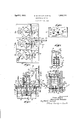
ln the drawings Fig. 1 is a sectional elevational view illustrating one embodiment of the invention, taken on the line 1-1 of Fig. 2 g
Fig. 2 is a plan view showing a group of switch units of the type shown in Fig. 1;
Fig. 3 is a sectional view taken substantially along the line 3-3 of Fig. 1;
Fig. l is a sectional elevational view illustrating another embodiment of the invention and Fig. 5 is also a sectional elevational view of still another form of construction incorporating features of the invention.
Referring to the construction as shown in Fig. 1, a switchboard is illustrated at 10 formed with a switch supporting frame 11 which cooperates with a container portion 12 to form an enclosure for a cooperating pair of switch contacts as at 13 and 14 which are arranged to be bridged by a rotatable contact member 15. The container portion 12 may be secured upon and sealed in respect to the frame 11 in any suitable manner as by providing a peripheral flange 16 around the upper edge of the container portion 12, which flange engages a complementary flanged portion 17 formed on the frame 11. Suitable bolts as at 18 may be used to retain the container portion 12 in hermetically sealed relation to the frame 11,.
The contacts 1?, and la respectively may be unipol-ted upon leading-in conductors 19 and 20. which are insulated from the frame 11 by suitable insulators 21 and 22. r[The insulators 21 and 22 may lre liernietically sealed within apertures as at Q3 and 24 formed in the frame 1926. Serial No. 118,328.
11. The conductors 19 and 2O may also be hermetically sealed through the insulators.
rlhe enclosure formed by the container portion 12, cooperating with the frame 11 acting as a cover therefor, may be filled with suitable insulating fluid which may be either gaseous, or an arc-suppressing liquid partially filling the container with the remaining space filled with a readily compressible gas. F or example, the enclosure may be filled with air or if preferred, may be partially filled with an insulating liquid such as oil or fire extinguishing fluids, such as carbon tetrachloride. Heretofore the use of carbon tetrachloride or other volatile insulating liquids has been generally limited in electrical appara-tus to use in fuses wherein there are no moving parts extending to the exterior of the enclosure. lin order to prevent rapid evaporation of the volatile liquid, it is desirable to provide an hermetically sealed container, but in switch constructions this has heretofore been difficult inasmuch as moving parts of the switch operating mechanism usually extend from the contacts within the container to points externally of the container. The difficulties of providing a permanent hermetical seal at the point where these moving parts pass through the container wall has heretofore inhibited the general use of desirable but volatile fire extinguishing fluids such as carbon tetrachloride, for the immersion of electrical switch contacts.
According to the presentinvention, means are provided for actuating the contacts within the switch enclosure by the operation of actuating mechanism outside the container, the whole container, nevertheless, being hermetically sealed. Referring to Fig. 1, the frame 11 is provided with a large aperture 25 through which the switch contact operating mechanism extends. To hermetically seal this aperture, however, a flexible or resilient,.deeply corrugated and substantially cylindrical metallic member 26 is provided. The member 26 at one end has its peripheral edges securely sealed as by solder to a ietaining ring 27 secured at the periphery of the aperture 25. At the other or free end of the member 26 a rigid end plate 28 is securely sealed in place as by the use of a peripheral ring 29 soldered or otherwise fixed to the member 26 and to the end plate. Internally of the enclosure the end plate 28 is operatively connected to the switch contact member 15 in a manner such that when the member 26 is compressed the circuit through the switch contacts will be closed. However, upon release of the member 26, the member 26 will be permitted to expand and the switch operating mechanism will be retracted to open circuit position.
One form of switch operating mechanism as shown in Fig. 1 will now be described. The rotatable contact bridging member 15 may be mounted upon a rotatable shaft 30 and insulated therefrom in any suitable manner as by a suitable insulating sleeve 31. The shaft 30 may be mounted within a suitable bearing 32 and formed atits upper end with a radially extending pin 33. Collars may be fixed upon the shaft 30'just above and below i the bearing 32, as shown, in order to fix the vertical position of the shaft. The upper end of the shaft may be loosely fitted within a sleeve member 34f"-formed with a spiral slot 35 for slidably receiving the pin 33. The sleeve member 34 may be formed with a yoke 36 suitably connected at 37 with a reciprocating rod 38 which is secured to the end plate 28. Vertical movements of the rod 38 will accordingly result, by reason of the spiral slot and pin connection, in rotational operation of the Contact 15.
Externally of the enclosure suitable switch operating mechanism may be provided including an operating lever 39 pivotally mounted at 40 upon the rear of the switchboard 10 and operatively connected through link 41, bell crank levers 42 and 43 and link 44 to the end plate 28. The bell crank levers 42 and 43 may be secured upon a. shaft 45 which may be common to a plurality or group of switch units as shown in Fig. 2. In this arrangement the single operating handle 39 may be used to control, for example, the three switch units for opening and closing the three conductors of a three phase circuit.
By referring to Fig. 2 it will be noted that the upper or free end of the compressible member 26 may be restrained against sidewise movement by vertically extending guide rods as at 46 and 47, which slidably engage apertures through the end plate member 28.
In the position shown in the drawings, the operating lever 39 is retained in the closed circuit position and may be locked in such position by any Well known form of remotely controlled magnetic trip device as indicated at 48, which also, if desired, may be arranged to be tripped manually in a conventional manner by pressing a'thumb button 49.
The switch enclosure here shown is partially filled with a body of insulating fluid 50 such as carbon tetrachloride which immerses the switch contacts. The remainder of the enclosure is filled with a readily compressible fluid such as air, or carbon tetra chloride vapor, either at atmospheric pres sure or, if desired under special circumstances, Y at a higher or lower pressure. Therefore, when the switch is moved to closed circuit position, the member 26 will be compressed and the volume of fluid therein will be decreased, thus building up a substantial potential force within the switch tending to open the same. Accordingly, when either the manual or automatic trip devices are operated, the pressure of the entrapped fluid within the enclosure supplemented by the resiliency of the member 2G will cause the switch operating parts to quickly jump to their open circuit positions. Thus a quick break at the contacts is insured. The quick break inade possible by this ar rangement and also the possibility of using highly efficient arc-suppressing liquids, even though volatile, renders it possible to use this switch for breaking short circuit currents of great magnitude.
IVhen an electric circuit is automatically interrupted, with over-current or over-voltage conditions, if the circuit breaking contacts are in oil or other mediums, gases are often formed in sufficient quantity and of such character that the vessel containing the oil or other insulating medium is caused to explode unless provided with a large opening to the atmosphere. Such large opening also, of course, permits the insulating mediumpto escape by evaporation or capillary action. However, with the present inven tion the enclosure being formed with an expansible portion is able to readily accommodate sudden vincreases in volume of gases therein without danger of the enclosure being ruptured. In fact, according to our invention the sudden increase in pressure resulting from the formation of or expansion of gases due to arcing at the first inoments of the circuit breaking action, are utilized to good advantave to hasten the expansion of the container. bPositive and quick circuit breaking action is thus insured even though heavy currents are broken. Also, the switch in its preferred form being hermetically sealed, is available for the control 'of electric power, lighting or heating circuits in regions where inflammable or explosive media prevails as in chemical plants, oil refineries, garages, etc., where the arc produced by the opening or closing of the switch must be covered to avoid danger of fire or explosion. The switch is also well adapted for use where the light produced by the arcing at the switch contacts, ifnot covered, would damage the products being manufactured at the establishnient, such as in the photographic industry.
In Fig. 4 another embodiment of the invention is illustrated. Here a desirable construction is provided for small enclosed switches which may be operated directly and manually. A frame 51 is provided which also comprises a conductor for one side of the electric circuit, a line wire 52 being secured thereto. A pair of cooperating switch contacts 53 and 54 are provided and are enclosed within a collapsible drum' 55, which if desired may be constructed in a manner similar to the compressible member 26 above described. The lower end of the drum 55 is hermetically sealed at 56 to the base of the frame 51 while the upper or free end of the drum is closed ofi' and hermetically sealed by an end plate member 57. The contact 54 is supported and electrically connected to the end plate 57' by a support member 58. The contact 53 is provided with a supporting and leading-in conductor l59 passing through a sealed-in insulating sleeve 60 which extends to the exterior of the drum. Externally ot the drum the supporting conductor 59 is connected to a line wire 61. To operate the switch it is merely necessary to raise or lower the end plate 57, thereby compressing or releasing the drum and bringing the contacts 53 and 54 into or out of engagement. ylthis if desired may be readily accomplished by a simple toggle mechanism comprising a bell crank lever 62 pivotally connected to a link 63 which in turn is pivotally attached to the end plate 57. The bell crank member 62 may be pivotally mounted at 64 upon the frame 51. With the parts as shown the switch is in closed position and is held in this condition by the toggle mechanism, the bell crank 62 being .lodged in an over center position and held in such position by a stop member 65. On raising the handle of the bell crank mem'- ber the toggle locking mechanism may be released whereupon the compressible drum is permitted to expand, separating the contacts with a quick breaking action, which interrupts the circuit therethrough without c3;- cessive arcing'.
Referring to Fig. 5, a further embodiment of the invention is illustrated. A wall bracket 66 is provided which also forms the base portion of a switch enclosure, the wall portions of which comprise a compressible drum member 67 of the general type above described. The` drum 67 may be hermetically sealed at 68 to the bracket or frame member 66. Line wires 69 and 70 respectively are attached to the leading-in conductors 71 and 72 which extend through insulators78 and 7 4 and terminate at contacts 7 5 and 76 within the enclosure. flhe insulators 7 3 and 74 may be hermetically sealed both to the leading-in conductors and to the wall bracket at the apertures where they pass through the bracket. At the upper end of the compressibley drum a rigid end vplate 77 may be hermetically lsealed in place. This end plate carries a supporting member 78 upon which a Contact bridging member 79 is mounted. The upper end of the compressible drum may be restrained against sidewise movement by means of guide rods 80 and 81 having their lower ends secured in the wall bracket 66 and their upper ends secured in another wall bracket 82. Apertured lugs at 83 may be provided upon the end plate 77 for slidably engaging the guide rods. The up and down movement of the end plate 77 may be limited if desired by stop members 84 and 85 adj ustably secured to the guide rods A80 and 81. For operating the switch a suitable lever 8 6 may be provided and operatively connected to the end plate 77 by an arrangement of levers and links including links 87 and 89 pivoted to link 91 at 92, the other end of link 91 being pivoted to the trame at 93. A bell crank lever 90 suitably connects link 89 with link 88 which in turn is connected to the head 77 as will be yreadily understood from the drawings.
What we claim as new and desire to secure by Letters Patent of the United States is:
1. An electric switch comprising cooperating contacts, an hermetically sealed container for said contacts, an arc-suppressing volatile liquid immersing said contacts and partially filling the container, the remaining space therein being filled with a readily compressible Huid, a portion of said container comprising a flexible corrugated substantially cylindrical and compressible wall member, a l
reciprocating contact operating member sccured in respect to the tree end of said flexible portion within the container, whereby when said wall member is compressed the circuit through said contacts will be closed. switch actuating mechanism secured externally to said iexible portion and retaining said wall portion under compression when the circuit is closed, said compressed flexible portion and the fluid pressure therein serving upon actuation of said operating mechanism to quickly move the switch parts to open circuit position thereby providing a quick break at said contacts. Y
2. An electric. switch comprising cooperating contacts within a container, an insulating liquid immersing said contacts and partially filling the container, the remaining space therein being filled with a readily compressible fluid, a portion ot said container comprising a flexible corrugated and compressible wall member having its exterior eX- posed to the atmosphere, a reciprocating contact operating member secured in respect to the free end of said flexible portion within the container whereby when said wall member is compressed said contacts will be retained in one position, switch operating linkage secured externally to said flexible portion and retaining said wall portion under compression, said compressed flexible portion and the fluid pressure therein serving upon actuation otu said operating mechanism to quickly move the switch parts to their opposite position.
3. fin electric switch comprising cooperating contacts, an hermetically sealed container surrounding said contacts, at least one insulated leading-in conductor passing through the container walls for said contacts, an arcsuppressing liquid immersing said contacts and partially filling the container, the remaining space therein being filled with a readily compressible fluid, an extension to said container having a. compressible wall member, a reciprocating contact operating member secured to said extension within the container, whereby when said wall member is compressed the circuit through said contacts will be closed, switch operating mechanism secured externally to said extension and retaining said wall portion under compression when the circuit is closed, said compressed extension and the fluid pressure therein serving upon actuation of said operating mechanism to quickly move the switch parts to open circuit position'thereby providing a quick break at said contacts.
4. An electric switch comprising cooperating contacts, an hermetically sealed container surrounding said contacts, insulated leadingin conductors passing through the container walls for said contacts, an insulating liquid immersing said contacts and partially filling the container, the remaining space therein being filled with a readily compressible iiuid, an extension to said container having a compressible wall member and a rigid end plate member, a reciprocating contact operating member secured to said end plate within the container, and a rotatable Contact bridging member having a spiral slot and pin connection with said reciprocating member ible corrugated wall member, a contact operatiL-g member secured in respect to the free terrasse end of said iexible portion within the container whereby when said wall member is compressed the circuit through said contacts will be closed, switch operating mechanism secured externally to said flexible portion and retaining said wall portion under compression when the circuit is closed, quickreleasable retaining means for said mechanism, said compressed flexible portion and the fluid pressure therein serving upon release of said retaining means to quickly move the switch parts to open circuit position thereby providing a quick break at said contacts.
G. in electric switch comprising cooperating contacts, a sealed container surrounding said contacts, arc-suppressing fluid immersing said contacts, a portion of said container comprising a flexible corrugated compressible wall member, a contact operating member secured in respect to the free end of said flexible portion within the container, whereby when said wall member is compressed the circuit through said contacts will be closed, switch operating mechanism secured externally to said flexible portion and retaining said wall portion under compression when the circuit is closed, quick-releasable tripping means Jfor said operating mechanism, said compressed extension and the duid pressure therein serving upon actuation of said tripping means to quickly move the switch parts to open circuit position thereby providing a quick break at said contacts.
7. An electric switch comprising cooperating contacts, a container surrounding said contacts, a portion of said container comprising a flexible compressible wall member,-a contact operating member secured in respect 'to said flexible portion within the container whereby when said wall member is compressed the circuit 'through said contacts will be closed, switch operating mechanism secured externally to said flexible portion and retaining said wall portion under compression when the circuit is closed, quick-releasable tripping means for said operating mechanism, said compressed extension and the fluid pressure therein serving upon actuation of said tripping means to quickly move the switch parts to open circuit position thereby providing a quick break at said contacts.
8. An electric switch comprising cooperating contacts, an hermetically sealed container surrounding said contacts, insulated leadingin conductors passing through the container walls for said contacts, an arc-suppressing volatile liquid immersing said contacts and partially filling the container, the remaining space therein being filled with a readily coinnressible fluid. an extension to said container having a resilient corrugated substantially cylindrical and compressible wall member and a rigid end plate member, a reciprocating Contact operating member secured to said Lacasse ,end plate within the container, contacts operated by said reciprocating member whereby when said Wall member lis compressed the circuit through said contacts Will'be closed, switch operating mechanism. secured externally to said end plate and retaining said wall portion under compression when the circuit is closed, quick releasing tripping means for said operating mechanism, said compressed extension and the fluid pressure therein serving upon actuation of said magnetic means to quickly move the switch parts to open circuit position thereby providing a quick break at said contacts. A. l
9. An electric switch comprising cooperating contacts, an hermetically sealed container surrounding said contacts, insulated leadingin conductors passing through the container walls for sald contacts, an arcsuppress1ng volatile liquid immersing said contacts and partially filling the container, the remaining space therein being lilled with a readily compressible iuid, an extension to said container having a ilexible corrugated substantially cylindrical'and compressible wall member and a rigid end plate member, a reciprocatin contact operating member secured to said en plate Within the container, a rotatable contact bridging member having a spiral slot and pin connection with said reciprocating member whereby when said Wall member is compressed the circuit through said contacts will,
l be closed, and vwhen said wall member is re'- leased the circuit through said contacts will be opened.
10. A quick-break electrical switch construction having contacts for making and breaking a circuit carrying heavy current or a high potential and having a sealed enclosure surrounding the contacts, said contacts being fixedrespectively to relatively movable wall portions of said enclosure and being immersed in a volatile insulating liquid, the enclosure being of such dimensions and the liquid being suiiiciently volatile to substantially hasten the expansion of the enclosure upon formation of heavy currentarcs at the first momentsv of the circuit breaking action.
11. An electrical switch construction having contacts for making and breaking a circuit carrying heavy current or ahigh potential and having a sealed enclosure surrounding the contacts, said enclosure having a portion which is freely expansible upon breaking the circuit at the contacts, to accommodate the increasedvolumeot` gases therein, means operatively connecting one of said contacts with said expansible portion, and external means for operating the expansible portion.
In testimony whereof we have signed `our names tothis s eciication.
URICE M. SAMUELS. lTOMAS BOCEK.
Priority Applications (1)
| Application Number | Priority Date | Filing Date | Title |
|---|---|---|---|
| US118328A US1852336A (en) | 1926-06-24 | 1926-06-24 | Electrical switch |
Applications Claiming Priority (1)
| Application Number | Priority Date | Filing Date | Title |
|---|---|---|---|
| US118328A US1852336A (en) | 1926-06-24 | 1926-06-24 | Electrical switch |
Publications (1)
| Publication Number | Publication Date |
|---|---|
| US1852336A true US1852336A (en) | 1932-04-05 |
Family
ID=22377897
Family Applications (1)
| Application Number | Title | Priority Date | Filing Date |
|---|---|---|---|
| US118328A Expired - Lifetime US1852336A (en) | 1926-06-24 | 1926-06-24 | Electrical switch |
Country Status (1)
| Country | Link |
|---|---|
| US (1) | US1852336A (en) |
Cited By (2)
| Publication number | Priority date | Publication date | Assignee | Title |
|---|---|---|---|---|
| US3187120A (en) * | 1962-10-08 | 1965-06-01 | Burroughs Corp | Multi-contact manually-operated electric switch with lever actuating means |
| DE1286179B (en) * | 1964-01-14 | 1969-01-02 | Bbc Brown Boveri & Cie | Electric switch |
-
1926
- 1926-06-24 US US118328A patent/US1852336A/en not_active Expired - Lifetime
Cited By (2)
| Publication number | Priority date | Publication date | Assignee | Title |
|---|---|---|---|---|
| US3187120A (en) * | 1962-10-08 | 1965-06-01 | Burroughs Corp | Multi-contact manually-operated electric switch with lever actuating means |
| DE1286179B (en) * | 1964-01-14 | 1969-01-02 | Bbc Brown Boveri & Cie | Electric switch |
Similar Documents
| Publication | Publication Date | Title |
|---|---|---|
| US3542986A (en) | Quick-make,quick-break actuator for high voltage electrical contacts | |
| US3405245A (en) | Multiple-break vacuum-type circuit interrupters | |
| US3571543A (en) | Multiple position vacuum interrupter switching device | |
| US3399286A (en) | High voltage electric swtich | |
| US3033962A (en) | Circuit interrupters | |
| US3025375A (en) | Electric circuit breaker having a sealed interrupting unit | |
| US2769063A (en) | Circuit interrupting device | |
| US1852336A (en) | Electrical switch | |
| US3374331A (en) | Electrical coupling in which making and breaking of conductors is within casing filled with an insulating medium | |
| JPS5846809B2 (en) | Full system system switch | |
| US2394046A (en) | Circuit interrupter | |
| US2103816A (en) | Electrical apparatus | |
| US3461257A (en) | Movable piston means for retaining fluid in electrical coupling device | |
| US3209101A (en) | Motor and spring operated vacuum switch | |
| US2219171A (en) | Electric circuit breaker | |
| US2020475A (en) | Electric switch | |
| US1532081A (en) | Electric switch | |
| US2889434A (en) | Switching device | |
| US2109221A (en) | Electrical apparatus | |
| US3303309A (en) | Series connected switches of different types | |
| US2750470A (en) | Electric fuse | |
| US3164703A (en) | Circuit interrupter of the single-bushing type with canted terminal-bushing construction | |
| US2671144A (en) | Circuit interrupter | |
| US3077526A (en) | Circuit interrupting device | |
| US3143622A (en) | Arc-extinguishing unit and contact structure for a circuit interrupter |