US1852331A - Moistener - Google Patents
Moistener Download PDFInfo
- Publication number
- US1852331A US1852331A US398324A US39832429A US1852331A US 1852331 A US1852331 A US 1852331A US 398324 A US398324 A US 398324A US 39832429 A US39832429 A US 39832429A US 1852331 A US1852331 A US 1852331A
- Authority
- US
- United States
- Prior art keywords
- band
- gelatine
- arm
- roller
- matrix
- Prior art date
- Legal status (The legal status is an assumption and is not a legal conclusion. Google has not performed a legal analysis and makes no representation as to the accuracy of the status listed.)
- Expired - Lifetime
Links
Images

Classifications
-
- B—PERFORMING OPERATIONS; TRANSPORTING
- B41—PRINTING; LINING MACHINES; TYPEWRITERS; STAMPS
- B41L—APPARATUS OR DEVICES FOR MANIFOLDING, DUPLICATING OR PRINTING FOR OFFICE OR OTHER COMMERCIAL PURPOSES; ADDRESSING MACHINES OR LIKE SERIES-PRINTING MACHINES
- B41L9/00—Apparatus for indirectly duplicating from hectographic originals by means of hectographic intermediaries or transfer surfaces, i.e. "dry duplicators"
Definitions
- ll'he invention relates to' improvements in duplicating machines of the type employing a matriir adapted to receive impressions and roller means for pressing a master or copy sheet thereupon to communicate and receive the impressions, and has reference more particularly to novel means for maintaining the surface of the gelatine matrix in a it and .suitable condition for properly receiving and communicating the impressions.
- the above type ofV duplicating machines are commonly lrnown as liektograph machimes9 and employ as a printingl medium a gelatine surface which is commercially supplied in the form of a canvas band or strip having a layer of gelatine cemented thereto, the whole being wound upon spindles to form gelatine rolls. ln the operation of the machines the gelatine band is fed from the roll over the flat platen or printing bed to expose a portion of the gelatine surface and is then wound upon another spindle journaled at the front end of the machine.
- llt has become the practice immediately before the printing operation to sponge the surface of the gelatine bands with water, which has heretofore been done by the operator by using a sponge or other suitable means.
- the addition of Water to the gelatin-e has been found to be very beneficial as it renders the substance soft and pliable and therefore removes the undesirable brittleness from the printing surface.
- 'l ⁇ o render the feeding of the gelatine band over the platen surface as frictionless as possible and to maintain the gelatine in a soft and 4 yielding condition whereby the efficiency ofthe machine in communicating legible impressions is increased
- the present invention provides for applying water in desired quantities to the gelatine surface through a novel form of apparatus.
- Une of the objects of the present invention is to provide hektograph machines with novel means for applying moistureto the surface of the gelatine matrix to maintain the gelatine in a soft and pliable condition during the time the rolls are stored for future use.
- Another object of the present invention is to provide helitograph machines with an improved device for ap lying moisture to'tiuv gelatineY surface whic may be thrown into and out of operation as desired.
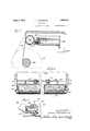
- FIG. l is a fragmentary sectional view through the forward end of a hektograph machine showing the moistener embodying the features of the present invention applied thereto;
- FIG. 2 is a plan view of the moistener as shown in Figure l with the platen and gelatine band of the machine removed;
- Figure 3 is a fragmentary sectional View through the forward end ofa hektograph machine showing a modified arrangement of moistening apparatus applied thereto;
- Figure d is a plan vlew of the modified moistener shown in Figure 3.
- FIG. 5 is an enlarged detail view of the valve mechanism employed in the modified form of moistener.
- the invention is, embodied in a machine wherein l0 represents the side frame members having the flat platen lsecured thereto to form the printing bed of the machine. Journaled Within the side frames at each end of the platen are spindles 14 upon which the matrix or gelatine band 16 is wound to form the rolls 18. The platen i. so that it is free to slide towards and from the gelatine band 16, which constitutes the operative and inoperative position of' the moistener, respectively.
- Theactuatingmechanismforoperating the moistener consists of aI foot pedal 28 which is pivoted to a suitable part of the machine at 29.
- a vertical link 30 and the horizontal arm 32 are so pivotally secured that movement imparted to the foot pedal will transmit through link 30 similar movement to the to the machine at 33 and is held under tension by spring 34.
- spring 34 which is in turn fastened to the disk 36 mounted for rotationqin the side frame 10 by means of a handle 38.
- This arrangement functions to increase the tension on the arm 32 by rotating the handle through 180.
- a tie rod 40 is secured to the side frames by means of nuts 41 and has mounted thereon,
- a tubular rod 42 A bell crank is secured to the rod 42 and consists of the arm 44 located at the extreme left hand end and a depending arm 46y at the right hand end as disclosed in Figure 2.
- a link 48 isl secured to the free end of arm 44 ,at 49 and to the free end of arm 32 through the slot 50 and pin 51.
- spring 34 are provided since the extreme right hand end of the arm 32 actuates mechanism to release a brake on the rear spindle through the movement imparted to the pedal 28. The normal position of the arm 32 and spring 34 tends to applypressure to the brake and thus to the spindle so that the gelatine band is maintained in a stretched condition over the surface of the platen.
- the depending arm 46 is directly connectedby means of a pin 52 to a U-shaped actuating bar 54 which in turn has direct engagement with the angle bar 56 secured to the waterv container 24.
- actuating bar 54 which in turn has direct engagement with the angle bar 56 secured to the waterv container 24.
- Springs 57 and 58 are provided to maintain the linkage in proper position and to hold the actuating bar 54 1n and is thereforenot shown engagement with the water container.
- the gelatine roll is .fed forward over ,the platen 12 and wound on the spindle 14 as horizontal arm 32.
- the arm 32 is pivoted
- the slot 50 and however, constitutes no part of the disclosed in Figure 1. It is, of course, understood that the winding of the band occurs only during successive printing operations when it is necessary to expose a clean portion of the gelatine for use. It is during these movements of the gelatine band that vthe moisture is operated.
- a disconnecting lever 60 is providedwhich, uponactuation, operates ya lever 62 directly connected thereto for acting as an abutment or stop upon the arm 44.
- a modied form of moistening device is disclosed in Figures 3 and 4, and is employed in connection with machines in which the printin bed extends well forward and almost'dlrectly over the axis of the gelatine rolls.
- the construction comprises a Water container 124 which is operated through an ⁇ Journaled within the trough in bearing members 175 is a felt-covered roller 120 for contact with the back surface of the bands 116.
- trough 170 is purposely made shallow and will therefore contain' very little said matrix extending between the spindle and bed, means for supporting said container for sliding movement and actuating means for sliding said container to bring sa1d roller into and out of contact With the said surface of the matrix.
- a gelatine band supported thereon, means for applying moisture to the gelatine surface comprising a container a aptcd to contain a quantity of Water, and means journaled 1n saidcontainer for contact with the opposite side of said band.
- means for applying moisture to the printing surface of said matrix including a roller journaled for contact with the opposite surface of said matrix.
- a duplicating machine in combination With a printing bed, a band adapted to be supported on said bed, a roller for contact with said band, a shallowr trough mounted adjacent said band and Within which said roller is j ournaled, a Water container secured to said trough, openings extending from said container to said trough and adapted to be normally closed by valves, means for actuating said valves by pressure against said roller, whereby when said roller contacts said band, said valves are actuated to cause said roller to apply Water to said bands.
- a duplicating machine in combination with a printing bed, a gelatine band V adapted to bc supported on saidbed, a roller for contact with said band, a shallow trough mounted adjacent said band and Within which said roller is journaled, a Water container secured to said trough and provided with openings extending into said trough, and means operatedby pressure against said roller for normally closing said openings.
- a gelatine band adapted to be supported on said bed, a yroller for contact With said band ⁇ a shallow trough mounted adjacent said band and Within which said roller is journaled, a water containersecured to said trough and provided with openings extending into said trough, valves for normally closing said openings, and means for imparting movement to said container to simultaneously cause said roller to contact said band and to actuate said valves.
- a matrix supported thereon means for applying moisture to the backing of the matrix, and spindles journaled in the frame at vthe ends of the printing bed upon which the matrix surface contacts the back of the adjacent inner convolution.
- a frame having a printing bed, a gelatin band supported thereon, means for applying moisture to the gelatin ⁇ surface of the band, including a member having contact wlth the opposite surface of the band, and spindles upon which the band is Wound, whereby the gelatin surface of one convolution contacts the back of the adjacent inner convolution. Signed at Chicago, Illinois, this 5th day of October. 1929. 1
- JOHN P. T'W'UERSOIL is Wound, whereby the printing surface of the matrix is maintained in a moistened con-
Description
April 5, 1932. P. PEDERSON 1,852,331
MOISTENER Filed Oct. 9, 1929 2 Sheets-Sheet l April 5, 1932. J. P. PEDERsoN 1,852,331
MOISTENER Filed Oct. Q 1929 2 Sheets-Sheet 2 lllli fdd Patented pn 5, 1932 iTED STATESl dllllfltl' W EPEDERSN, OF CHICAGO, ILLINUIS, ASSIGNOR TO DITTO, 1NCORPORATED, 0F GHCAGO, LLINIS, .A CORPORATION F WEST VIRGINIA MDISTENER application inea october a, i929. serial No. :3.913,324.
ll'he invention relates to' improvements in duplicating machines of the type employing a matriir adapted to receive impressions and roller means for pressing a master or copy sheet thereupon to communicate and receive the impressions, and has reference more particularly to novel means for maintaining the surface of the gelatine matrix in a it and .suitable condition for properly receiving and communicating the impressions.
The above type ofV duplicating machines are commonly lrnown as liektograph machimes9 and employ as a printingl medium a gelatine surface which is commercially supplied in the form of a canvas band or strip having a layer of gelatine cemented thereto, the whole being wound upon spindles to form gelatine rolls. ln the operation of the machines the gelatine band is fed from the roll over the flat platen or printing bed to expose a portion of the gelatine surface and is then wound upon another spindle journaled at the front end of the machine.
llt has become the practice immediately before the printing operation to sponge the surface of the gelatine bands with water, which has heretofore been done by the operator by using a sponge or other suitable means. The addition of Water to the gelatin-e has been found to be very beneficial as it renders the substance soft and pliable and therefore removes the undesirable brittleness from the printing surface. 'l`o render the feeding of the gelatine band over the platen surface as frictionless as possible and to maintain the gelatine in a soft and 4 yielding condition whereby the efficiency ofthe machine in communicating legible impressions is increased, the present invention provides for applying water in desired quantities to the gelatine surface through a novel form of apparatus.
Une of the objects of the present invention, therefore., is to provide hektograph machines with novel means for applying moistureto the surface of the gelatine matrix to maintain the gelatine in a soft and pliable condition during the time the rolls are stored for future use.
another object of the present invention is to provide helitograph machines with an improved device for ap lying moisture to'tiuv gelatineY surface whic may be thrown into and out of operation as desired.
Yet another object is to provide hektof graph machines with a novel form of apparatus for applying moisture to the gelatine bands during the feeding operation of A bodiment of the device and vwherein like reference characters are used to designate like parts* Figure l is a fragmentary sectional view through the forward end of a hektograph machine showing the moistener embodying the features of the present invention applied thereto;
c Figure 2 is a plan view of the moistener as shown in Figure l with the platen and gelatine band of the machine removed;
Figure 3 is a fragmentary sectional View through the forward end ofa hektograph machine showing a modified arrangement of moistening apparatus applied thereto;
Figure d is a plan vlew of the modified moistener shown in Figure 3; and
Figure 5 is an enlarged detail view of the valve mechanism employed in the modified form of moistener.
Referring particularly to Figuresll and 2 of the drawings, the invention is, embodied in a machine wherein l0 represents the side frame members having the flat platen lsecured thereto to form the printing bed of the machine. Journaled Within the side frames at each end of the platen are spindles 14 upon which the matrix or gelatine band 16 is wound to form the rolls 18. The platen i. so that it is free to slide towards and from the gelatine band 16, which constitutes the operative and inoperative position of' the moistener, respectively.
Theactuatingmechanismforoperating the moistener consists of aI foot pedal 28 which is pivoted to a suitable part of the machine at 29. A vertical link 30 and the horizontal arm 32 are so pivotally secured that movement imparted to the foot pedal will transmit through link 30 similar movement to the to the machine at 33 and is held under tension by spring 34.which is in turn fastened to the disk 36 mounted for rotationqin the side frame 10 by means of a handle 38. This arrangement functions to increase the tension on the arm 32 by rotating the handle through 180. l
A tie rod 40 is secured to the side frames by means of nuts 41 and has mounted thereon,
so that it is free to rotate, a tubular rod 42. A bell crank is secured to the rod 42 and consists of the arm 44 located at the extreme left hand end and a depending arm 46y at the right hand end as disclosed in Figure 2. A link 48 isl secured to the free end of arm 44 ,at 49 and to the free end of arm 32 through the slot 50 and pin 51. spring 34 are provided since the extreme right hand end of the arm 32 actuates mechanism to release a brake on the rear spindle through the movement imparted to the pedal 28. The normal position of the arm 32 and spring 34 tends to applypressure to the brake and thus to the spindle so that the gelatine band is maintained in a stretched condition over the surface of the platen. This construction, present invention in detail. p
The depending arm 46 is directly connectedby means of a pin 52 to a U-shaped actuating bar 54 which in turn has direct engagement with the angle bar 56 secured to the waterv container 24.` Springs 57 and 58 are provided to maintain the linkage in proper position and to hold the actuating bar 54 1n and is thereforenot shown engagement with the water container.
In the operation of the parts thus far described, the gelatine roll is .fed forward over ,the platen 12 and wound on the spindle 14 as horizontal arm 32. The arm 32 is pivoted The slot 50 and however, constitutes no part of the disclosed in Figure 1. It is, of course, understood that the winding of the band occurs only during successive printing operations when it is necessary to expose a clean portion of the gelatine for use. It is during these movements of the gelatine band that vthe moisture is operated. Pressure is exerted upon the foot pedal 28 by-the operator which'imparts a downward movement to the arm 32 until the pin 51 reaches the bottom of slot 50, whereupon further actuation of the arm 32 exerts a downward movement to link 48, which is in turn imparted to the arm y44 to cause rotation to the tubular rod 42. Rotation of rod 42 causes the depending arm 46 to swing. towardsl the front of the machine, thereby actuating in like manner the U- shaped bar 54 which in turn causes the water container 24 to slide on the` guide bars 26 towards the gelatine band.` This forward movement of the water container actuates the felt covered roller 2O to Contact with the back surface of the band 16 and, as the band is wound upon the spindle 14 during successive feeding operatlons, a film of water or moisture is distributed over its entire back surface. As the gelatine surface contacts with the back of the bands when wound upon the rolls, the gelatine is therefore kept in a moist condition during the time the rolls are stored, and the surface remains soft and pliable and better able to receive and communicate impressions the next time it is used.
It is sometimesdesirable to discontinue the use of the moistening device in which case actuation of the pedal will function to operate only the brake mechanism in connection with the arm 32. For this purpose' a disconnecting lever 60 is providedwhich, uponactuation, operates ya lever 62 directly connected thereto for acting as an abutment or stop upon the arm 44. When the lever is turned so that the arm 62 assumes the dotted position shown in Figure 1 the water container 24 and roller 20 remain in retracted position.
A modied form of moistening device is disclosed in Figures 3 and 4, and is employed in connection with machines in which the printin bed extends well forward and almost'dlrectly over the axis of the gelatine rolls. The construction comprises a Water container 124 which is operated through an `Journaled within the trough in bearing members 175 is a felt-covered roller 120 for contact with the back surface of the bands 116.
As the trough 170 is purposely made shallow and will therefore contain' very little said matrix extending between the spindle and bed, means for supporting said container for sliding movement and actuating means for sliding said container to bring sa1d roller into and out of contact With the said surface of the matrix.
8. In a duplicating machine, in combination With a frame and a printing bed, a gelatine band supported thereon, means for applying moisture to the gelatine surface comprising a container a aptcd to contain a quantity of Water, and means journaled 1n saidcontainer for contact with the opposite side of said band.
9. In a device of the class described, in combination With a matrix, means for applying moisture to the printing surface of said matrix, including a roller journaled for contact with the opposite surface of said matrix.
10. In 'a duplicating machine, in combination With a printing bed, a band adapted to be supported on said bed, a roller for contact with said band, a shallowr trough mounted adjacent said band and Within which said roller is j ournaled, a Water container secured to said trough, openings extending from said container to said trough and adapted to be normally closed by valves, means for actuating said valves by pressure against said roller, whereby when said roller contacts said band, said valves are actuated to cause said roller to apply Water to said bands.
11. 'In a duplicating machine, in combination with a printing bed, a gelatine band V adapted to bc supported on saidbed, a roller for contact with said band, a shallow trough mounted adjacent said band and Within which said roller is journaled, a Water container secured to said trough and provided with openings extending into said trough, and means operatedby pressure against said roller for normally closing said openings.
12. In a duplicating machine, in combination With a printing bed, a gelatine band adapted to be supported on said bed, a yroller for contact With said band` a shallow trough mounted adjacent said band and Within which said roller is journaled, a water containersecured to said trough and provided with openings extending into said trough, valves for normally closing said openings, and means for imparting movement to said container to simultaneously cause said roller to contact said band and to actuate said valves. K
13. In a duplicating machine,'in combination with a frarr. and a printing bed, a matrix supported thereon, means for applying moisture to the backing of the matrix, and spindles journaled in the frame at vthe ends of the printing bed upon which the matrix surface contacts the back of the adjacent inner convolution.
14. In a duplicating machine, in comblnation, a frame having a printing bed, a gelatin band supported thereon, means for applying moisture to the gelatin `surface of the band, including a member having contact wlth the opposite surface of the band, and spindles upon which the band is Wound, whereby the gelatin surface of one convolution contacts the back of the adjacent inner convolution. Signed at Chicago, Illinois, this 5th day of October. 1929. 1
JOHN P. T'W'UERSOIL is Wound, whereby the printing surface of the matrix is maintained in a moistened con-
Priority Applications (1)
| Application Number | Priority Date | Filing Date | Title |
|---|---|---|---|
| US398324A US1852331A (en) | 1929-10-09 | 1929-10-09 | Moistener |
Applications Claiming Priority (1)
| Application Number | Priority Date | Filing Date | Title |
|---|---|---|---|
| US398324A US1852331A (en) | 1929-10-09 | 1929-10-09 | Moistener |
Publications (1)
| Publication Number | Publication Date |
|---|---|
| US1852331A true US1852331A (en) | 1932-04-05 |
Family
ID=23574938
Family Applications (1)
| Application Number | Title | Priority Date | Filing Date |
|---|---|---|---|
| US398324A Expired - Lifetime US1852331A (en) | 1929-10-09 | 1929-10-09 | Moistener |
Country Status (1)
| Country | Link |
|---|---|
| US (1) | US1852331A (en) |
-
1929
- 1929-10-09 US US398324A patent/US1852331A/en not_active Expired - Lifetime
Similar Documents
| Publication | Publication Date | Title |
|---|---|---|
| US2067289A (en) | Apparatus for multiplying records | |
| US1852331A (en) | Moistener | |
| US2830534A (en) | Duplicating machine | |
| US2299994A (en) | Moistening mechanism | |
| US3648609A (en) | Apparatus for activating a printing master | |
| US2072534A (en) | Duplicating machine and method | |
| US2264578A (en) | Moistening apparatus | |
| US3444807A (en) | Drive means for duplicating apparatus using master cards | |
| US1204118A (en) | Machine for banding bills and the like. | |
| US1222592A (en) | Method for erasing type-written matter. | |
| US2708404A (en) | Tape feeding means for hectographic duplicating machines | |
| US2539839A (en) | Moistening control device for duplicating machines | |
| US2271801A (en) | Moistening mechanism | |
| US2278197A (en) | Duplicating machine | |
| US2275455A (en) | Duplicating machine | |
| US2313127A (en) | Moistening mechanism | |
| US1990349A (en) | Manifolding machine | |
| US2342524A (en) | Means for moistening pieces of paper and like material | |
| US2130600A (en) | Duplicating apparatus | |
| US1957483A (en) | Method and apparatus for multiplying records | |
| US1890915A (en) | Duplicating means and method | |
| US2465994A (en) | Device for producing typewritten master sheets | |
| US1019312A (en) | Copying-machine. | |
| US2536606A (en) | Master sheet advancing means for duplicating machines | |
| US1118119A (en) | Multiple-copying machine. |