US1852330A - Pressure regulating apparatus for elastic fluids - Google Patents
Pressure regulating apparatus for elastic fluids Download PDFInfo
- Publication number
- US1852330A US1852330A US19741727A US1852330A US 1852330 A US1852330 A US 1852330A US 19741727 A US19741727 A US 19741727A US 1852330 A US1852330 A US 1852330A
- Authority
- US
- United States
- Prior art keywords
- conduit
- pressure
- fluid
- pressure regulating
- regulating apparatus
- Prior art date
- Legal status (The legal status is an assumption and is not a legal conclusion. Google has not performed a legal analysis and makes no representation as to the accuracy of the status listed.)
- Expired - Lifetime
Links
- 239000012530 fluid Substances 0.000 title description 22
- 230000001105 regulatory effect Effects 0.000 title description 4
- 230000004888 barrier function Effects 0.000 description 9
- 238000004891 communication Methods 0.000 description 6
- 230000006854 communication Effects 0.000 description 6
- 230000033228 biological regulation Effects 0.000 description 1
- 238000002485 combustion reaction Methods 0.000 description 1
- 238000001816 cooling Methods 0.000 description 1
- 238000010586 diagram Methods 0.000 description 1
- 230000006698 induction Effects 0.000 description 1
- 230000004941 influx Effects 0.000 description 1
- 238000012986 modification Methods 0.000 description 1
- 230000004048 modification Effects 0.000 description 1
Images
Classifications
-
- G—PHYSICS
- G05—CONTROLLING; REGULATING
- G05D—SYSTEMS FOR CONTROLLING OR REGULATING NON-ELECTRIC VARIABLES
- G05D16/00—Control of fluid pressure
- G05D16/04—Control of fluid pressure without auxiliary power
-
- Y—GENERAL TAGGING OF NEW TECHNOLOGICAL DEVELOPMENTS; GENERAL TAGGING OF CROSS-SECTIONAL TECHNOLOGIES SPANNING OVER SEVERAL SECTIONS OF THE IPC; TECHNICAL SUBJECTS COVERED BY FORMER USPC CROSS-REFERENCE ART COLLECTIONS [XRACs] AND DIGESTS
- Y10—TECHNICAL SUBJECTS COVERED BY FORMER USPC
- Y10T—TECHNICAL SUBJECTS COVERED BY FORMER US CLASSIFICATION
- Y10T137/00—Fluid handling
- Y10T137/8593—Systems
- Y10T137/85978—With pump
- Y10T137/85986—Pumped fluid control
Definitions
- the invention may be said to consist esseir tially in an apparatus for maintaining the pressure of a flow of fluid at a given pressure, comprising a conduit for such flow oi. fluid, a bv-pass affording; open communication between the interior of said. conduit and a region wherein such given pressure obtains, and means restricting the rate of flow ot fluid alone: said conduit to said by'pass to a value which will enable fluid to traverse said bypass to said region without any substantial change in pressure along said by-pass.
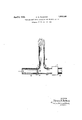
- This drawinp illustrates a conduit 35, a barrier 23? located within the conduit and provided with a materially reduced opening 38, and an open ended branch pipe 39 connecting said conduit on the delivery side of said barrier directly with atmosphere.
- the barrier serves to restrict the How of gas therebeyond to a value which is able to escape through the pipe 39 without raising the pressure upon the delivery side of aid barrier above atmospl'leric pressure, whereas the outward flow of gas through said pipe 39 effectively prevents induction of air.
- the gas so issuing from the pipe 89 is ordinarily ignited and burned to avoid pollution of the surrounding air.
- a pressure regulator for gaseous fluids comprising a conduit, a barrier located at one end of said conduit and provided with a restricted opening, the other end of said conduit being unrestricted, means for withdrawing fluid from. the last mentioned end of said conduit, and means located beyond said barrier, with reference to the direction of flow of fluid within said conduit, allording open communication between the interior of said conduit and a region wherein given pressure conditions obtain.
- a pressure regulator for gaseous fluids comprising a conduit, a barrier located at one end of said conduit and provided with a restricted opening, the other end of said conduit having an unrestricted passage, means for withdrawing fluid from the last mentioned end of said conduit, and means affording open communication between the interior of said conduit and atmosphere.
- Apparatus for maintaining the pressure of a flow of gaseous fluid of a given value comprising a conduit for such flow of fluid, a by-pass located intermediate the inlet and outlet ends of said conduit and affording 7 open communication between the interior of the latter and a region wherein such pressure of given value obtains, and means restricting the rate of flow of fluid along said conduit to said by-pass to a value which will enable fluid to traverse said by-pass to said region without any substantial change in pressure along said by-passf the unrestricted outlet end of said conduit constithe intake end of a fluid pump whereby said flow of fluid is eflected.
Landscapes
- Physics & Mathematics (AREA)
- Fluid Mechanics (AREA)
- General Physics & Mathematics (AREA)
- Engineering & Computer Science (AREA)
- Automation & Control Theory (AREA)
- Pipeline Systems (AREA)
Description
April 5, 1932. H. N.- PACKARD PRESSURE REGULATING APPARATUS FOR ELASTIC FLUIDS Original Filed Jan. 28, 1921 INVENTOR. M ,PMW,
ATTORNEY.
Patented Apr. 5, 1932 HORACE N. PACKARD, F OSSINING, NEW YORK, ASSIGNOR,
BY MESNE assrelvmtnn rs, To
CUTLER-HAIMMER, INC., A CORPORATION OF DELAWARE PRESSURE REGULA'IIN Gr APPARATUS FOR ELASTIC FLUIDS Original application filed January 28, 1921, Serial No. census. Divided and this application filed June 8 1927. Serial This invention relates to pressure regulating apparatus for elastic fluids and has for its object to provide a simple and inexpenswe regulator whereby a stream of suclrfluid may lJBtlQllVQlGfl at a pressure which wlthin very fine limits equal to a certain given pressure. While not limited thereto the invention is especially applicable to the pressure regulation of the test being delivered to'the burner of a gas calorimeter, when it is desired that said test shall be delivered at atmospheric pressure.
This application is a division of my copending application Serial No. 440,615, filed January 28, 1921, which has resulted 1n Patent No. 1,662,802, dated March 13, 1,928.
The invention may be said to consist esseir tially in an apparatus for maintaining the pressure of a flow of fluid at a given pressure, comprising a conduit for such flow oi. fluid, a bv-pass affording; open communication between the interior of said. conduit and a region wherein such given pressure obtains, and means restricting the rate of flow ot fluid alone: said conduit to said by'pass to a value which will enable fluid to traverse said bypass to said region without any substantial change in pressure along said by-pass.
One embodiment of the invention is 11111- trated in the accompanying drawing and the same will now be described, it being understood that the embodiment illustrated is susceptible of various modifications without departing from the scope of the appended claims.
This drawinp illustrates a conduit 35, a barrier 23? located within the conduit and provided with a materially reduced opening 38, and an open ended branch pipe 39 connecting said conduit on the delivery side of said barrier directly with atmosphere. In operation the barrier serves to restrict the How of gas therebeyond to a value which is able to escape through the pipe 39 without raising the pressure upon the delivery side of aid barrier above atmospl'leric pressure, whereas the outward flow of gas through said pipe 39 effectively prevents induction of air. The gas so issuing from the pipe 89 is ordinarily ignited and burned to avoid pollution of the surrounding air. efilun' of i said tube y gas drawn into the pump (shown diagram matically at2) constitutes a true sample ot the main supply undergoing'testl This apparatus may conveniently be adopted in connection withthe calorimetric device described in my patent aforementioned lor insuring that the test gas drawn intothe ga pump? and delivered to the burner shall be of atmospheric pressure.
lnthis way provision may be made for supplying test gas as well as combustion air and cooling a "to the device illustratd in said pg tentunder like conditions of temp'crzi ture, pressure and'saturation and in constant volumetric proportions with respect tooIie another, such proportions moreover being unaffected by variation in speed of the driving motor.
What I claim as new and desire to secure by Letters Patent is:
1. A pressure regulator for gaseous fluids comprising a conduit, a barrier located at one end of said conduit and provided with a restricted opening, the other end of said conduit being unrestricted, means for withdrawing fluid from. the last mentioned end of said conduit, and means located beyond said barrier, with reference to the direction of flow of fluid within said conduit, allording open communication between the interior of said conduit and a region wherein given pressure conditions obtain.
Such continuous gas 111 appreciable quantities fi'om 2. A pressure regulator for gaseous fluids comprising a conduit, a barrier located at one end of said conduit and provided with a restricted opening, the other end of said conduit having an unrestricted passage, means for withdrawing fluid from the last mentioned end of said conduit, and means affording open communication between the interior of said conduit and atmosphere.
8. The combination with a fluid pump having an intake conduit, of means affording open communication between the interior of said conduit and atmosphere and means restricting the flow of fluid toward said former means and said pump to a value which is further serves to insure thatthe test tuting able to escape through said former means without efl'ecting a rise in pressure within the conduit adjacent the pump while providing against influx of fluid through said former means to said conduit.
4. The combination with a pump having an intake conduit, of pressure regulating means therefor comprising a barrier located in said conduit and having a restricted opening and a tube connected to said conduit between said barrier and said pump for affording direct and unrestricted communica tion between the interior of said conduit and atmosphere.
5. Apparatus for maintaining the pressure of a flow of gaseous fluid of a given value, comprising a conduit for such flow of fluid, a by-pass located intermediate the inlet and outlet ends of said conduit and affording 7 open communication between the interior of the latter and a region wherein such pressure of given value obtains, and means restricting the rate of flow of fluid along said conduit to said by-pass to a value which will enable fluid to traverse said by-pass to said region without any substantial change in pressure along said by-passf the unrestricted outlet end of said conduit constithe intake end of a fluid pump whereby said flow of fluid is eflected.
In witness whereof I have hereunto subscribed my name.
HORACE N; PACKARD.
Priority Applications (1)
| Application Number | Priority Date | Filing Date | Title |
|---|---|---|---|
| US19741727 US1852330A (en) | 1927-06-08 | 1927-06-08 | Pressure regulating apparatus for elastic fluids |
Applications Claiming Priority (1)
| Application Number | Priority Date | Filing Date | Title |
|---|---|---|---|
| US19741727 US1852330A (en) | 1927-06-08 | 1927-06-08 | Pressure regulating apparatus for elastic fluids |
Publications (1)
| Publication Number | Publication Date |
|---|---|
| US1852330A true US1852330A (en) | 1932-04-05 |
Family
ID=26892836
Family Applications (1)
| Application Number | Title | Priority Date | Filing Date |
|---|---|---|---|
| US19741727 Expired - Lifetime US1852330A (en) | 1927-06-08 | 1927-06-08 | Pressure regulating apparatus for elastic fluids |
Country Status (1)
| Country | Link |
|---|---|
| US (1) | US1852330A (en) |
-
1927
- 1927-06-08 US US19741727 patent/US1852330A/en not_active Expired - Lifetime
Similar Documents
| Publication | Publication Date | Title |
|---|---|---|
| US2692800A (en) | Nozzle flow control | |
| US2271982A (en) | Homogenization of liquid matter | |
| US2147568A (en) | Gas shut-off means for mixing apparatus | |
| US1852330A (en) | Pressure regulating apparatus for elastic fluids | |
| US1739161A (en) | Multistage fuel mixer | |
| US2321483A (en) | Proportional mixer | |
| US2388939A (en) | Pump for fuel systems | |
| US2155279A (en) | Fluid flow control apparatus | |
| US2265737A (en) | Fluid control apparatus | |
| GB1071984A (en) | Apparatus for the catalytic combustion of exhaust gases from internal combustion engines | |
| DE2235857B2 (en) | Heating device for the intake system of a water-cooled internal combustion engine | |
| US2095824A (en) | Fluid system | |
| US2064244A (en) | Fluid mixing device | |
| ES403636A1 (en) | Inert gas supply apparatus for an oil tanker | |
| US2452300A (en) | Supercharger | |
| US1931781A (en) | Flow control device | |
| US2239292A (en) | Fuel regulator for motor temperature conditions | |
| GB183407A (en) | Improvements in or relating to pressure regulating devices | |
| US1290715A (en) | Air-mixer. | |
| US1609163A (en) | Auxiliary air-inlet device for use with internal-combustion engines | |
| ES423988A1 (en) | Fuel/air separation system for diesel engines optical system for transmit/receive mode conditioning of facsimile t | |
| US2438311A (en) | Pump discharge fitting | |
| US1550255A (en) | Method of and apparatus for maintaining a variable supply of gaseous fluids for combustion | |
| US1738160A (en) | Gas flash light apparatus | |
| GB260357A (en) | Improvements in or relating to heating or cooling apparatus for air or other gases |