US1852326A - Throttle - Google Patents
Throttle Download PDFInfo
- Publication number
- US1852326A US1852326A US23729027A US1852326A US 1852326 A US1852326 A US 1852326A US 23729027 A US23729027 A US 23729027A US 1852326 A US1852326 A US 1852326A
- Authority
- US
- United States
- Prior art keywords
- throttle
- piston
- steam
- valve
- chamber
- Prior art date
- Legal status (The legal status is an assumption and is not a legal conclusion. Google has not performed a legal analysis and makes no representation as to the accuracy of the status listed.)
- Expired - Lifetime
Links
- 238000005192 partition Methods 0.000 description 15
- 230000003137 locomotive effect Effects 0.000 description 11
- 210000000038 chest Anatomy 0.000 description 2
- 238000010276 construction Methods 0.000 description 2
- 206010022000 influenza Diseases 0.000 description 2
- MXBCYQUALCBQIJ-RYVPXURESA-N (8s,9s,10r,13s,14s,17r)-13-ethyl-17-ethynyl-11-methylidene-1,2,3,6,7,8,9,10,12,14,15,16-dodecahydrocyclopenta[a]phenanthren-17-ol;(8r,9s,13s,14s,17r)-17-ethynyl-13-methyl-7,8,9,11,12,14,15,16-octahydro-6h-cyclopenta[a]phenanthrene-3,17-diol Chemical compound OC1=CC=C2[C@H]3CC[C@](C)([C@](CC4)(O)C#C)[C@@H]4[C@@H]3CCC2=C1.C1CC[C@@H]2[C@H]3C(=C)C[C@](CC)([C@](CC4)(O)C#C)[C@@H]4[C@@H]3CCC2=C1 MXBCYQUALCBQIJ-RYVPXURESA-N 0.000 description 1
- 238000002485 combustion reaction Methods 0.000 description 1
- 239000002131 composite material Substances 0.000 description 1
- 238000007689 inspection Methods 0.000 description 1
- 239000000463 material Substances 0.000 description 1
- 230000000750 progressive effect Effects 0.000 description 1
Images
Classifications
-
- F—MECHANICAL ENGINEERING; LIGHTING; HEATING; WEAPONS; BLASTING
- F22—STEAM GENERATION
- F22G—SUPERHEATING OF STEAM
- F22G7/00—Steam superheaters characterised by location, arrangement, or disposition
- F22G7/06—Steam superheaters characterised by location, arrangement, or disposition in furnace tubes
- F22G7/065—Steam superheaters characterised by location, arrangement, or disposition in furnace tubes for locomotive boilers
-
- Y—GENERAL TAGGING OF NEW TECHNOLOGICAL DEVELOPMENTS; GENERAL TAGGING OF CROSS-SECTIONAL TECHNOLOGIES SPANNING OVER SEVERAL SECTIONS OF THE IPC; TECHNICAL SUBJECTS COVERED BY FORMER USPC CROSS-REFERENCE ART COLLECTIONS [XRACs] AND DIGESTS
- Y10—TECHNICAL SUBJECTS COVERED BY FORMER USPC
- Y10T—TECHNICAL SUBJECTS COVERED BY FORMER US CLASSIFICATION
- Y10T137/00—Fluid handling
- Y10T137/8593—Systems
- Y10T137/86928—Sequentially progressive opening or closing of plural valves
- Y10T137/86936—Pressure equalizing or auxiliary shunt flow
- Y10T137/86944—One valve seats against other valve [e.g., concentric valves]
- Y10T137/86952—Locomotive throttle
Definitions
- This invention relatesA to locomotives and particularly to superheatei' headers and multiple ⁇ throttles such as disclosed in United States patent to R. M. Brown, Reissue #16,285 of March 9, 1926.
- a balanced form for such multiple tlirottles is shown and claimed in my United States Patent #1,712,982, dated May 14, 1929.
- the present invention constitutes an improvement y) on the disclosure in my application and has ttor its purpose the provision of an arrangement using such balanced throttles which gives sufficient steam for maneuvering the locomotive in tight places as well as for in', drifting, and for insuring the closing of the tlirottles when the engineer manipulates his lever to this end ⁇
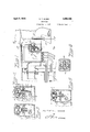
- the invention is illustrated in the two sheets of drawings filed herewith, in which Fig.
- FIG. 1 is a central, vertical, longitudinal section ot' the front upper part of a locomotive illustrating a superheater header with my invention applied, only enough of the locomotivebeingshownto make clear the relative poi5 sitionotmyimprovement
- Fig. 2 is a composite figure, the left half being a section on line 2er-2A, while the right halt ⁇ is a section on .2B-*2B ot' Fig. 1;
- Figs. 3, fl and 5 are enlarged views of the throttle and it-s housing 50 as they appear in Fig. ⁇ 1, these figures illustrating three different positions of the valve, and Fig. 6 is a section on line 6-6 of Fig. 5.
- the locomotive in connection with which I have sho-wn my invention is of any ordinary or desired type equipped with a flue or other superheater.
- the front i'lue sheet 1 has, eX- tending backward from it toward the tirebox, the tlues 2. These flues deliver the products of combustion from the 1irc-boX to the smoke-box ot the locomotive whence they escape through the stack extension 3 and the stach 3c.
- Into the flues 2 extend the tubular superheater units or elements l: whose ends are secured to the header 5.
- This superheat- V er header 5 comprises two sets ot intermeshed fingers or branches according to the ordinary well known construction, which needs no detailed description here.
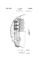
- the hollow cylindrical interior of the cap 17 has an annular downwardly extending portion 20 separating the annular space 21 from the cylindrical interior space 22.
- the piston is provided with a cylindrical cavity 23 so that the body portion of this piston is annular in shape, sliding into the annular space 21. The ht between these two is made very loose both ou the outer and inner sides ot the annular piston body for nthe purpose stated more fully hereinafter.
- the valvestein 13 has a cylindrical bore extending lengthwise through. it coaXially with the hollow interior of the piston 19. From the lower portion of the space 23 a plurality of passages 24 eXtend through the valve putting the space 23 into communication with the chamber 9. Above these passages 24 is a seat 25 controlled by the pilot valve 26.
- This pilot valve has a stem 27 extending downward through the bore of the steam 13. From chamber 7 a plurality of passages 28 extend to the upper portion of the cylindrical space 22.
- the pilot valve'26 has a plurality of notches 29 at its upper end extending downward a short distance as will be clear from Figs. 3 to 5. These notches appear in plan in Fig. 6.
- each throttle with its associated pilot valve may be described as follows: In its closed position with both the main throttleV 12 and the pilot valve 26.0nV their seats, steam from chamber 7 under boiler pressure has filled the space 22 above valve 26, has passed through thenotches 29 as well as through'the clearance around the piston 19 into the annular space 21. The main throttle and the valve are therefore held on their seats by full boiler pressure against whatever pressure exists in chamber 9.
- the cam 14 engages the stem '27 ahead of the stem 13-and raises the pilot valve 26 from its seat.
- the pilot valve is comparatively small and no great effort is required to open it. This permits the steam from chamber 21 tol escape through the passages ⁇ 24.
- An essential feature of my invention is that ⁇ 'the pilot valves are raised one after another',
- the second cam 14 from the right has raised its pilot valve a little distance, and the third cam 14 has raised its pilot valve 26 still more.
- This progressive arrangement may ext-end from one end of the shaft to the other or the successive raising can occur in any desired other sequence.
- two valves may be raised at a time.
- the pilots of I and IA open first, followed by the opening II and IIA, and then by that of HI and IIIA. It is lLonly after all of the pilot valves have been raised off their ⁇ seats that the first main valve is engaged by its cam 14.
- the sequence of, events may be summarized as follows: The first pilot valve is engaged by its cam and opens. The second one.. is similarly raised and so on until they are all opened.
- the notches of the first valve are closed oft lby the annular portion 20.
- Main valve No. 1 is opened- .
- the notches of the second valve are closed olf.
- the main valve No. 2 then opens.
- the notches of No. 8 are cut off, and valve No. 3 next opens, and
- a locomotive the combination of'a header, a horizontal partition therein having a plurality of ports, a corresponding number of Vthrottles each controlling Yone of said partition ports and each provided with a baleach throttle having a piston chamber therein in which the piston lits loosely and reciprocates, each throttle having a port placing the piston chamber into communication with the space below the throttle, a like number of pilot valves each controlling one of the ports throug'h the throttles, actuating mechanism to open said throttles and pilot valves in such order that all of the latter are opened before the first of the throttles is opened, and means controlled by the pilot valves to admit steam to the space below the throttles in addition to the steam released by them from the caps.
- a header having a plurality of ports, a corresponding number of throttles each controlling one of said partition ports and each provided with a balancing piston at its upper end, a cap above each throttle having a piston chamber therein in which the piston lits loosely and reciprocates, each throttle having a port placing the piston chamber into communication with the space below the throttle, alike number of pilot valves each controlling one of the ports through the throttles, actuating mechanism to open said throttles and pilot valves in such order that all of the latter are opened before the rst of the throttles is opened, and means to admit steam to the space below the throttles in addition to the steam released by the pilot valves from the caps, the additional steam supply being cut off by the pilot valves when they are seated and also when they are raised from their seats beyond a certain point.
- a header having a plurality of ports, a corresponding number of throttles each controlling one of said partition ports and each provided with a balancing piston at its upper end, a cap above each throttle having a piston chamber therein in which the piston fits loosely and reciprocates, each throttle having a port placing the piston chamber into communication with the space below the throttle, a like number of pilot valves each controlling one of the ports through the throttles, actuating mechanism to open said throttles and pilot valves in such order that all of the latter are opened before the first of the throttles is opened, and means to admit steam to the space below the throttles in addition to the steam released by the pilot valves from the caps, the additional steam supply being cut off by the pilot valves when they are seated and also when they are raised from their seats beyond a certain point, the arrangement being such that each pilot valve shuts off its additional steam supply just before the corresponding throttle is raised.
- a balancing piston secured to the upper side of the throttle, a cap above the throttle having a piston chamber in which the piston reciprocates, a
- 1hollow stem extending downwardly from the throttle, there being acylindrieal cavity extending into the upper side of the piston and a port from the bottom of said cavity to nular wall being a little above the top of the piston when the throttle is seated, and a cylindrical pilot valve adapted to close the port in the throttle and to reciprocate in the interior of the annular wall, portions being cut away at the upper end ofthe pilot valve to permit communication between the inside of the annular wall and the cylindrical space in the piston while the pilot valve is not ab-ove a certain selected position, a stem extending downwardly from the pilot valve through the interior of the throttle stem of such length that when the pilot valve is seated its stem extends beyond the throttle stem, and means to bear upwardly successively against the lower ends of the pilot valve stem and the throttle stem and so to raise them.
- a header having a plurality of ports; a corresponding number of throttles each controlling one of the ports, and individual balancing means for each throttle comprising a piston, a piston chamber, and a pilot valve; each throttle having associated with it a passage also controlled Vby its pilot valve Yto convey steam from one side of the partition to the other when the throttle is closed.
- Apparatus in accordance with claim 8 comprising means for operating thethrottles and pilot Valves so arranged that all of the pilot valves are opened before the first throttle opens, and that each of said passages is closed off before the associated throttle Y,
Landscapes
- Engineering & Computer Science (AREA)
- Mechanical Engineering (AREA)
- General Engineering & Computer Science (AREA)
- Control Of Turbines (AREA)
Description
` Apri; 5, 1932. N, T. MCKE 1,852,326
THROTTLE Filed Dec. 2, 1927 2 Sheets-Sheet l /lw/T/Vfm. INVENTOR BY Ila Zava ATTORNEY April 5, 1932. N. T. MGKEE 1,1852,326
THROTTLE Filed Dec. 2, 1927 2 Sheets-Sheet 2 IIL W s `N r N (w vr N I I 'h f Y I BY v Q ATTORNEY Patented Apr. 5, 1932 UNITED STATES PATENT u OFFICE T. MCKEE, OF BRONXVILLE, NEW YORK, ASSIGNOR TO AMERICAN THROTTLE COMPANY, ING., OF NEW YORK, N. Y.
THROTTLE Application filed December 2, 1927. Serial No. 237.1290.
This invention relatesA to locomotives and particularly to superheatei' headers and multiple` throttles such as disclosed in United States patent to R. M. Brown, Reissue #16,285 of March 9, 1926. A balanced form for such multiple tlirottles is shown and claimed in my United States Patent #1,712,982, dated May 14, 1929. The present invention constitutes an improvement y) on the disclosure in my application and has ttor its purpose the provision of an arrangement using such balanced throttles which gives sufficient steam for maneuvering the locomotive in tight places as well as for in', drifting, and for insuring the closing of the tlirottles when the engineer manipulates his lever to this end` The invention is illustrated in the two sheets of drawings filed herewith, in which Fig. 1 isa central, vertical, longitudinal section ot' the front upper part of a locomotive illustrating a superheater header with my invention applied, only enough of the locomotivebeingshownto make clear the relative poi5 sitionotmyimprovement Fig. 2 isa composite figure, the left half being a section on line 2er-2A, while the right halt` is a section on .2B-*2B ot' Fig. 1; Figs. 3, fl and 5 are enlarged views of the throttle and it-s housing 50 as they appear in Fig.` 1, these figures illustrating three different positions of the valve, and Fig. 6 is a section on line 6-6 of Fig. 5. The locomotive in connection with which I have sho-wn my invention is of any ordinary or desired type equipped with a flue or other superheater. The front i'lue sheet 1 has, eX- tending backward from it toward the tirebox, the tlues 2. These flues deliver the products of combustion from the 1irc-boX to the smoke-box ot the locomotive whence they escape through the stack extension 3 and the stach 3c. Into the flues 2 extend the tubular superheater units or elements l: whose ends are secured to the header 5. This superheat- V er header 5 comprises two sets ot intermeshed fingers or branches according to the ordinary well known construction, which needs no detailed description here. Steam is delivered to the superheater header by the dry-pipe 6, Hows through the superh'eater units or elements 1 and is delivered by them back into the header 5 from which it flows into the transverse chamber 7. The partition 8 divides chamber 7 from the transverse chamber 9, the latter communicating with the two steam pipes 10 (only one showing) which convey the steam to the two steam chests. Chamber 7 communicates with chamber 9 through a series of ports 11 which are controlled by valves or throttles 12. These valves have downwardly extending stems 18 which are engaged by cams 14 on shaft 15 and are raised by a counter-clockwise movement of the shaft as viewed in the drawings.v In alinement with each valve 12 is an opening 16 in the upper wall of the chamber 7 which is closed 'by the cap 17. This cap has a cylindrical bore 18 in it in which reciprocates the piston 19 unitary with thevalve 12.
As far as described, this arrangement is like that described in my former application. My improvement in the present case resides in the peculiar construction of the pilot valves and associated parts which I shall next describe.
The hollow cylindrical interior of the cap 17 has an annular downwardly extending portion 20 separating the annular space 21 from the cylindrical interior space 22. The piston is provided with a cylindrical cavity 23 so that the body portion of this piston is annular in shape, sliding into the annular space 21. The ht between these two is made very loose both ou the outer and inner sides ot the annular piston body for nthe purpose stated more fully hereinafter. The valvestein 13 has a cylindrical bore extending lengthwise through. it coaXially with the hollow interior of the piston 19. From the lower portion of the space 23 a plurality of passages 24 eXtend through the valve putting the space 23 into communication with the chamber 9. Above these passages 24 is a seat 25 controlled by the pilot valve 26. This pilot valve has a stem 27 extending downward through the bore of the steam 13. From chamber 7 a plurality of passages 28 extend to the upper portion of the cylindrical space 22. The pilot valve'26 has a plurality of notches 29 at its upper end extending downward a short distance as will be clear from Figs. 3 to 5. These notches appear in plan in Fig. 6.
The action of each throttle with its associated pilot valve may be described as follows: In its closed position with both the main throttleV 12 and the pilot valve 26.0nV their seats, steam from chamber 7 under boiler pressure has filled the space 22 above valve 26, has passed through thenotches 29 as well as through'the clearance around the piston 19 into the annular space 21. The main throttle and the valve are therefore held on their seats by full boiler pressure against whatever pressure exists in chamber 9. When the shaft 15 is rotated to open one of the throttles, the cam 14 engages the stem '27 ahead of the stem 13-and raises the pilot valve 26 from its seat. The pilot valve is comparatively small and no great effort is required to open it. This permits the steam from chamber 21 tol escape through the passages` 24. Additional steam will flow through passages 28, through space 22, through the notches 29 and out through the passages 24 as long as valve 26 is not raised beyond the point where the annular wall 20 closes off the notches 29. `When the valve is raised to the point where the notches are closed off, the steam flow described ceases. Further movement of the shaft 15 begins to raise the mainthrottle 12. This is not diflicult as the main throttle is then substantially balanced by the steam which has passed into the steam pipes and connected spaces. The clearance between the annular wall 2O and the annular piston 19 is made larger than that between the cylindrical bore of the cap and the body 19 so that thesteam from the annular space 21 will escape more rapidly toward the chamber 9 and the steam chests than new steam is supplied from the chamber 7.
`The cam 14 has now begun to engage the lower end of main piston stem 13 and further movement of the shaft 15 raises the pilot valve 26 together with the main throttle 12 until they reach the uppermost position as shown in Fig. 5.
An essential feature of my invention is that `'the pilot valves are raised one after another',
all of them being opened before the first main valve is raised. This will appear from an inspection of Fig..2 where the right hand cam 14 is just about to raise the pilot valve 26; the
.but none of the main valves.
' to the cylinders.
second cam 14 from the right has raised its pilot valve a little distance, and the third cam 14 has raised its pilot valve 26 still more. This progressive arrangement may ext-end from one end of the shaft to the other or the successive raising can occur in any desired other sequence. If desired, two valves may be raised at a time. Thus in the form illustrated, the pilots of I and IA. open first, followed by the opening II and IIA, and then by that of HI and IIIA. It is lLonly after all of the pilot valves have been raised off their `seats that the first main valve is engaged by its cam 14. The sequence of, events may be summarized as follows: The first pilot valve is engaged by its cam and opens. The second one.. is similarly raised and so on until they are all opened. The notches of the first valve are closed oft lby the annular portion 20. Main valve No. 1 is opened- .The notches of the second valve are closed olf. The main valve No. 2 then opens. The notches of No. 8 are cut off, and valve No. 3 next opens, and
so on. Y i There the pilotsv open in pairs, the "sequence will be obvious. i' i The purpose of this arrangement is as follows: Sufficient steam flows through the notches and past the pilot valves to supply the necessary steam for drifting, and when the engine is drifting the throttle'lever in the cab will be set by the engineer in the position where all the pilot valves are opened Likewise, when the engineer wishes to maneuver the locomotive slowly as, for instance, in spotting cars, he will use only the pilot valves. The arrangement further serves to insure the closing of the valves when the throttle lever is gether. Full steam pressure is exerted on top ofthe small valve and it will follow the cam in any event. `Should the main valve stick fromvany cause, the pilot valve will become seated on its seat and thereafter the full boiler pressure on the top of the pilot valve will force the main valve down. If for some reason one of the valves should continue to'stick until after all the other valves are closed, there will be a very material pressure differencein chamber 9 and in chamber 21, because of the free flow away from the former This pressure will thereupon be added to that on top of the 'small valve 26, and the two combined will be cert-ain to close the valve. 5
What I claim is:v
1. In a locomotive the combination of'a header, a horizontal partition therein having a plurality of ports, a corresponding number of Vthrottles each controlling Yone of said partition ports and each provided with a baleach throttle having a piston chamber therein in which the piston lits loosely and reciprocates, each throttle having a port placing the piston chamber into communication with the space below the throttle, a like number of pilot valves each controlling one of the ports throug'h the throttles, actuating mechanism to open said throttles and pilot valves in such order that all of the latter are opened before the first of the throttles is opened, and means controlled by the pilot valves to admit steam to the space below the throttles in addition to the steam released by them from the caps.
2. In a locomotive the Combination of a header, a horizontal partition therein having a plurality of ports, a corresponding number of throttles each controlling one of said partition ports and each provided with a balancing piston at its upper end, a cap above each throttle having a piston chamber therein in which the piston lits loosely and reciprocates, each throttle having a port placing the piston chamber into communication with the space below the throttle, alike number of pilot valves each controlling one of the ports through the throttles, actuating mechanism to open said throttles and pilot valves in such order that all of the latter are opened before the rst of the throttles is opened, and means to admit steam to the space below the throttles in addition to the steam released by the pilot valves from the caps, the additional steam supply being cut off by the pilot valves when they are seated and also when they are raised from their seats beyond a certain point.
3. In a locomotive the combination of a header, a horizontal partition therein having a plurality of ports, a corresponding number of throttles each controlling one of said partition ports and each provided with a balancing piston at its upper end, a cap above each throttle having a piston chamber therein in which the piston fits loosely and reciprocates, each throttle having a port placing the piston chamber into communication with the space below the throttle, a like number of pilot valves each controlling one of the ports through the throttles, actuating mechanism to open said throttles and pilot valves in such order that all of the latter are opened before the first of the throttles is opened, and means to admit steam to the space below the throttles in addition to the steam released by the pilot valves from the caps, the additional steam supply being cut off by the pilot valves when they are seated and also when they are raised from their seats beyond a certain point, the arrangement being such that each pilot valve shuts off its additional steam supply just before the corresponding throttle is raised.
et. In apparatus of the class described the combination of a header, a horizontal parti- `f tion therein, the partition having a port, a
throttle controlling the port, a balancing piston secured to the upper side of the throttle, a cap above the throttle having a piston chamber in which the piston reciprocates, a
1hollow stem extending downwardly from the throttle, there being acylindrieal cavity extending into the upper side of the piston and a port from the bottom of said cavity to nular wall being a little above the top of the piston when the throttle is seated, and a cylindrical pilot valve adapted to close the port in the throttle and to reciprocate in the interior of the annular wall, portions being cut away at the upper end ofthe pilot valve to permit communication between the inside of the annular wall and the cylindrical space in the piston while the pilot valve is not ab-ove a certain selected position, a stem extending downwardly from the pilot valve through the interior of the throttle stem of such length that when the pilot valve is seated its stem extends beyond the throttle stem, and means to bear upwardly successively against the lower ends of the pilot valve stem and the throttle stem and so to raise them.
5. In a locomotive the combination of a header, a horizontal ported partition therein, a throttle controlling the port and having a balancing piston at its upper end, a piston chamber into which the piston fits loosely, there being a passage from the piston chamber to the space below the partition and a passage from the piston chamber to the space above the partition, and a pilot valve controlling both passages.
6. Apparatus in accordance with claim 5, the arrangement being such that the second passage is open when the first is closed, and that after opening the first passage the pilot valve must move some distance before it shuts oli' the second passage.
7. The combination of a throttle casing; a ported partition therein; and a throttle controlling the port and having balancing means comprising a piston, a piston chamber in which the piston reciprocates, and a pilot valve; there being a passage also controlled by said pilot valve to convey steam in addition to the balancing steam from one side of the partition to the other when the throttle is closed.
8. In a locomotive the combination of a header; a partition therein having a plurality of ports; a corresponding number of throttles each controlling one of the ports, and individual balancing means for each throttle comprising a piston, a piston chamber, and a pilot valve; each throttle having associated with it a passage also controlled Vby its pilot valve Yto convey steam from one side of the partition to the other when the throttle is closed.
v9. Apparatus in accordance with claim 8, comprising means for operating thethrottles and pilot Valves so arranged that all of the pilot valves are opened before the first throttle opens, and that each of said passages is closed off before the associated throttle Y,
opens.
NEAL T. MGKEE.
Priority Applications (1)
| Application Number | Priority Date | Filing Date | Title |
|---|---|---|---|
| US23729027 US1852326A (en) | 1927-12-02 | 1927-12-02 | Throttle |
Applications Claiming Priority (1)
| Application Number | Priority Date | Filing Date | Title |
|---|---|---|---|
| US23729027 US1852326A (en) | 1927-12-02 | 1927-12-02 | Throttle |
Publications (1)
| Publication Number | Publication Date |
|---|---|
| US1852326A true US1852326A (en) | 1932-04-05 |
Family
ID=22893119
Family Applications (1)
| Application Number | Title | Priority Date | Filing Date |
|---|---|---|---|
| US23729027 Expired - Lifetime US1852326A (en) | 1927-12-02 | 1927-12-02 | Throttle |
Country Status (1)
| Country | Link |
|---|---|
| US (1) | US1852326A (en) |
-
1927
- 1927-12-02 US US23729027 patent/US1852326A/en not_active Expired - Lifetime
Similar Documents
| Publication | Publication Date | Title |
|---|---|---|
| US1852326A (en) | Throttle | |
| US1679257A (en) | Throttle valve | |
| US1712928A (en) | Locomotive arrangement | |
| US1863068A (en) | Throttle | |
| US1662955A (en) | Balanced multiple throttle | |
| US1870016A (en) | Throttle | |
| US1395131A (en) | Superheater | |
| US1653028A (en) | Superheater | |
| US1718376A (en) | Multiple throttle for locomotives | |
| US2007268A (en) | Regulator valve apparatus for locomotives and like engines | |
| US1710948A (en) | pippy | |
| US1894789A (en) | Throttle | |
| US1570228A (en) | Locomotive | |
| US1907671A (en) | Regulator valve apparatus for locomotives | |
| US1473106A (en) | Drifting valve | |
| US1354238A (en) | Locomotive | |
| US1132030A (en) | Drifting attachment for locomotives. | |
| US1450178A (en) | Superheater for locomotives | |
| US1595024A (en) | Locomotive drifting valve | |
| US1676247A (en) | Steam locomotive | |
| US1768515A (en) | Auxiliary valve for locomotives | |
| US1763241A (en) | Steam-superheating system | |
| US1771195A (en) | Throttle | |
| GB356846A (en) | Improvements in or relating to throttle or regulating valve apparatus for locomotives and other engines | |
| US2051347A (en) | Locomotive throttle valve |