US1852317A - Device for controlling tension in sheet material - Google Patents
Device for controlling tension in sheet material Download PDFInfo
- Publication number
- US1852317A US1852317A US366848A US36684829A US1852317A US 1852317 A US1852317 A US 1852317A US 366848 A US366848 A US 366848A US 36684829 A US36684829 A US 36684829A US 1852317 A US1852317 A US 1852317A
- Authority
- US
- United States
- Prior art keywords
- jaws
- drum
- roll
- shaft
- sheet material
- Prior art date
- Legal status (The legal status is an assumption and is not a legal conclusion. Google has not performed a legal analysis and makes no representation as to the accuracy of the status listed.)
- Expired - Lifetime
Links
- 239000000463 material Substances 0.000 title description 27
- 230000001276 controlling effect Effects 0.000 description 13
- 230000000694 effects Effects 0.000 description 10
- 230000003247 decreasing effect Effects 0.000 description 8
- 239000002184 metal Substances 0.000 description 6
- 230000002093 peripheral effect Effects 0.000 description 6
- 238000010276 construction Methods 0.000 description 3
- 230000000875 corresponding effect Effects 0.000 description 3
- 230000013011 mating Effects 0.000 description 3
- 230000006835 compression Effects 0.000 description 2
- 238000007906 compression Methods 0.000 description 2
- 239000000314 lubricant Substances 0.000 description 2
- 206010043268 Tension Diseases 0.000 description 1
- 239000010425 asbestos Substances 0.000 description 1
- 230000006870 function Effects 0.000 description 1
- MJIHNNLFOKEZEW-UHFFFAOYSA-N lansoprazole Chemical compound CC1=C(OCC(F)(F)F)C=CN=C1CS(=O)C1=NC2=CC=CC=C2N1 MJIHNNLFOKEZEW-UHFFFAOYSA-N 0.000 description 1
- 238000005461 lubrication Methods 0.000 description 1
- 230000004048 modification Effects 0.000 description 1
- 238000012986 modification Methods 0.000 description 1
- 229910052895 riebeckite Inorganic materials 0.000 description 1
- 238000009423 ventilation Methods 0.000 description 1
Images


Classifications
-
- B—PERFORMING OPERATIONS; TRANSPORTING
- B65—CONVEYING; PACKING; STORING; HANDLING THIN OR FILAMENTARY MATERIAL
- B65H—HANDLING THIN OR FILAMENTARY MATERIAL, e.g. SHEETS, WEBS, CABLES
- B65H23/00—Registering, tensioning, smoothing or guiding webs
- B65H23/04—Registering, tensioning, smoothing or guiding webs longitudinally
- B65H23/06—Registering, tensioning, smoothing or guiding webs longitudinally by retarding devices, e.g. acting on web-roll spindle
Definitions
- a general object of this invention is to provide a device which will overcome the objectionsand defcctsof prior devices.
- a further objectof the invention is to pro vide a tension controlling device which is readily and quickly detachable from a shaft and which is capable of easy and quick application to a shaft.
- the invention also contemplatesthe pro vision of a device which is simple in construction, which is easy to use and which is adjustable.
- a further featureo'f the invention is to provide a device of the character set forth which unitary in character and which is practically self contained.
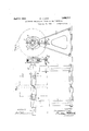
- Fig. 1 illustrates a front elevation of a paper roll which has my improved device attached thereto;
- Fig; 2 is a side elevation of Fig- 1;
- Fig; l is a sectional view taken on the line oi Fig. 3;
- FIG. 5 a similar view of Fig. 3 with a control lever just about to come into action
- Fig. 6 is a sectional View tal-Zenon the line 66 of Fig. 3,with the central shaft in full to illustrate a bayonetjoint
- Fig.1 7 shows a bottom plan view of the device depicted in 3;
- Figs. 8 and 9 are diagrammatic views to be used in the explanation ofthe operation of my improved device.
- the numeral 1' designates brackets which support a shaft 2 in the usual manner.
- a roll 3 of paper which is'maintained in proper alignment with respect to the shaft by use of the usual adjustiug cones 4.
- my improved device is mounted in any suitable manner.
- This device consists essentially of a central drum 5 about which are clamped jaws 6, 6 which are secured together or hinged at their upper end by means of aspecial hinge bolt 7 and at their lower end by a slide member 8.
- a prying arm 9 Associated with slide member 8 is a prying arm 9 which opens the jaws 6, 6.
- the prying arm 9 P jects downwardly end bracket 1.
- the function of the prying or reaction arm is to pry jaws 6, 6' apart when the shaft 2 is rotated.
- the greatest prying effect of arm 9 and the least clamping effect of jaws 6. Goccur when the roll 3 of sheet material has the largest diameter and the least prying effect and the greatest clamping efiect occur when the roll 3 has the smallest diameter.
- the relation of the size of the roll to the prying effect is of particular importance due to the fact that when the roll is largest the speed of rotation is slowest and the clamping effect of the jaws on the drum is more effective at the slow speed whereas when the roll becomes smaller the speed of rotation becomes greater and the clamping effect of the jaws on the drum is not as effective at slower speeds of rotation.
- each jaw web 12 I I On the inner face of each jaw web 12 I I provide a frictional pad or surface 21, such as well known asbestos friction lining.
- This lining is held in place by set screws 22 or thelike and is held in engagement with the outer periphery of central drum 5.
- This drum is secured to shaft 2 by means of a bayonet pin 22 projecting therefrom and fitting in slot 23- in the shaft.
- the bayonet slot 23 is provided at its innermostend with a transverse slot 24 adapted to engage bayonet pin 23 in either direction of rotation of the drum and shaft.
- Central drum 5 is preferably made with a plurality of ventilating apertures 25 which tend to cool the drum when in operation. This ventilation, of course, tends to keep the temperature of the frictional elements relatively low, and thus, prevents them from burning out.
- Jaws 6 are held in place by means of a pair of annular plates 27 fastened to each side of central drum 5. Between the outer face of central drum 5 and the inner face of plates 27 w ood-oilless washers 28' which are interposed to minimize the friction between the moving plates 27 and the outer faces 29 of stationary aws 6.
- These wood-oilless washers as is well known, provide excellent lubricat-ion for the partswith which they are in contact without the necessity of receiving any extraneous lubricating agent. In practice I have found that the wood-oilless Washers may be used for long periods of time before renewing them.
- Shaft 2 supporting a roll of paper 3 is positioned on brackets l in such a manner that the right hand end of the shaft projects beyond bearing 30 of the right hand bracket.
- the right hand end of the projecting shaft is provided with bayonet slot 22 as described before so that my device may readily and quickly be mounted on the shaft by sliding bayonet pin 22 in bayonet slot 23 and the internal bore 31 of central drum 5 on shaft 2.
- Stop bar 10 is then adjusted so that when the reaction bar 9 contacts with bar 10, it will be engaged between a pair of collars 32.
- Set screws 16 are adjusted to put springs 15 under the proper compression and thus clamp jaws 6 with their frictional lining 21 in contact withcentral drum 5 with a suitable friction.
- the paper is drawn from the upper side of the roll by suitable mechanism (not shown) and the roll 3 is set in rotation.
- the rotation is illustrated as being counter clockwise.
- central drum 5 is rotated therewith because ofthe bayonet joint.
- the rotation of central drum 5 causes a frictional grip on lining 21 and thereby gives the tension control device a tendency to rotate as a whole unit.
- reaction bar 9 comes into contact with stop bar 10 which prevents any further rotation of the clamping jaws and associated parts. This causes a certain frictional drag on the shaft so as to put the web of paper leaving the roll under a certain tension.
- springs 15 any desired or predetermined tension maybe established in the sheet material.
- Fig. 8 the roll is depicted as being approximately full size so that there is a leverage arm between the center of the shaft and the periphery of the roll of say about three feet.
- This relatively large leverage arm causes a corresponding large reaction pressure on reaction bar 9 which is in engagement with stop bar 10.
- the reaction bar being subject to this relatively large reaction pressure tends, via slide member 8, to pry apart the clamping jaws 6 against the pressure ofcompression springs 15 and, thus, decrease the raq friction existing between lining 21 and the periphery face of central drum 5' so that there is only a relatively small frictional drag ex ist-lng at the start of the operation or run.
- the over-all effect of springs is not affected by movement of slide member 8 because as one spring becomes shorter the second becomes larger, and, thus, compensates for changes in the first spring.
- my invention provides a device for automatically controlling a web of sheet material being unwound from a roll and that my improved device is provided with a construction wherein the clamping jaws are not opened by the direct action of the prying bar 011 a face plate at the end of one of the jaws but by the indirect action of the prying bar on the slide which coacts with one of the pins 14 to effect closing of the clamping jaws.
- my improved device is provided with a construction wherein the clamping jaws are not opened by the direct action of the prying bar 011 a face plate at the end of one of the jaws but by the indirect action of the prying bar on the slide which coacts with one of the pins 14 to effect closing of the clamping jaws.
- my inven tion provides a device of the character herein set forth which eliminates slackness in the web of sheet material between the point where it is drawn off the roll and the point where it is used even when the roll slows down and stops because the clamping of the jaws on the drum becomes more eflective as the roll rotates. slower and the overall frictional drag keeps in step. with the decreasing speed of the roll to preserve a taut condition in the sheet material and to prevent any substantial. slackness therein.
- a device for controll-ing the tension in sheet material leaving a roll of such material which comprises a hollow drum provided with ventilating apertures, means associated with said drum for securingit to a shaft, a pair of metal jaw-s surrounding said drum and having internal webs adjacent the periphery of said drum, frictional lining secured to each of said webs for hearing against the periphery of said drum, lugs positioned atone end of said jaws, a hinge bolt operatively associated with said lugs for holding the jaws together at.
- a device for controlling the tension in sheet material leaving a roll of such material which comprises a hollow metal drum provided with ventilating apertures, means associated with said drum for securing it to a shaft, a pair of opposed, mating metal j aws. surrounding said drum and having internal webs.
- the combination comprising a shaft adapted to carry a roll of sheet material, a pair of brackets supporting said shaft, a stop bolt secured to and projecting from the side of one of said brackets, and a reaction braking device for automatically controlling the contact with said drum, and a reaction bar associated with said slide member and adapted to contact with said stop'bolt and to pry said jaws apart whereby the clamping contact on said drum is decreased.
- the combination comprising a shaft adapted to carry a roll of sheet material, a pair of brackets supporting said shaft, a stop bolt secured to and projecting from the side of one of said brackets, and a reaction braking device for automatically controlling the tension in the sheet material leaving the aforesaid roll of such sheet material which comprises a central drum, a bayonet pin projecting from the interior of said drum and adapted to engage a bayonet slot in a shaft carrying a roll of sheet material, a pair of clamping jaws fitted around said drum, a hinge member at one end of said jaws to secure them together, a slide member positioned at the other end of said jaws to hold them in resilient compression, and a reaction bar pivotally mounted on said slide member and adapted to contact with said bolt and to engage an adjacent end of one of said jaws to pry the jaws apart.
- the combination comprising a shaft adapted to carry a roll of sheet material, a pair of brackets supporting said shaft, a stop bolt secured to and projecting from the side of one of said brackets, and a reaction braking device for automatically controlling the tension in the sheet material leaving the aforesaid roll of such sheet material which comprises a hollow drum provided withventilating apertures, means associated with said drum for securing it to a shaft, a pair of metal'jaws surrounding said drum and having internal webs adjacent the periphery of said drum, frictional lining secured to each of said webs for bearing against the periphery of said drum, lugs positioned at one end of said jaws, a hinge bolt operatlvely associated with said lugs for holding the jaws together at one end, slots provided in s'aidjaws at the other end thereof, a pin secured in each slot, a slide member fitting in said slots and cooperating with said pins,
- the combination comprising a shaft adapted to carry a roll of sheet material, a-
- a reaction braking device for automatically controlling the ten sion inthe sheet mater1al leaving the aforesaid roll of such sheet material
- a hollow' metal drum provided withventilating apertures, means associated with said drum for securing it to a shaft, a pair of opposed, mating metal'jaws surrounding said drum and having internal webs-adj acent the periphery of said drum, frictional lining 'securedto each of said webs for bearing against the periphery of sa1d drum, lugs positioned at one end of said jaws, an adjustable hinge bolt operatively associated with said lugs for holding the jaws together atone end, slots provided in said jaws at the other end thereof, a pin secured in each slot, a slide member fitting in said slots and cooperating with said pins, adjustable resilient meansassociated with said slide member for bearing against said pins and clamping the a
- the combination comprising a shaft jaws at their ends opposite to the hinged portion and resiliently clamping the jaws in contact with said drum, a reaction bar associated with said slide member and adapted to contact with said stop bolt and to pry said jaws apart whereby the clamping contact onsaid drum is decreased, a pair of retaining plates secured to the sides of said jaws to hold them in position around the drum and wooden oilless washers interposed between said retaining plates and the face of contiguous aws.
- the combination comprising a shaft adaptedto carry a roll of sheet material, a pair of brackets supporting said shaft, a stop bolt secured to and projecting from the side of one of said brackets, and a reaction braking device which comprises a pair of opposed mating jaws resiliently clamped about a drum which is mounted on a projecting end of said shaft and a reaction bar associated with said jaws and adapted to engage the stop bar on V the bracket adjacent to the projecting end of the shaft when the shaft and roll thereon is rotated so as to pry the jaws apart with a force which is proportional to the distance between the periphery of the roll of sheet material to the center of the shaft.
Landscapes
- Unwinding Webs (AREA)
- Winding Of Webs (AREA)
Description
F. J. LANZ 1,852,317
DEVICE FOR CONTROLLING TENSION IN SHEET MATERIAL April 5, 1932.
Filed May 29, 1929 3 Sheets-Sheet 11v VEN TOR F/PEDfR/C/K d L A i/Z A TTORNE VS WITNESS fiwp April 5, 1932. F J. LANZ 1,352,317
DEVICE FOR CONTROLLING TENSION IN SHEET MATERIAL Filed May 29, 1929 3 Sheets-Sheet 2 A TTORNE Y8 H A Nb w UN .0.
WITNESS %7 April 5, 1932; F. J..'LANZ DEVICE FOR CONTROLLING 'IjENSION IN SHEET MATERIAL Filed May 29, 1929 3 Sheets-Sheet 3 INVENTOR WITNESS g I BOY I A TTOR/VE Y5 Patented Apr. 5, 1932 UNITED STATES PATENT OFFICE;
FREDERICK J LANE, OF NEW YORK, N. Y., CORPORATION, 035 NEW YORK, N.
trollin tension in sheet material, and more a 1 u particularly to devices capable oi being applied to rolls containing sheet material, such as paper.
A general object of this invention is to provide a device which will overcome the objectionsand defcctsof prior devices.
A further objectof the invention is to pro vide a tension controlling device which is readily and quickly detachable from a shaft and which is capable of easy and quick application to a shaft.
The invention also contemplatesthe pro vision of a device which is simple in construction, which is easy to use and which is adjustable.
A further featureo'f the invention is to provide a device of the character set forth which unitary in character and which is practically self contained.
Other objects and features of the invention willbccome apparent from the following description taken in conjunction with the accompanying drawings, in which:
Fig. 1 illustrates a front elevation of a paper roll which has my improved device attached thereto;
Fig; 2 is a side elevation of Fig- 1;
Fig. 3de'pict-s a side View of my improved device, partly in the section for the purpose of clarity;
Fig; l is a sectional view taken on the line oi Fig. 3;
Fig; 5 a similar view of Fig. 3 with a control lever just about to come into action Fig. 6 is a sectional View tal-Zenon the line 66 of Fig. 3,with the central shaft in full to illustrate a bayonetjoint Fig.1 7 shows a bottom plan view of the device depicted in 3; and
Figs. 8 and 9 are diagrammatic views to be used in the explanation ofthe operation of my improved device.
Although my improved device for automatically controlling the tension in sheet Inaterial as it leaves the roll in applicable to manyindustries which will be described here in with particularreference to the paper industry. It is to be noted, however; that my ASSIGNOR' TO GONTINENTAL RAPER-80 BAG Y., A CORPORATEON 0F DEL-AWARE TENSION IN SHEET MATERIAL 1929. Serial No. 366,848.
invention isnot limited to the paper industry,
but only by the scope of thepending claims.
Referring more particularly to Figs. land 2, the numeral 1' designates brackets which support a shaft 2 in the usual manner. Mounted upon the shaft 2 is a roll 3 of paper which is'maintained in proper alignment with respect to the shaft by use of the usual adjustiug cones 4. On the right end of the shaft my improved device is mounted in any suitable manner. This device consists essentially of a central drum 5 about which are clamped jaws 6, 6 which are secured together or hinged at their upper end by means of aspecial hinge bolt 7 and at their lower end by a slide member 8. Associated with slide member 8 is a prying arm 9 which opens the jaws 6, 6.
The prying arm 9 P jects downwardly end bracket 1. The function of the prying or reaction arm is to pry jaws 6, 6' apart when the shaft 2 is rotated. The greatest prying effect of arm 9 and the least clamping effect of jaws 6., Goccur when the roll 3 of sheet material has the largest diameter and the least prying effect and the greatest clamping efiect occur when the roll 3 has the smallest diameter. The relation of the size of the roll to the prying effect is of particular importance due to the fact that when the roll is largest the speed of rotation is slowest and the clamping effect of the jaws on the drum is more effective at the slow speed whereas when the roll becomes smaller the speed of rotation becomes greater and the clamping effect of the jaws on the drum is not as effective at slower speeds of rotation. This means that at slow speeds of rotation when the roll is" large the prying eiiect must be greatest in order to open the jaws and to de crease the over-all clamping on the drum and that at high speeds of rotation when the roll is small the prying effect must be least inmembers having side projecting ribs 11 and an inner transverse web 12. At the top of each jaw an appropriate lug 7 is provided for the reception of bolt 7. A slot 13 is provided near the lower end of each member I member 8 via pin 17 either to the left or to the right depending upon the direction of rotation of roll 3. In the drawings (see Fig. the slide member is shown as being moved by bar 9 to the right. When this movement occurs roll 18, which is mounted directly below pin 17 on bar 9, engages hardiface plate 19 which is secured to the inner end of the bottom of jaw 6. Face plate 19 may be secured to jaw 6 by any appro riate means such as set screws 20.
On the inner face of each jaw web 12 I I provide a frictional pad or surface 21, such as well known asbestos friction lining. This lining is held in place by set screws 22 or thelike and is held in engagement with the outer periphery of central drum 5. This drum is secured to shaft 2 by means of a bayonet pin 22 projecting therefrom and fitting in slot 23- in the shaft. The bayonet slot 23 is provided at its innermostend with a transverse slot 24 adapted to engage bayonet pin 23 in either direction of rotation of the drum and shaft. Central drum 5 is preferably made with a plurality of ventilating apertures 25 which tend to cool the drum when in operation. This ventilation, of course, tends to keep the temperature of the frictional elements relatively low, and thus, prevents them from burning out.
After my device has been used for awhile the frictional lining wears away so that an appropriate adjustment must be made to maintain the proper friction on the central drum. This adjustment is effected by turning locknuts 26 on the ends of bolt 7 over pivot plates 27 so as to bring the two aws 6-6 closer together and, thus, reestablish the proper frictional contact between lining 21 and central drum 5. It should be noted, however, that this adjustment ordinarily does not have to be made very frequently.
The operation of my improved tension controlling device is simple and will be readily apparent to those skilled in the art. Shaft 2 supporting a roll of paper 3 is positioned on brackets l in such a manner that the right hand end of the shaft projects beyond bearing 30 of the right hand bracket. The right hand end of the projecting shaft is provided with bayonet slot 22 as described before so that my device may readily and quickly be mounted on the shaft by sliding bayonet pin 22 in bayonet slot 23 and the internal bore 31 of central drum 5 on shaft 2. Stop bar 10 is then adjusted so that when the reaction bar 9 contacts with bar 10, it will be engaged between a pair of collars 32. Set screws 16 are adjusted to put springs 15 under the proper compression and thus clamp jaws 6 with their frictional lining 21 in contact withcentral drum 5 with a suitable friction. The paper is drawn from the upper side of the roll by suitable mechanism (not shown) and the roll 3 is set in rotation. In the present case the rotation is illustrated as being counter clockwise. As the roll 3 and shaft 2 rotate, central drum 5 is rotated therewith because ofthe bayonet joint. The rotation of central drum 5 causes a frictional grip on lining 21 and thereby gives the tension control device a tendency to rotate as a whole unit. Asthe device rotates reaction bar 9 comes into contact with stop bar 10 which prevents any further rotation of the clamping jaws and associated parts. This causes a certain frictional drag on the shaft so as to put the web of paper leaving the roll under a certain tension. By the proper initial adjustment of springs 15 any desired or predetermined tension maybe established in the sheet material.
In Fig. 8 the roll is depicted as being approximately full size so that there is a leverage arm between the center of the shaft and the periphery of the roll of say about three feet. This relatively large leverage arm causes a corresponding large reaction pressure on reaction bar 9 which is in engagement with stop bar 10. The reaction bar being subject to this relatively large reaction pressure tends, via slide member 8, to pry apart the clamping jaws 6 against the pressure ofcompression springs 15 and, thus, decrease the raq friction existing between lining 21 and the periphery face of central drum 5' so that there is only a relatively small frictional drag ex ist-lng at the start of the operation or run. It should be noted that the over-all effect of springs is not affected by movement of slide member 8 because as one spring becomes shorter the second becomes larger, and, thus, compensates for changes in the first spring.
In Fig. 9, however, the roll has become very much smaller so that the leverage arm between the center of the shaft and the periphery of the roll is decreased. This causes a corresponding decrease in the reaction pressure on the reaction bar 9 with 2. correspond ing decrease in the prying effect upon the clamping jaws 6. The jaws. are thus pressed together by springs 15, 15 in the slide member 8 to a greater degree and consequently bring about an increase of friction between the lining 21 and the peripheral face of central drum 5.
It will be observed that my invention provides a device for automatically controlling a web of sheet material being unwound from a roll and that my improved device is provided with a construction wherein the clamping jaws are not opened by the direct action of the prying bar 011 a face plate at the end of one of the jaws but by the indirect action of the prying bar on the slide which coacts with one of the pins 14 to effect closing of the clamping jaws. By the utilization of this construction considerable wear of the friction. lining on the clamping jaws can occur before adjustment of bolt 7 is necessary. In fact the space or clearance between face plates. 19 and the roll 18 on the pryingbar can be reduced very materially without afr footing the functioning of my device.
It will also be noted that my inven tion. provides a device of the character herein set forth which eliminates slackness in the web of sheet material between the point where it is drawn off the roll and the point where it is used even when the roll slows down and stops because the clamping of the jaws on the drum becomes more eflective as the roll rotates. slower and the overall frictional drag keeps in step. with the decreasing speed of the roll to preserve a taut condition in the sheet material and to prevent any substantial. slackness therein.
Although I have described a specific embodiment of my invention, it is to be understood that the invention is not restricted to such particular embodiment. Various modifications thereof in detail and in the arrangement of the parts may be made by those skilled in the art without departing from the invention as defined in the claims.
I claim:
I. A device for controll-ing the tension in sheet material leaving a roll of such material which comprises a hollow drum provided with ventilating apertures, means associated with said drum for securingit to a shaft, a pair of metal jaw-s surrounding said drum and having internal webs adjacent the periphery of said drum, frictional lining secured to each of said webs for hearing against the periphery of said drum, lugs positioned atone end of said jaws, a hinge bolt operatively associated with said lugs for holding the jaws together at. one end, slots provided in said jaws at the other end thereof, a pin secured in each slot, a slide member fitting in said slots and cooperating with said pins, resilient means associated with said slide, member for hearing against said pins and clamping the jaws together so as tobring the frictional lining in contact with the peripheral face of the drum, and a prying bar pivotally mounted at the middle of said slide, member between said two jaws and adapted to engage one of the projecting ends of said jaws and to pry the jaws apart against said resilient means whereby the grip of said fric tional lining is decreased.
2. A device for controlling the tension in sheet material leaving a roll of such material which comprises a hollow metal drum provided with ventilating apertures, means associated with said drum for securing it to a shaft, a pair of opposed, mating metal j aws. surrounding said drum and having internal webs. adjacent the periphery of said drum, frictional lining secured to each of said webs for hearing against the periphery of said drum, lugs positioned at one end of said jaws, an adjustable hinge bolt operati-vely associated with said lugs for holding the jaws to gether at one end, slots provided in said jaws at the other end thereof, a pin secured in each slot, a slide member fitting in said slots and cooperating with said pins, adjustable resilient means associated with said slide member for bearing against said pins and clamping the jaws together so as to bring the frictional liningin contact withthe peripheral face of the drum, and a prying bar pivotally mounted at the middle of said slide member between said two jaws and having a roll which is adapted to engage oneof the pro jecting ends of said jaws and topry the jaws apart against said resilient means whereby the grip of said frictional lining is decreased.
3. The combination comprising a shaft adapted to carry a roll of sheet material, a pair of brackets supporting said shaft, a stop bolt secured to and projecting from the side of one of said brackets, and a reaction braking device for automatically controlling the contact with said drum, and a reaction bar associated with said slide member and adapted to contact with said stop'bolt and to pry said jaws apart whereby the clamping contact on said drum is decreased.
4. The combination comprising a shaft adapted to carry a roll of sheet material, a pair of brackets supporting said shaft, a stop bolt secured to and projecting from the side of one of said brackets, and a reaction braking device for automatically controlling the tension in the sheet material leaving the aforesaid roll of such sheet materialwhich comprises a central drum, a bayonet pin projecting from the interior of said drum and adapted to engage a bayonet slot in a shaft carrying a roll of sheet material, a pair of clamping jaws fitted around said drum, a hinge member at one end of said jaws to secure them together, a slide member positioned at the other end of said jaws to hold them in resilient compression, and a reaction bar pivotally mounted on said slide member and adapted to contact with said bolt and to engage an adjacent end of one of said jaws to pry the jaws apart.
5. The combination comprising a shaft adapted to carry a roll of sheet material, a pair of brackets supporting said shaft, a stop bolt secured to and projecting from the side of one of said brackets, and a reaction braking device for automatically controlling the tension in the sheet material leaving the aforesaid roll of such sheet material which comprises a hollow drum provided withventilating apertures, means associated with said drum for securing it to a shaft, a pair of metal'jaws surrounding said drum and having internal webs adjacent the periphery of said drum, frictional lining secured to each of said webs for bearing against the periphery of said drum, lugs positioned at one end of said jaws, a hinge bolt operatlvely associated with said lugs for holding the jaws together at one end, slots provided in s'aidjaws at the other end thereof, a pin secured in each slot, a slide member fitting in said slots and cooperating with said pins,
resilient means associated with said slide member for bearing against said pins and clamping the jaws together so as to bring the frictional lining in contact with the peripheral face of the drum, and a prying bar pivotally mounted at the middle of said slide member between said two jaws and adapted to contact with said bolt and to engage one of the projecting ends of said jaws and to pry the jaws apart against said resilient means whereby the grip of said frictional lining is decreased.
6. The combination comprising a shaft adapted to carry a roll of sheet material, a-
pair of brackets supporting said shaft, a stop bolt secured to and projecting from the side of one of said'brackets, and a reaction braking device for automatically controlling the ten sion inthe sheet mater1al leaving the aforesaid roll of such sheet material which comprises a hollow' metal drum provided withventilating apertures, means associated with said drum for securing it to a shaft, a pair of opposed, mating metal'jaws surrounding said drum and having internal webs-adj acent the periphery of said drum, frictional lining 'securedto each of said webs for bearing against the periphery of sa1d drum, lugs positioned at one end of said jaws, an adjustable hinge bolt operatively associated with said lugs for holding the jaws together atone end, slots provided in said jaws at the other end thereof, a pin secured in each slot, a slide member fitting in said slots and cooperating with said pins, adjustable resilient meansassociated with said slide member for bearing against said pins and clamping the aws'together so as "to bring the frictional lining in contact with the peripheral face of the drum,and a prying bar 'pivotally mounted at the middle of said slide member between said two jaws and having a roll which is adapted to engage one of the projecting ends of said jaws and to pry the jaws apart against said resilient means when the free end of the bar contacts with and pushes against said stop bolt, whereby the grip of said frictional lining is decreased.
7. The combination comprising a shaft jaws at their ends opposite to the hinged portion and resiliently clamping the jaws in contact with said drum,a reaction bar associated with said slide member and adapted to contact with said stop bolt and to pry said jaws apart whereby the clamping contact onsaid drum is decreased, a pair of retaining plates secured to the sides of said jaws to hold them in position around the drum and wooden oilless washers interposed between said retaining plates and the face of contiguous aws.
8. The combination comprising a shaft adaptedto carry a roll of sheet material, a pair of brackets supporting said shaft, a stop bolt secured to and projecting from the side of one of said brackets, and a reaction braking device which comprises a pair of opposed mating jaws resiliently clamped about a drum which is mounted on a projecting end of said shaft and a reaction bar associated with said jaws and adapted to engage the stop bar on V the bracket adjacent to the projecting end of the shaft when the shaft and roll thereon is rotated so as to pry the jaws apart with a force which is proportional to the distance between the periphery of the roll of sheet material to the center of the shaft.
In testimony whereof, I have hereunto set my hand.
FREDERICK J. LANZ.
Priority Applications (1)
| Application Number | Priority Date | Filing Date | Title |
|---|---|---|---|
| US366848A US1852317A (en) | 1929-05-29 | 1929-05-29 | Device for controlling tension in sheet material |
Applications Claiming Priority (1)
| Application Number | Priority Date | Filing Date | Title |
|---|---|---|---|
| US366848A US1852317A (en) | 1929-05-29 | 1929-05-29 | Device for controlling tension in sheet material |
Publications (1)
| Publication Number | Publication Date |
|---|---|
| US1852317A true US1852317A (en) | 1932-04-05 |
Family
ID=23444818
Family Applications (1)
| Application Number | Title | Priority Date | Filing Date |
|---|---|---|---|
| US366848A Expired - Lifetime US1852317A (en) | 1929-05-29 | 1929-05-29 | Device for controlling tension in sheet material |
Country Status (1)
| Country | Link |
|---|---|
| US (1) | US1852317A (en) |
Cited By (2)
| Publication number | Priority date | Publication date | Assignee | Title |
|---|---|---|---|---|
| US4079827A (en) * | 1974-12-30 | 1978-03-21 | Xerox Corporation | Web tension control |
| FR2510085A1 (en) * | 1981-07-27 | 1983-01-28 | Sireix Georges | Reeling machine for feeding fibrous strips to tube-maker - aligns with axis parallel to axis of tube maker, and reloads without stopping |
-
1929
- 1929-05-29 US US366848A patent/US1852317A/en not_active Expired - Lifetime
Cited By (2)
| Publication number | Priority date | Publication date | Assignee | Title |
|---|---|---|---|---|
| US4079827A (en) * | 1974-12-30 | 1978-03-21 | Xerox Corporation | Web tension control |
| FR2510085A1 (en) * | 1981-07-27 | 1983-01-28 | Sireix Georges | Reeling machine for feeding fibrous strips to tube-maker - aligns with axis parallel to axis of tube maker, and reloads without stopping |
Similar Documents
| Publication | Publication Date | Title |
|---|---|---|
| US2348162A (en) | Web spreader | |
| US1852317A (en) | Device for controlling tension in sheet material | |
| US2475476A (en) | Rubbing shoe | |
| US1395830A (en) | Automatic tension-controlling mechanism | |
| US1958152A (en) | Device for automatically adjusting the size of the loop in cinematographic apparatus | |
| US1708344A (en) | Tension control | |
| US2284314A (en) | Clamp | |
| US2364201A (en) | Web-tension equipment | |
| US2130857A (en) | Brake | |
| US1123786A (en) | Automatic brake. | |
| US2226090A (en) | Cloth roll drive | |
| US2987144A (en) | Brake for door track roller | |
| US1399988A (en) | Automatically-adjustable tensioning device | |
| US1063263A (en) | Tension-regulating device for web-presses. | |
| US1619039A (en) | Brake | |
| US1199872A (en) | Balancing device for brake-heads. | |
| US2838252A (en) | Web tension control | |
| US2065679A (en) | Brake | |
| US1157457A (en) | Paper-reel brake. | |
| US1877687A (en) | Ironing machine | |
| US2205439A (en) | Brake shoe mounting | |
| US1989092A (en) | Brake operating mechanism | |
| US2202841A (en) | Braking mechanism | |
| US1925286A (en) | Brake | |
| US1745545A (en) | Friction hinge |