US1852297A - Bolt anchor - Google Patents
Bolt anchor Download PDFInfo
- Publication number
- US1852297A US1852297A US565484A US56548431A US1852297A US 1852297 A US1852297 A US 1852297A US 565484 A US565484 A US 565484A US 56548431 A US56548431 A US 56548431A US 1852297 A US1852297 A US 1852297A
- Authority
- US
- United States
- Prior art keywords
- bolt
- metal
- anchor
- bolt anchor
- collapsible
- Prior art date
- Legal status (The legal status is an assumption and is not a legal conclusion. Google has not performed a legal analysis and makes no representation as to the accuracy of the status listed.)
- Expired - Lifetime
Links
- 229910052751 metal Inorganic materials 0.000 description 38
- 239000002184 metal Substances 0.000 description 38
- XEEYBQQBJWHFJM-UHFFFAOYSA-N Iron Chemical compound [Fe] XEEYBQQBJWHFJM-UHFFFAOYSA-N 0.000 description 16
- 230000002441 reversible effect Effects 0.000 description 11
- 238000010276 construction Methods 0.000 description 10
- 229910052782 aluminium Inorganic materials 0.000 description 9
- XAGFODPZIPBFFR-UHFFFAOYSA-N aluminium Chemical compound [Al] XAGFODPZIPBFFR-UHFFFAOYSA-N 0.000 description 9
- 229910052742 iron Inorganic materials 0.000 description 8
- 239000004567 concrete Substances 0.000 description 4
- 239000000463 material Substances 0.000 description 4
- 229910000831 Steel Inorganic materials 0.000 description 3
- 230000006835 compression Effects 0.000 description 3
- 238000007906 compression Methods 0.000 description 3
- 239000010959 steel Substances 0.000 description 3
- CWYNVVGOOAEACU-UHFFFAOYSA-N Fe2+ Chemical compound [Fe+2] CWYNVVGOOAEACU-UHFFFAOYSA-N 0.000 description 2
- 229910001296 Malleable iron Inorganic materials 0.000 description 2
- 239000011449 brick Substances 0.000 description 2
- 150000002739 metals Chemical class 0.000 description 2
- 238000000034 method Methods 0.000 description 2
- 241000543381 Cliftonia monophylla Species 0.000 description 1
- 238000004873 anchoring Methods 0.000 description 1
- 230000004048 modification Effects 0.000 description 1
- 238000012986 modification Methods 0.000 description 1
- 238000007789 sealing Methods 0.000 description 1
- 238000000926 separation method Methods 0.000 description 1
- 239000004575 stone Substances 0.000 description 1
Images
Classifications
-
- F—MECHANICAL ENGINEERING; LIGHTING; HEATING; WEAPONS; BLASTING
- F16—ENGINEERING ELEMENTS AND UNITS; GENERAL MEASURES FOR PRODUCING AND MAINTAINING EFFECTIVE FUNCTIONING OF MACHINES OR INSTALLATIONS; THERMAL INSULATION IN GENERAL
- F16B—DEVICES FOR FASTENING OR SECURING CONSTRUCTIONAL ELEMENTS OR MACHINE PARTS TOGETHER, e.g. NAILS, BOLTS, CIRCLIPS, CLAMPS, CLIPS OR WEDGES; JOINTS OR JOINTING
- F16B13/00—Dowels or other devices fastened in walls or the like by inserting them in holes made therein for that purpose
- F16B13/04—Dowels or other devices fastened in walls or the like by inserting them in holes made therein for that purpose with parts gripping in the hole or behind the reverse side of the wall after inserting from the front
- F16B13/06—Dowels or other devices fastened in walls or the like by inserting them in holes made therein for that purpose with parts gripping in the hole or behind the reverse side of the wall after inserting from the front combined with expanding sleeve
- F16B13/061—Dowels or other devices fastened in walls or the like by inserting them in holes made therein for that purpose with parts gripping in the hole or behind the reverse side of the wall after inserting from the front combined with expanding sleeve of the buckling type
-
- F—MECHANICAL ENGINEERING; LIGHTING; HEATING; WEAPONS; BLASTING
- F16—ENGINEERING ELEMENTS AND UNITS; GENERAL MEASURES FOR PRODUCING AND MAINTAINING EFFECTIVE FUNCTIONING OF MACHINES OR INSTALLATIONS; THERMAL INSULATION IN GENERAL
- F16B—DEVICES FOR FASTENING OR SECURING CONSTRUCTIONAL ELEMENTS OR MACHINE PARTS TOGETHER, e.g. NAILS, BOLTS, CIRCLIPS, CLAMPS, CLIPS OR WEDGES; JOINTS OR JOINTING
- F16B13/00—Dowels or other devices fastened in walls or the like by inserting them in holes made therein for that purpose
- F16B13/04—Dowels or other devices fastened in walls or the like by inserting them in holes made therein for that purpose with parts gripping in the hole or behind the reverse side of the wall after inserting from the front
- F16B13/08—Dowels or other devices fastened in walls or the like by inserting them in holes made therein for that purpose with parts gripping in the hole or behind the reverse side of the wall after inserting from the front with separate or non-separate gripping parts moved into their final position in relation to the body of the device without further manual operation
- F16B13/0841—Dowels or other devices fastened in walls or the like by inserting them in holes made therein for that purpose with parts gripping in the hole or behind the reverse side of the wall after inserting from the front with separate or non-separate gripping parts moved into their final position in relation to the body of the device without further manual operation with a deformable sleeve member driven against the abutting surface of the head of the bolt or of a plug
Definitions
- This invention relates to means for fastening fixtures of various designs to brick, concrete, or other masonry.
- Another object of my invention is to provide a bolt anchor which, because of its design, insures that it will always be used in the proper manner. 7
- Another object of my invention is to provide a unitary,reversible bolt anchor which is light, yet possesses great strength, and one which can be economically manufactured.
- Figure 1 is an elevation of my reversible, unitary bolt anchor.
- Figure 2 is an end view of Figure 1.
- Figure 3 is a part-sectional view through a section of concrete, showing the bolt and bolt anchor in position before caulking operations are performed.
- Figure 4 is a view similar to Figure 3, but after the caulking operation has been performed. s
- Figure 5 is a part-elevational and partsectional view.-similar to Figure 1, but showing a modified form of construction of the central portion of the bolt anchor.
- Figure 6 is a fragmentary view of the central part of the bolt anchor, showing a still further modified form of the central construction.
- Fi re 7 is a view similar to Figure 6, showing a still further modified construction.
- Figure 8 is a part-sectional view of another application of my invention.
- Figure 9 is a view of another modified form of bolt anchor.
- FIG. 10 shows a still further modification.
- the boltanchor is composed of a metallic member 1 having end flanges-2 and 3.
- the two rigid end portions adjacent the flanges 2 and 3. are conical'ly-shaped and the cones or frustums terminate in a central annular section 4 which is relatively thin, whereby this portion is readily collapsible for the purpose to be hereinafter referred to.
- the metallic member 1 is made of a metal that is both malleable and ductile. I have found that aluminum, possessing both of these qualities, and also being light, is very satisfactory for the construction of this metallic member. It is to be understood, however, that I am not limited to the use of aluminum for this member.
- the lead Surrounding the central portion 4 of the member 1, and preferably extending from the flange 2 to the flange 3, is another member 5 of readily expansible metal such as lead, and in the preerred form of construction, the lead is moulded around the member 1 after the same has been constructed as above described.
- the diameter oftthe expansible member 5 is the same diameter as the flanges 2 and 3, so that after the member 5 has been moulded or placed in position as indicated, a complete, unitary, cylindrically-shaped anchor member is obtained as shown in, Figure 1.1 Whilethe central portion 4, whioh joinsthe two rigid cone-shaped portions, maybe of uniform thickness, but relatively thin, whereby force in the shape of blows applied to one of the flanges will readily'collapse the central portion 4, this collapsibility' may be enhanced by providing the cylindricallyshaped portion 4 with a plurality of slots 6 as shown in Figure 5. or by a plurality of holes? as shown in Figure ,6, or by a shallow annular groove 8 as indicated in Fi Either one, or acombination or equlvalent of these modified constructions may be used into the hole about as indicated in Figure 3.
- the bolt anchor may be applied to the bolt and then the two inserted into the hole 10, but in either case, as soon as they are inserted, as shown in Figure 3, the caulking operating is begun bypassing a hollow tool over the bolt 11 and applying blows thereto which are transmitted to the flange 2. This operation causes the cones 1 and 2 to be compressed together, thereby collapsing the central portion 4 and expanding the soft metal of thermember 5 into engagement with the wallfof the hole 10.
- the member 1 is more rigid than-the member 5 and acts as a collar for holding the expanded soft metal in this expanded position without creeping or flowing upward or downward in.the hole.
- a ductile metal such as aluminum
- the metal is soft enough to expand the full width of the hole when the caulking operation is performed, thereby sealing the expanded soft metal within its own caulked length as already described, at the same time being sufli'ciently rigidto hold this softer metal permanently against slipping or loosening by vibration.
- a ductile metal such as aluminum in combination with a soft mouldable metal such as lead, insures a complete compression and expansion of the entire unit as a homogeneous mass instead of an uneven expansion of the soft metal, or a separation of the two metals when the hard metal is not ductile such as iron.
- the aluminum insures'a maxi- -mum compression ofthe whole unit even in a larger diameter hole where further spreading is required; whereas, iron prevents any further expansion by compression than the actual height of the iron itself.
- the head 12 of the bolt 11' is forced into the flange 3 as indicated at 13.
- the head 12 of the bolt is preferably polygonal in shape, the forcingof the head 12 into the flange 3 will prevent the bolt from turning within the hole, and the gripping of both the flanges 2 and 3 with the-member 5 on to the sides of the hole, produces a highly effective anchorage.
- the unitary bolt anchorjust described may be placed on the bolt 11 or dropped into the hole 10 without any regard as to which end is down or which end is up. i
- the ordinary workman is apt to forget which part should go in first; or where a number of these parts are used, following the usual caulking operation'on two of them, the workman is quite apt to forget the sequence in which he put the various parts into the hole over the bolt.
- My construction absolutely obviates this great disadvantage of separable bolt anchors.
- part 1 in addition, by making part 1 out of aluminum, I obtain lightness combined with strength, and the lightness of these devices is quite an important item in shipping and carrying them in tool bags or pockets of the workman. The workman does not have to remember anything but to take one of the reversible unitar anchors out of his pocket or tool bag and rop itinto the hole or over the bolt.
- the lower art of the metallic member 1 may be threa ed to receive a threaded bolt or stud 14 as indicated in Figure 8.
- the'unitary bolt anchor is not fastened in the hole by the caulking operation previously described, but by the use of a dummy bolt or stud which is used during the caulking operation.
- the; lower conical portion of the member 1 is preferably provided with arecess 15 to allow chips or dirt of any kind to fall through the threaded hole out of the way into the recess 15, so that they will not'interfere with the application of the permanent bolt or stud later on.
- the metallicmember 1 is made in two parts 16 and 17, the member 17 being made of some hard material such as iron or steel.
- the member 17 is provided with an annular groove 18, and the upper portion 16,
- the construction is substantially the same as shown in Figure 9, except the member 17 is provided with a sleeve which extends upwardly Within the end adjacent the central collapsible portion 4.
- the purpose of the sleeve or collar 20 is to prevent the collapsible section 4 from filling the hole during the caulking operation, and no dummy bolt or stud is needed as in Figures 8 and 9.
- a caullring iron is used having a short extension of smaller diameter which will fit inside the sleeve 20 during the caulking operation,
- the threaded type of anchor is, of course, not reversible but must be inserted in the hole in only one Way; that is, with the threaded end toward the bottom of the hole.
- a bolt anchor comprising two rigid end portions connected by an intermediate collapsible portion, and an expansible member overlying said collapsible portion.
- a bolt anchor comprising two rigid, hollow flanged end portions connected by an integral intermediate collapsible portion, and an expansible member overlying said collapsible portion and extending between said flanges.
- a bolt anchor comprising two rigid hollow cone-shaped end portions connected at a distance fromtheir respective bases by a collapsible portion, andan expansible member overlying said collapsible portion.
- a bolt anchor comprisinga spool-shaped member of ductile metal, said spool "being tilled with readily expansible metal, and the spool at its central portion being collapsible as and for the purpose described.
- a bolt anchor comprising a spool-shaped member of ductile metal, said spool carrying, at least around its central portion, readily erpansible metal, and the spool at its central 7.
- a unitary article of commerce compris- A ing a bolt anchor including a spool-shaped member having its central portion collapsible, and an expansible member permanently surrounding at least said central portion.
- a reversible unitary bolt anchor comprising a spool-shaped metallic member having its central portion constructed so as to readily collapse by force applied to a head of the spool, and an expansible member permanently surrounding the spool between said heads.
- a reversible unitary bolt anchor composed of two members, a spool-shaped metallic member of ductile material having its central portion collapsible, and a member of readily expansible metal carried on the spool between the heads thereof.
- a reversible unitary bolt anchor comprising two hollow cone-shaped metallic members having flanges at their bases which form the ends of the anchor, said members being joined by a collapsible section, and a member of readily expansible metal moulded around said cones and collapsible section between said flanges, and having a diameter approximately the same as the flanges.
- a reversible unitary bolt anchor comprising a metallic member having a central ore for a bolt and also having flanges at each end, and an intermediate collapsible portion, and expansible metal moulded around said flanged metallic member between said flanges.
- a cylindrically-shaped reversible bolt anchor comprising a member having a bore for a bolt, the central portion of said member being collapsible, and an 'expansible member surrounding at least said collapsible portion.
- a cylindrically-shaped bolt anchor comprising a member of ductile metal having a flange at least at one end, and a bore for a bolt, the central portion of said member being constructed so as to collapse, and readily expansible metal permanently positioned around at least said collapsible portion.
- a cylindrically-shaped bolt anchor comprising .a metallic member having flanges at bothrendsanda bore for a bolt, the central portion of said member being constructed so as to collapse, and readily expansible metal positioned around said'member between and of substantially the diameter of said flanges.
- said flanged. member is made of aluminum, and the said readily expansible metal is lead.
- a unitary cylindrically-shaped, reversible bolt anchor comprising a metallic member having a bore for a bolt, and expansible 1 metal surrounding said member between its extremities, said member being collapsible within the confines of said expansible metal, whereby a caulking operation on said member will expand said expansible metal for the purposes described.
- a unitary cylindrically-shaped bolt anchor comprising; a metallic structure having' a passageway therethrough, and having its central portion of smaller diameter than its end portions, and constructed so as to collapse under force, and expansible metal moulded around said reduced central portion as and for the purpose described.
- a unitary cylindrically-shaped bolt anchor including a hollow metallic structure composed of two pieces moulded together, one piece being of iron or steel and internally threaded, and the other being of softer but ductile metal, said threaded piece having a collar extending into the hollow part of the other piece, that part of which is around the collarbeing relatively thin and collapsible, and readily expansible metal moulded around said metallic structure outside said collapsible art.
Landscapes
- Engineering & Computer Science (AREA)
- General Engineering & Computer Science (AREA)
- Mechanical Engineering (AREA)
- Dowels (AREA)
- Joining Of Building Structures In Genera (AREA)
Description
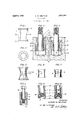
April 5, 1932. A w. GELPCKE BOLT ANCHOR Filed Sept. 28, 1951 FIG: 4
FJGIB FIG-l FIG-7 FIG: 5
FIG: 5
Patented Apr. 5, 1932 UNITED STATES PATENT OFFICE ALFRED WALTER GELIECKE, F BROOKLYN, NEW YORK, ASSIGNOR TO THE RAWLPLUG COMPANY, INC., 0]? NEW YORK, 11'. Y.
BOLT ANCHOR Application 'filed September 28, 1931. Serial No. 565,484.
This invention relates to means for fastening fixtures of various designs to brick, concrete, or other masonry.
in order to fasten such fixtures to concrete, stone, or brick structures, it is usually necessary to find some satisfactory method of setting a bolt into the surface to which anchorage is to be secured. Many methods have in the past been proposed, with varying degrees of success, for positioning or anchoring the holding bolts in such structures.
It is therefore the principal object of my invention to provide what I believe to be an entirely new form of anchorage for such holding bolts.
Another object of my invention is to provide a bolt anchor which, because of its design, insures that it will always be used in the proper manner. 7
Another object of my invention is to provide a unitary,reversible bolt anchor which is light, yet possesses great strength, and one which can be economically manufactured.
These and other objects will be clear to one skilled in the art on reading the specification taken in connection with the annexed drawings, wherein:
Figure 1 is an elevation of my reversible, unitary bolt anchor.
Figure 2 is an end view of Figure 1.
Figure 3 is a part-sectional view through a section of concrete, showing the bolt and bolt anchor in position before caulking operations are performed. '3
Figure 4 is a view similar to Figure 3, but after the caulking operation has been performed. s
Figure 5 is a part-elevational and partsectional view.-similar to Figure 1, but showing a modified form of construction of the central portion of the bolt anchor.
Figure 6 is a fragmentary view of the central part of the bolt anchor, showing a still further modified form of the central construction.
Fi re 7 is a view similar to Figure 6, showing a still further modified construction.
Figure 8 is a part-sectional view of another application of my invention.
Figure 9 is a view of another modified form of bolt anchor.
Figure 10 shows a still further modification.
Referring now to the details, wherein like numbers correspond to the parts in the VflI'i: ous views, the boltanchor is composed of a metallic member 1 having end flanges-2 and 3. The two rigid end portions adjacent the flanges 2 and 3. are conical'ly-shaped and the cones or frustums terminate in a central annular section 4 which is relatively thin, whereby this portion is readily collapsible for the purpose to be hereinafter referred to. Preferably the metallic member 1 is made of a metal that is both malleable and ductile. I have found that aluminum, possessing both of these qualities, and also being light, is very satisfactory for the construction of this metallic member. It is to be understood, however, that I am not limited to the use of aluminum for this member. Surrounding the central portion 4 of the member 1, and preferably extending from the flange 2 to the flange 3, is another member 5 of readily expansible metal such as lead, and in the preerred form of construction, the lead is moulded around the member 1 after the same has been constructed as above described.
Preferably the diameter oftthe expansible member 5 is the same diameter as the flanges 2 and 3, so that after the member 5 has been moulded or placed in position as indicated, a complete, unitary, cylindrically-shaped anchor member is obtained as shown in, Figure 1.1 Whilethe central portion 4, whioh joinsthe two rigid cone-shaped portions, maybe of uniform thickness, but relatively thin, whereby force in the shape of blows applied to one of the flanges will readily'collapse the central portion 4, this collapsibility' may be enhanced by providing the cylindricallyshaped portion 4 with a plurality of slots 6 as shown in Figure 5. or by a plurality of holes? as shown in Figure ,6, or by a shallow annular groove 8 as indicated in Fi Either one, or acombination or equlvalent of these modified constructions may be used into the hole about as indicated in Figure 3.
Of course, the bolt anchor may be applied to the bolt and then the two inserted into the hole 10, but in either case, as soon as they are inserted, as shown in Figure 3, the caulking operating is begun bypassing a hollow tool over the bolt 11 and applying blows thereto which are transmitted to the flange 2. This operation causes the cones 1 and 2 to be compressed together, thereby collapsing the central portion 4 and expanding the soft metal of thermember 5 into engagement with the wallfof the hole 10.
The member 1 is more rigid than-the member 5 and acts as a collar for holding the expanded soft metal in this expanded position without creeping or flowing upward or downward in.the hole. I have found by using a ductile metal, such as aluminum, for this member, that the metal is soft enough to expand the full width of the hole when the caulking operation is performed, thereby sealing the expanded soft metal within its own caulked length as already described, at the same time being sufli'ciently rigidto hold this softer metal permanently against slipping or loosening by vibration. The, use of a ductile metal such as aluminum in combination with a soft mouldable metal such as lead, insures a complete compression and expansion of the entire unit as a homogeneous mass instead of an uneven expansion of the soft metal, or a separation of the two metals when the hard metal is not ductile such as iron. The aluminum insures'a maxi- -mum compression ofthe whole unit even in a larger diameter hole where further spreading is required; whereas, iron prevents any further expansion by compression than the actual height of the iron itself.
In other words, in all other devices of this character of which I am aware, there is an iron member which cannot be compressed, and therefore if the hole is oversized, none of these other devices will grip the sides of the hole as the amount of the expansion is limited to the distance between the iron members. Aluminum or other ductile metals rmit complete expansion until the hole is lled, and the collars willexpand and grip the walls of the hole, thereby increasing the holding power of the unit, and will of course,
also completely seal in the lead as has been explained. The holdin power is developed by the complete unit an not only by the lead.
In addition, it will be noted from Figure 4, that the head 12 of the bolt 11' is forced into the flange 3 as indicated at 13. 'Since the head 12 of the bolt is preferably polygonal in shape, the forcingof the head 12 into the flange 3 will prevent the bolt from turning within the hole, and the gripping of both the flanges 2 and 3 with the-member 5 on to the sides of the hole, produces a highly effective anchorage.
It is to be especially noted that the unitary bolt anchorjust described may be placed on the bolt 11 or dropped into the hole 10 without any regard as to which end is down or which end is up. i This differs materially from many bolt anchors now on the market which are composed of a plurality of separate pieces, one of very hard metal such as malleable iron, and the other of a soft metal such as lead. By the use of such separate parts, the ordinary workman is apt to forget which part should go in first; or where a number of these parts are used, following the usual caulking operation'on two of them, the workman is quite apt to forget the sequence in which he put the various parts into the hole over the bolt. My construction absolutely obviates this great disadvantage of separable bolt anchors.
In addition, by making part 1 out of aluminum, I obtain lightness combined with strength, and the lightness of these devices is quite an important item in shipping and carrying them in tool bags or pockets of the workman. The workman does not have to remember anything but to take one of the reversible unitar anchors out of his pocket or tool bag and rop itinto the hole or over the bolt.
For certain classes of work where a threaded bolt or rod is required in the concrete or masonry, the lower art of the metallic member 1 may be threa ed to receive a threaded bolt or stud 14 as indicated in Figure 8. In this particular case, the'unitary bolt anchor is not fastened in the hole by the caulking operation previously described, but by the use of a dummy bolt or stud which is used during the caulking operation.
In the form shown in Figure 8, the; lower conical portion of the member 1 is preferably provided with arecess 15 to allow chips or dirt of any kind to fall through the threaded hole out of the way into the recess 15, so that they will not'interfere with the application of the permanent bolt or stud later on. I
In Figure 9, the metallicmember 1 is made in two parts 16 and 17, the member 17 being made of some hard material such as iron or steel. The member 17 is provided with an annular groove 18, and the upper portion 16,
lll
titi
til
"which is preferably made of aluminum or some other ductile metal as already described, is moulded to the member 17, a permanent loch being-secured between the two parts by reason of the annular groove 18. The member l? is provided with threads 19, and since this member may be made of malleable iron or steel, the strength of the threads is materially greater than in the construction shown.
in Figure 8. Otherwise, the/device is the same as has -been described.
lln Figure 10, the construction is substantially the same as shown in Figure 9, except the member 17 is provided with a sleeve which extends upwardly Within the end adjacent the central collapsible portion 4. The purpose of the sleeve or collar 20 is to prevent the collapsible section 4 from filling the hole during the caulking operation, and no dummy bolt or stud is needed as in Figures 8 and 9. To caulk this type of anchor, a caullring iron is used having a short extension of smaller diameter which will fit inside the sleeve 20 during the caulking operation,
lt may be further mentioned that the threaded type of anchor is, of course, not reversible but must be inserted in the hole in only one Way; that is, with the threaded end toward the bottom of the hole.
l 'rom what has been said, it will be seen "that l have provided a relatively simple and inexpensive bolt anchor which can be sold and used as a single, reversible, unitary device with all of the attending advantages as has been pointed out, and the details entering into the construction may be varied without departing from the spirit of my invention or the scope of the appended claims.
Having thus described my invention, what l claim is:
l. A bolt anchor comprising two rigid end portions connected by an intermediate collapsible portion, and an expansible member overlying said collapsible portion.
9;. A bolt anchor. comprising two rigid, hollow flanged end portions connected by an integral intermediate collapsible portion, and an expansible member overlying said collapsible portion and extending between said flanges.
3. A bolt anchor comprising two rigid hollow cone-shaped end portions connected at a distance fromtheir respective bases by a collapsible portion, andan expansible member overlying said collapsible portion.
l. A bolt anchor comprisinga spool-shaped member of ductile metal, said spool "being tilled with readily expansible metal, and the spool at its central portion being collapsible as and for the purpose described.
5. A bolt anchor comprising a spool-shaped member of ductile metal, said spool carrying, at least around its central portion, readily erpansible metal, and the spool at its central 7. A unitary article of commerce compris- A ing a bolt anchor including a spool-shaped member having its central portion collapsible, and an expansible member permanently surrounding at least said central portion.
8. A reversible unitary bolt anchor comprising a spool-shaped metallic member having its central portion constructed so as to readily collapse by force applied to a head of the spool, and an expansible member permanently surrounding the spool between said heads.
9. A reversible unitary bolt anchor composed of two members, a spool-shaped metallic member of ductile material having its central portion collapsible, and a member of readily expansible metal carried on the spool between the heads thereof.
10. A reversible unitary bolt anchor comprising two hollow cone-shaped metallic members having flanges at their bases which form the ends of the anchor, said members being joined by a collapsible section, and a member of readily expansible metal moulded around said cones and collapsible section between said flanges, and having a diameter approximately the same as the flanges.
11. A reversible unitary bolt anchor comprising a metallic member having a central ore for a bolt and also having flanges at each end, and an intermediate collapsible portion, and expansible metal moulded around said flanged metallic member between said flanges.
12. A cylindrically-shaped reversible bolt anchor comprising a member having a bore for a bolt, the central portion of said member being collapsible, and an 'expansible member surrounding at least said collapsible portion.
13. A cylindrically-shaped bolt anchor comprising a member of ductile metal having a flange at least at one end, and a bore for a bolt, the central portion of said member being constructed so as to collapse, and readily expansible metal permanently positioned around at least said collapsible portion.
7 ;-1i4. A cylindrically-shaped bolt anchor comprising .a metallic member having flanges at bothrendsanda bore for a bolt, the central portion of said member being constructed so as to collapse, and readily expansible metal positioned around said'member between and of substantially the diameter of said flanges.
15. A bolt anchor as set forth in claim 14, further characterized in that said flanges are of ductile and malleable metal whereby said flanges will also expand under the caulking operation to fill the anchor hole, grip the bolt head, and confine the said readily expan- I sible metal between said flanges substantially as described.
16. A bolt anchor as set forth in claim 14,
characterized in that said flanged. member is made of aluminum, and the said readily expansible metal is lead.
17. A bolt anchor as set 'forth in claim 14,
characterized in that the flanged member is,
of harder material than said readily expansible material.
18. A unitary cylindrically-shaped, reversible bolt anchor comprising a metallic member having a bore for a bolt, and expansible 1 metal surrounding said member between its extremities, said member being collapsible within the confines of said expansible metal, whereby a caulking operation on said member will expand said expansible metal for the purposes described.
19. A unitary cylindrically-shaped bolt anchor comprising; a metallic structure having' a passageway therethrough, and having its central portion of smaller diameter than its end portions, and constructed so as to collapse under force, and expansible metal moulded around said reduced central portion as and for the purpose described.
20. A bolt anchor as set forth in claim 19, further characterized in that one end of said bore maybe threaded for the purpose described.
21. A bolt anchor as set forth in claim 19, further characterized in that one of said end portions may be of different metal than the other end portion, and threaded for the purpose described.
22. A bolt anchor as set forth in claim 19, further characterized in that one of said end portions may be of; different metal than the other end portion and threaded, and still further characterized in that said threaded portion has a collar extending toward said other end portion, as and for the purpose described.
23. A unitary cylindrically-shaped bolt anchor including a hollow metallic structure composed of two pieces moulded together, one piece being of iron or steel and internally threaded, and the other being of softer but ductile metal, said threaded piece having a collar extending into the hollow part of the other piece, that part of which is around the collarbeing relatively thin and collapsible, and readily expansible metal moulded around said metallic structure outside said collapsible art. p 24. A bolt anchor as set forth in claim 19, further characterized in that one end portion is threaded and has a collar extending toward said other end portion as and for the purpose described.
In testimony whereof, I aflix mysignature.
ALFRED WALTER-GELPCKE.
Priority Applications (2)
| Application Number | Priority Date | Filing Date | Title |
|---|---|---|---|
| US565484A US1852297A (en) | 1931-09-28 | 1931-09-28 | Bolt anchor |
| GB26943/32A GB389752A (en) | 1931-09-28 | 1932-09-28 | Improvements in or relating to bolt anchors |
Applications Claiming Priority (1)
| Application Number | Priority Date | Filing Date | Title |
|---|---|---|---|
| US565484A US1852297A (en) | 1931-09-28 | 1931-09-28 | Bolt anchor |
Publications (1)
| Publication Number | Publication Date |
|---|---|
| US1852297A true US1852297A (en) | 1932-04-05 |
Family
ID=24258810
Family Applications (1)
| Application Number | Title | Priority Date | Filing Date |
|---|---|---|---|
| US565484A Expired - Lifetime US1852297A (en) | 1931-09-28 | 1931-09-28 | Bolt anchor |
Country Status (2)
| Country | Link |
|---|---|
| US (1) | US1852297A (en) |
| GB (1) | GB389752A (en) |
Cited By (7)
| Publication number | Priority date | Publication date | Assignee | Title |
|---|---|---|---|---|
| US2807083A (en) * | 1955-01-31 | 1957-09-24 | Rca Corp | Fastening method |
| DE1084287B (en) * | 1958-04-19 | 1960-06-30 | Meier Hermann Dr Ing | Rail fastening on concrete sleepers using dowels that can be installed and removed from the top of the sleeper |
| US3216305A (en) * | 1964-04-23 | 1965-11-09 | Kaplan Stanley | Hammerable anchor bolt with deformable serrated apertures |
| US3421404A (en) * | 1967-12-13 | 1969-01-14 | Harold J Jacobs | Expansion bolt assembly |
| US3641865A (en) * | 1970-04-20 | 1972-02-15 | Blake Rivet Co | Sealing shear fastener |
| US3837257A (en) * | 1971-08-17 | 1974-09-24 | Fischer Artur | Anchoring device |
| WO1984003741A1 (en) * | 1983-03-19 | 1984-09-27 | Heinrich Liebig | Expansion dowel with indication of the laying force |
Families Citing this family (3)
| Publication number | Priority date | Publication date | Assignee | Title |
|---|---|---|---|---|
| GB1504962A (en) * | 1975-02-14 | 1978-03-22 | Dom Holdings Ltd | Expanding bolt-like fastening means |
| US4289061A (en) | 1977-10-03 | 1981-09-15 | Hooker Chemicals & Plastics Corp. | Device and assembly for mounting parts |
| US4289060A (en) | 1977-10-03 | 1981-09-15 | Hooker Chemicals & Plastics Corp. | Device and assembly for mounting parts |
-
1931
- 1931-09-28 US US565484A patent/US1852297A/en not_active Expired - Lifetime
-
1932
- 1932-09-28 GB GB26943/32A patent/GB389752A/en not_active Expired
Cited By (8)
| Publication number | Priority date | Publication date | Assignee | Title |
|---|---|---|---|---|
| US2807083A (en) * | 1955-01-31 | 1957-09-24 | Rca Corp | Fastening method |
| DE1084287B (en) * | 1958-04-19 | 1960-06-30 | Meier Hermann Dr Ing | Rail fastening on concrete sleepers using dowels that can be installed and removed from the top of the sleeper |
| US3216305A (en) * | 1964-04-23 | 1965-11-09 | Kaplan Stanley | Hammerable anchor bolt with deformable serrated apertures |
| US3421404A (en) * | 1967-12-13 | 1969-01-14 | Harold J Jacobs | Expansion bolt assembly |
| US3641865A (en) * | 1970-04-20 | 1972-02-15 | Blake Rivet Co | Sealing shear fastener |
| US3837257A (en) * | 1971-08-17 | 1974-09-24 | Fischer Artur | Anchoring device |
| WO1984003741A1 (en) * | 1983-03-19 | 1984-09-27 | Heinrich Liebig | Expansion dowel with indication of the laying force |
| US4613254A (en) * | 1983-03-19 | 1986-09-23 | Heinrich Liebig | Expanding dowel with setting-force indicator |
Also Published As
| Publication number | Publication date |
|---|---|
| GB389752A (en) | 1933-03-23 |
Similar Documents
| Publication | Publication Date | Title |
|---|---|---|
| US1852297A (en) | Bolt anchor | |
| US2143086A (en) | Bolt anchor | |
| US5645383A (en) | Blind rivet | |
| US5154558A (en) | Blind anchor for use with unthreaded rod | |
| US3377807A (en) | Anchor bolt assembly | |
| US4560311A (en) | Expansion dowel assembly | |
| JPS597044B2 (en) | Stud bolts and their anchorage methods | |
| US4195952A (en) | Means for anchoring to rock | |
| JP6270173B2 (en) | Removable anchor with a recessed restraint plate | |
| US2171985A (en) | Bolt anchor | |
| JP2000027822A (en) | Fixing element for supplementary reinforcing connection especially for earthquake resistance | |
| US5344257A (en) | Mine roof expansion anchor and bail element | |
| AU2003203657A1 (en) | Removable deep set drop-in anchor | |
| US20090041550A1 (en) | Expansion bail anchor and method | |
| US751902A (en) | Expansion rivet | |
| US5011337A (en) | Mine roof expansion anchor shell and leaf | |
| US2203178A (en) | Anchoring device | |
| US2569826A (en) | Rivet | |
| US1755264A (en) | Means for anchoring bolts | |
| US2650476A (en) | Dowel rod anchor | |
| KR101410397B1 (en) | Multi extending permanent anchor structure with hitting wedge | |
| US1980031A (en) | Golf club | |
| CN207018319U (en) | Setscrew | |
| TWI648477B (en) | Metal anchor | |
| US1959439A (en) | Expansion shield or bolt anchor |