US1852283A - Switch - Google Patents
Switch Download PDFInfo
- Publication number
- US1852283A US1852283A US356359A US35635929A US1852283A US 1852283 A US1852283 A US 1852283A US 356359 A US356359 A US 356359A US 35635929 A US35635929 A US 35635929A US 1852283 A US1852283 A US 1852283A
- Authority
- US
- United States
- Prior art keywords
- tube
- cartridge
- fuse
- engaging elements
- link
- Prior art date
- Legal status (The legal status is an assumption and is not a legal conclusion. Google has not performed a legal analysis and makes no representation as to the accuracy of the status listed.)
- Expired - Lifetime
Links
- 238000010276 construction Methods 0.000 description 6
- 230000000694 effects Effects 0.000 description 3
- 239000000835 fiber Substances 0.000 description 3
- 238000007664 blowing Methods 0.000 description 2
- 229910052573 porcelain Inorganic materials 0.000 description 2
- 229920001342 Bakelite® Polymers 0.000 description 1
- 240000007594 Oryza sativa Species 0.000 description 1
- 235000007164 Oryza sativa Nutrition 0.000 description 1
- 239000004637 bakelite Substances 0.000 description 1
- 239000004020 conductor Substances 0.000 description 1
- 239000007789 gas Substances 0.000 description 1
- 230000037431 insertion Effects 0.000 description 1
- 238000003780 insertion Methods 0.000 description 1
- 238000004519 manufacturing process Methods 0.000 description 1
- 239000000463 material Substances 0.000 description 1
- 235000009566 rice Nutrition 0.000 description 1
- 239000007787 solid Substances 0.000 description 1
Images
Classifications
-
- H—ELECTRICITY
- H01—ELECTRIC ELEMENTS
- H01H—ELECTRIC SWITCHES; RELAYS; SELECTORS; EMERGENCY PROTECTIVE DEVICES
- H01H31/00—Air-break switches for high tension without arc-extinguishing or arc-preventing means
- H01H31/02—Details
- H01H31/12—Adaptation for built-in fuse
- H01H31/122—Fuses mounted on, or constituting the movable contact parts of, the switch
- H01H31/127—Drop-out fuses
-
- H—ELECTRICITY
- H01—ELECTRIC ELEMENTS
- H01H—ELECTRIC SWITCHES; RELAYS; SELECTORS; EMERGENCY PROTECTIVE DEVICES
- H01H9/00—Details of switching devices, not covered by groups H01H1/00 - H01H7/00
- H01H9/10—Adaptation for built-in fuses
- H01H9/102—Fuses mounted on or constituting the movable contact parts of the switch
Definitions
- This invention relates to switches and with regard to certain more specific features, to fuse switches of the tubular type.
- the invention accordingly comprises the elements and combinations of elements, features of construction, and arrangements of parts which will be exemplified in the structure herinafter described, and the scope of the application of which will be indicated in the following claims.
- Fig. 1 is a vertical section taken through a closed switch box and fuse cartridge comprising the invention
- Fig. 2 is a front elevation of Fig. 1, certain portions being broken away;
- Fig. 3 is a bottom plan view of Fig. 1;
- Fig. 4 is a view similar to Fig. 1, showing the door open and a fuse cartridge in partially removed position;
- Fig. 5 is a cross section taken on line 5-5 of Fig. 1;
- Fig. 6 is a side elevation of a fuse cartridge per se, showing the same in open position and a fuse link partially applied, and also showing an alternate position.
- a box composed of non-conducting material, preferably of porcelain.
- the box in its finished commercial form is preferably of a unitary recesses 13.
- the door 15 is hinged at the top of the box by means'of a pin 17 At its lower end it is provided with an external finger piece 19 for opening and closing purposes.
- Detents 21 are fastened to the upper end of said door 15.
- the detents are preferably formed with a cross strip 22 for fastening purposes.
- Each detent is preferably of curved form and is positioned nearly flush with the inner faces of the side walls 7' of the box, except that it has a bent portion 23, the effect of which portion 23 is to press against the said inner faces so as to spring the detents 21 slightly inward and thereby frictionally hold the door shut.
- connection terminals 25 Cemented into the inside of the back 3 of the box 1 are suitable line terminals 25, comprising wire sockets 27 and spring clips 29.
- the sockets 27 are arranged with cross passages 31, each of which is laterally tapped for set screws for wire holding purposes.
- the pair of set screws provided for each socket 27 may be used with either passage 31, whereby wires may be brought in from either side of the switch through either combination of openings 33, or from one side only.
- the spring clips 29 are of the type adapted to receive therebetween in electrical contact the fiat sided terminal engaging elements of the fuse cartridge C.
- the cartridge includes the upper element 35 having screw means 37 thereon for holding a fuse wire 38 in electrical contact, This upper element is also formed with a bridge portion 39 for hooking on an insulated tool 40 for removing and applying the cartridge.
- a long gasexpulsive insulating tube 41 is fastened to the upper engaging element 35 and surrounds said fuse link 38 down to a hair pin turn 43 on the latter.
- the insulating tube 41 passes with a snug fit through the lower terminal engaging element-35. It is not held 'to the same'with any device such as a set screw, because these have been found to damage the tube and promote leakage, so that an are (such as is formed upon blowing) connects the terminals 35 over the shortest possible distance, namely through the portion of the tube 41 between said terminals.
- the terminal engaging element 35 carries downwardly extending lugs cooperating hingedly by means of a pin 62 with a lug 64, the latter lug 64 being formed with what will be designated as a short, open-sided, insulating member or cover 45.
- the member 45 be composed of fibre or the like and the lug 64 be formed integrally therewith, also of fibre.
- the cross sectional shape of the tube 45 is shown as a crescent in Fig. 3 and comprises a solid portion 66 having a longitudinal open slot or opening 68 which is open when the tube 45 is hinged open as illustrated in Fig. 6. WVhen the tube 45 is hinged shut, as illustrated in Figs. 1 and 4, then the open side "of the slot 68 is closed by the contiguous tube 41 against which the member 45 rests at that time.
- the lower terminal engaging element 35 is provided with a recess 70 into which the longitudinal opening 68 leads when the member 45 is closed.
- the recess is intersected by a set screw 53 threaded thereinto, the said screw serving .as a fastening for the fuse link when it is in connected position.
- a further improvement of the lower terminal 35, taken in connection with the septum 9, consists in said lower and rearward extension 51, which in effect comprises two follower lugs 55, one on each side of the tube 41. These lugs engage the upper forwardly sloping surface of the septum 9.
- This upper surface composed of porcelain, similar to the remainder of the box, is preferably glazed and is therefore smooth.
- the septum may be constructed of otliier material such as fiber, bakelite or the li e.
- the septum 9 is provided with an opening 57 having an upper beveled portion 59 forwardly and a lower beveled portion 61 rearwardly, said opening being adapted to receive the lower ends of the tubes 41, 45 snugagainst the tube 41, whereby, in effect said i member 45 comprises part of a tube, one wall of which is a portion of the wall of the tube 41 (see Fig. 1). It is also to be noted that as the lower terminal is engaged, the cartridge tends to rotate therein, thereon effecting a re- 1 action at point X (Fig. 4) so as to positively close the member 45 and form a complete tubular portion about the fuse link therein.
- the septum is not at the lowermost region of the box 1 but is raised somewhat, so that when the cartridge is in terminal engaging position then the lower end of the cartridge, for purposes of protection, is within the confines of the back 3, side I walls 7 and door 15.
- the switch may be supplied with a fuse cartridge by opening the door to the Fig. 4 position and inserting the lower end of the cartridge through the opening in the septum.
- the member 45 is at this time manually held against the tube 41.
- the lugs 55 limit the degree of insertion. This is an easy operation because the fit is loose.
- Removal is effected by applying the tool hook at bridge 39 and drawing down the cartridge. It pivots on the lugs 55 until contact is broken and then falls forward to a position slightly beyond the Fig. 4 position. After this the cartridge may be pulled out of the septum opening 57 by hand or with the tool.
- the cartridge is positively placed in a position where the lower open ends of the tubes are 3 gaging elements adapted to outside of the box, so that when the cartridge blows gases are not engendered within the box.
- the opensided cover member45 may be hinged open and the set screw 53 withdrawn, whereupon the portion of the fuse in the recess 70 may be readily removed.
- the other portion in the tube 41 may be removed from the upper end thereof by removing the cap screw 37.
- a cartridge comprising terminal engaging elements spaced by nieans of a t a fuse link joining said terminal engagi g elements one portion thereof passing through said tube and another lying outside of the same and a hinged member on one of the enswing against said tube and cover said outside part of the fuse link.
- a fuse switch in a fuse switch a cartridge comprising terminal engaging elements spaced by means of a tube, a fuse link joining said ten mina engaging elements one portion thereof passing through said tube and another lying outside of the same, a hinged member on one of the engaging elements adapted to swing against said tube and cover said outside part of the fuse link, supporting means for the cartridge comprising means having an opening therein, line terminals, the periphery of said opening holding the hinged member to the tube when the line terminals are engaged by the terminal engaging elements.
- a cartridge comprising terminal engaging elements spaced by means of a tube, a
- a cartridge comprising terminal engaging elements spaced by means of a tube, a fuse link joining said terminal engaging elements one portion thereof passing through said tube and another lying outside of the same, a hinged member on one of the engaging elements adapted to swing against said tube and cover said outside part of the fuse link and means for holding said hinged member to the tube operable automatically when the cartridge is placed to make electrical contact.
- a cartridge comprising terminal engaging elements, a fuse link joining said engaging elements and passing through a tube therebetween, a portion of said link lying externally of said. tube and a movable portion on one of the engaging elements adapted to cover and uncover the external portion of the link.
- a cartridge comprising terminal engaging elements, a fuse link joining said engaging elements and passing through a tube therebetween, a portion of said link lying externally of said tube and a movable portion fastened to the cartridge adapted to cover and uncover the external portion of the link.
- a cartridge comprising terminal engaging elements, fuse link joining said engaging elements and passing through a tube therebetween, a portion of said link lying externally of said tube, a movable portion fastened to the cartridge adapted to cover and uncover the external portion of the link and form a tube around said external portion of the link.
- a fuse cartridge an upper terminal engaging element, a lower terminal engaging element, a tube extending from the upper element through the lower element, a re cess in said lower element, a swingable portion on the lower element having an open portion accommodating a length of fuse link, said open portion leading to and communicating with said recess, a fuse link fastened to the upper element and passing through the tube, a portion of said link lying outside of the tube and comprising the length Within the swingable portion.
- a cartridge comprising terminal engaging elements spaced by means of a tube, a fuse link joining said terminal engaging elements one portion thereof passing through said tube and another lying outside of the same, a hinged member on one of the. engaging elements adapted to swing against said tube and cover said outside )art of the fuse link, supporting means for the cartridge comprising means having an opening therein, the periphery of said opening holding the hinged member to the tube.
- a fuse cartridge a tube, a juxtaposed cover, a fuse having a leg in the tube and a leg under said cover, said uxtaposed cover being movable to uncover the fuse leg there under and hingeable on the cartridge to permit ready placement of said fuse.
Landscapes
- Fuses (AREA)
Description
T. BIRKENMAIER April 5, 1932.
SWITCH Filed April 19, 1929 3 Sheets-Sheet April 5, 1932. "r. BIRKENMAIER SWITCH Filed April 19, 1929 3 Sheets-Sheet 2 Patented Apr. 5, 1932 UNIT STATES PATENT rice THEODORE BIRKENMAIER, OF ST. LOUIS, MISSOURI, ASSIGNOR TO W. N. MATTHEWS CORPORATION, OF ST. LOUIS, MISSOURI, A CORPORATION OF MISSOURI SXVITCH Application filed April 19,
This invention relates to switches and with regard to certain more specific features, to fuse switches of the tubular type.
Among the several objects of the invention may be noted the provision of an 11nproved type of a fuse switch wherein a tubular expulsion chamber is arranged for ready opening so that a fuse or switch link or the like may be readily applied thereto; the provision of a device of the class described which is adapted to operate advantageously with an improved form of housing; and the provision of a device of the class described which is economical and rugged in construction and simple in operation. Other objects will be in part obvious and in part pointed out hereinafter.
The invention accordingly comprises the elements and combinations of elements, features of construction, and arrangements of parts which will be exemplified in the structure herinafter described, and the scope of the application of which will be indicated in the following claims.
In the acompanying drawings, in which is illustrated one of various possible embodiments of the invention,
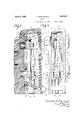
Fig. 1 is a vertical section taken through a closed switch box and fuse cartridge comprising the invention;
Fig. 2 is a front elevation of Fig. 1, certain portions being broken away;
Fig. 3 is a bottom plan view of Fig. 1;
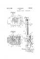
Fig. 4: is a view similar to Fig. 1, showing the door open and a fuse cartridge in partially removed position;
Fig. 5 is a cross section taken on line 5-5 of Fig. 1; and,
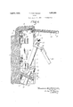
Fig. 6 is a side elevation of a fuse cartridge per se, showing the same in open position and a fuse link partially applied, and also showing an alternate position.
Similar reference characters indicate corresponding parts throughout the several views of the drawings.
Referring now more particularly to Fig. 1, there is illustrated at numeral 1 a box, composed of non-conducting material, preferably of porcelain. The box in its finished commercial form is preferably of a unitary recesses 13.
1929. Serial No. 356,359.
construction, the various members thereof being baked together and comprising aback 3, a backwardly sloping top 5, side walls 7 and a septum 9. Recesses 11 are provided in the rear for cementing on suitable supporting means. The outer surfaces of the side walls 7 are provided with elevations 8 for increasing the leakage path. The forward opening in the box has edges in which are formed longitudinal depressions or recesses 13 for receiving the extending edges 14L of a door 15,
the door being so formed as to come flush with the front of said box 1. By this means a tortuous crack, rather than a straight one is effected between the door and box, by means of which a better enclosing eflect is had. The door 15 is hinged at the top of the box by means'of a pin 17 At its lower end it is provided with an external finger piece 19 for opening and closing purposes.
Also, when the door is drawn open, as illus trated in Fig. 41, then the bent or curved portions 23 of the detents spring outwardly and drop into their respective longitudinal door The door is thus held in open position. The economy of this construction is apparent, because it may be seen that the same recesses 13 that serve as a door stop and to more completely close thebox against weather, also serve as recesses for the action of the detents 21.
Cemented into the inside of the back 3 of the box 1 are suitable line terminals 25, comprising wire sockets 27 and spring clips 29. The sockets 27 are arranged with cross passages 31, each of which is laterally tapped for set screws for wire holding purposes. The pair of set screws provided for each socket 27 may be used with either passage 31, whereby wires may be brought in from either side of the switch through either combination of openings 33, or from one side only.
The spring clips 29 are of the type adapted to receive therebetween in electrical contact the fiat sided terminal engaging elements of the fuse cartridge C. The cartridge includes the upper element 35 having screw means 37 thereon for holding a fuse wire 38 in electrical contact, This upper element is also formed with a bridge portion 39 for hooking on an insulated tool 40 for removing and applying the cartridge. A long gasexpulsive insulating tube 41 is fastened to the upper engaging element 35 and surrounds said fuse link 38 down to a hair pin turn 43 on the latter.
The insulating tube 41 passes with a snug fit through the lower terminal engaging element-35. It is not held 'to the same'with any device such as a set screw, because these have been found to damage the tube and promote leakage, so that an are (such as is formed upon blowing) connects the terminals 35 over the shortest possible distance, namely through the portion of the tube 41 between said terminals.
The terminal engaging element 35 carries downwardly extending lugs cooperating hingedly by means of a pin 62 with a lug 64, the latter lug 64 being formed with what will be designated as a short, open-sided, insulating member or cover 45. It is preferable that the member 45 be composed of fibre or the like and the lug 64 be formed integrally therewith, also of fibre. The cross sectional shape of the tube 45 is shown as a crescent in Fig. 3 and comprises a solid portion 66 having a longitudinal open slot or opening 68 which is open when the tube 45 is hinged open as illustrated in Fig. 6. WVhen the tube 45 is hinged shut, as illustrated in Figs. 1 and 4, then the open side "of the slot 68 is closed by the contiguous tube 41 against which the member 45 rests at that time.
The lower terminal engaging element 35 is provided with a recess 70 into which the longitudinal opening 68 leads when the member 45 is closed. The recess is intersected by a set screw 53 threaded thereinto, the said screw serving .as a fastening for the fuse link when it is in connected position.
A further improvement of the lower terminal 35, taken in connection with the septum 9, consists in said lower and rearward extension 51, which in effect comprises two follower lugs 55, one on each side of the tube 41. These lugs engage the upper forwardly sloping surface of the septum 9. This upper surface, composed of porcelain, similar to the remainder of the box, is preferably glazed and is therefore smooth. It is to be understood that the septum may be constructed of otliier material such as fiber, bakelite or the li e.
The septum 9 is provided with an opening 57 having an upper beveled portion 59 forwardly and a lower beveled portion 61 rearwardly, said opening being adapted to receive the lower ends of the tubes 41, 45 snugagainst the tube 41, whereby, in effect said i member 45 comprises part of a tube, one wall of which is a portion of the wall of the tube 41 (see Fig. 1). It is also to be noted that as the lower terminal is engaged, the cartridge tends to rotate therein, thereon effecting a re- 1 action at point X (Fig. 4) so as to positively close the member 45 and form a complete tubular portion about the fuse link therein.
It will be seen that the septum is not at the lowermost region of the box 1 but is raised somewhat, so that when the cartridge is in terminal engaging position then the lower end of the cartridge, for purposes of protection, is within the confines of the back 3, side I walls 7 and door 15.
The switch may be supplied with a fuse cartridge by opening the door to the Fig. 4 position and inserting the lower end of the cartridge through the opening in the septum.
The member 45 is at this time manually held against the tube 41.
The lugs 55 limit the degree of insertion. This is an easy operation because the fit is loose.
lVhen the lugs strike the septum, the operator pushes the cartridge back into the Fig. 1 position with the terminal engaging elements 35 within the confines of the terminals 29. At this time the lugs 55 ride up on the sloping septum with the cartridge pivoting at point- X (Fig. 4) so that there is always attained a proper and accurate engagement. No high degree of skill nor care needs be exercised in pushing home the cartridge. Lugs 56 above the lugs 55 engage beneath the lower set of spring clips 29 so as to prevent upward disconnecting movement of the cartridge when the reaction due to a blowing fuse is effected.
Removal is effected by applying the tool hook at bridge 39 and drawing down the cartridge. It pivots on the lugs 55 until contact is broken and then falls forward to a position slightly beyond the Fig. 4 position. After this the cartridge may be pulled out of the septum opening 57 by hand or with the tool.
The advantage of this construct-ion is that it greatly simplifies the manufacture. Also. the cartridge is positively placed in a position where the lower open ends of the tubes are 3 gaging elements adapted to outside of the box, so that when the cartridge blows gases are not engendered within the box.
The advantage of the cartridge per se is when it is withdrawn from the box, the opensided cover member45 may be hinged open and the set screw 53 withdrawn, whereupon the portion of the fuse in the recess 70 may be readily removed. The other portion in the tube 41 may be removed from the upper end thereof by removing the cap screw 37.
Furthermore, when it is desired tore-insert a new fuse link, this may readily be done by feeding it through the tube all and fastening it at the upper terminal engaging element by means of the screw 37. It may then be readily bent around and fed into the recess 70 of the lower terminal engaging element without the necessity for feeding it through a second tube, such as would be required if the member were a stationary tube annexed to the tube d1. rafter the fuse link is fastened in position as indicated by dotted lines in Fig. 6, the cover member 1:5 may be brought into its closed position over its respective length of fuse such as shown in Fi 1 or l and thereafter the fuse cartridge is ready to be applied to the septum 9 as above de scribed. It will be seen that the member 45 rests against the tube 41 and forms a second tube which is openable along its length and removable after having been opened. In view of the above, it will be seen that the several objects of the invention are achieved and other advantageous results attained.
As many changes could be made in carrying out the above constructions without departing from the scope of the invention, it is intended that all matter contained in the above description or shown in the accompanying drawings shall be inter Jreted as illustrative and not in a limiting sense.
I claim 1. A cartridge comprising terminal engaging elements spaced by nieans of a t a fuse link joining said terminal engagi g elements one portion thereof passing through said tube and another lying outside of the same and a hinged member on one of the enswing against said tube and cover said outside part of the fuse link.
and another lying outside of the same where the tube extends beyond one of the engaging elements and means hinged to said lastnamed engaging element for covering and uncovering said external portion of the link.
4:. In a fuse switch a cartridge comprising terminal engaging elements spaced by means of a tube, a fuse link joining said ten mina engaging elements one portion thereof passing through said tube and another lying outside of the same, a hinged member on one of the engaging elements adapted to swing against said tube and cover said outside part of the fuse link, supporting means for the cartridge comprising means having an opening therein, line terminals, the periphery of said opening holding the hinged member to the tube when the line terminals are engaged by the terminal engaging elements.
A cartridge comprising terminal engaging elements spaced by means of a tube, a
.se link joining said terminal engaging elements one portion thereof passing through said tube and another ying outside of the same, a hinged member on one of the engaging elements adapted to swing against said tube and cover said outside part of the fuse link and means for holding said hinged member to the tube.
6. A cartridge comprising terminal engaging elements spaced by means of a tube, a fuse link joining said terminal engaging elements one portion thereof passing through said tube and another lying outside of the same, a hinged member on one of the engaging elements adapted to swing against said tube and cover said outside part of the fuse link and means for holding said hinged member to the tube operable automatically when the cartridge is placed to make electrical contact.
7. A cartridge comprising terminal engaging elements, a fuse link joining said engaging elements and passing through a tube therebetween, a portion of said link lying externally of said. tube and a movable portion on one of the engaging elements adapted to cover and uncover the external portion of the link.
8. A cartridge comprising terminal engaging elements, a fuse link joining said engaging elements and passing through a tube therebetween, a portion of said link lying externally of said tube and a movable portion fastened to the cartridge adapted to cover and uncover the external portion of the link.
9. A cartridge comprising terminal engaging elements, fuse link joining said engaging elements and passing through a tube therebetween, a portion of said link lying externally of said tube, a movable portion fastened to the cartridge adapted to cover and uncover the external portion of the link and form a tube around said external portion of the link.
10. In a fuse cartridge an upper terminal engaging element, a lower terminal engaging element, a tube extending from the upper element through the lower element, a re cess in said lower element, a swingable portion on the lower element having an open portion accommodating a length of fuse link, said open portion leading to and communicating with said recess, a fuse link fastened to the upper element and passing through the tube, a portion of said link lying outside of the tube and comprising the length Within the swingable portion.
11. In a fuse switch, line terminals, a cartridge comprising terminal engaging elements spaced by means of a tube, a fuse link joining said terminal engaging elements one portion thereof passing through said tube and another lying outside of the same, a hinged member on one of the. engaging elements adapted to swing against said tube and cover said outside )art of the fuse link, supporting means for the cartridge comprising means having an opening therein, the periphery of said opening holding the hinged member to the tube.
12. In a fuse cartridge a tube, a juxtaposed cover, a fuse having a leg in the tube and a leg under said cover, said uxtaposed cover being movable to uncover the fuse leg there under and hingeable on the cartridge to permit ready placement of said fuse.
In testimony whereof I have signed my name to this specification this 17th day of April, 1929.
THEODORE BIR-KENMAIER.
Priority Applications (1)
| Application Number | Priority Date | Filing Date | Title |
|---|---|---|---|
| US356359A US1852283A (en) | 1929-04-19 | 1929-04-19 | Switch |
Applications Claiming Priority (1)
| Application Number | Priority Date | Filing Date | Title |
|---|---|---|---|
| US356359A US1852283A (en) | 1929-04-19 | 1929-04-19 | Switch |
Publications (1)
| Publication Number | Publication Date |
|---|---|
| US1852283A true US1852283A (en) | 1932-04-05 |
Family
ID=23401148
Family Applications (1)
| Application Number | Title | Priority Date | Filing Date |
|---|---|---|---|
| US356359A Expired - Lifetime US1852283A (en) | 1929-04-19 | 1929-04-19 | Switch |
Country Status (1)
| Country | Link |
|---|---|
| US (1) | US1852283A (en) |
-
1929
- 1929-04-19 US US356359A patent/US1852283A/en not_active Expired - Lifetime
Similar Documents
| Publication | Publication Date | Title |
|---|---|---|
| US2853819A (en) | Electric signs | |
| US1852283A (en) | Switch | |
| US1993866A (en) | Fuse | |
| US1602370A (en) | Electrical receptacle | |
| US3541381A (en) | Plug-in lighting assembly | |
| US2193201A (en) | Fuse pull-out device | |
| US1723750A (en) | Fuse-testing device | |
| US2570104A (en) | Lamp socket for elongated tubular discharge lamps | |
| US2020741A (en) | Photo flash light device | |
| US2729736A (en) | Portable electric cigarette lighter | |
| US1927372A (en) | Fuse | |
| US2027096A (en) | Utility light and test lamp | |
| US2072854A (en) | Fuse box and fuse | |
| US1394101A (en) | Electric handlamp | |
| US1422420A (en) | Renewable fuse | |
| US2292907A (en) | Electric fuse plug and fuse | |
| US1562985A (en) | Fuse | |
| US1945539A (en) | Electric fuse | |
| US1922060A (en) | Arc extinguishing device for electric switches | |
| US1935947A (en) | Multiple fuse plug | |
| GB345126A (en) | Improvements in cartridge type fuses | |
| US2059029A (en) | Switch for electric flashlights | |
| US2011449A (en) | Circuit breaker | |
| US2420837A (en) | Fuse plug | |
| US1341662A (en) | Refillable electric fuse |