US185209A - Improvement in wheel-harrows - Google Patents
Improvement in wheel-harrows Download PDFInfo
- Publication number
- US185209A US185209A US185209DA US185209A US 185209 A US185209 A US 185209A US 185209D A US185209D A US 185209DA US 185209 A US185209 A US 185209A
- Authority
- US
- United States
- Prior art keywords
- gang
- wheel
- pole
- harrows
- gangs
- Prior art date
- Legal status (The legal status is an assumption and is not a legal conclusion. Google has not performed a legal analysis and makes no representation as to the accuracy of the status listed.)
- Expired - Lifetime
Links
- 239000002689 soil Substances 0.000 description 2
- 238000010276 construction Methods 0.000 description 1
- 230000004048 modification Effects 0.000 description 1
- 238000012986 modification Methods 0.000 description 1
- 238000003756 stirring Methods 0.000 description 1
Images
Classifications
-
- A—HUMAN NECESSITIES
- A01—AGRICULTURE; FORESTRY; ANIMAL HUSBANDRY; HUNTING; TRAPPING; FISHING
- A01B—SOIL WORKING IN AGRICULTURE OR FORESTRY; PARTS, DETAILS, OR ACCESSORIES OF AGRICULTURAL MACHINES OR IMPLEMENTS, IN GENERAL
- A01B21/00—Harrows with rotary non-driven tools
- A01B21/08—Harrows with rotary non-driven tools with disc-like tools
Definitions
- My invention relates to a novel arrangement of the gangs of disks or wheels, whereby the efficiency of their action on the ground is greatly increased; and it consists in placing the gangs of reversely-dished, and, consequently, reversely-acting, disks or wheels one directly in rear of the other, in the same longitudinal plane, in such manner that the earth acted upon and moved laterally in one direction by the disks of the forward gang is moved in the opposite direction by the rear or following gang, as hereinafter described.
- A represents the rear extension ,of the pole or pole-frame, to which the gang planks or frames B B are attached.
- gang-planks are represented as being connected with the pole or frame A at or near midway of their length and one in rear of the other by vertical pins or pivots a a, which permit their angles of relation to each other, .and to the pole-frame to be adjusted, as desired.
- the wheel gang-shafts U are connected by pendent bearings in the usual manner, the disks or wheels D of the forward gang being dished and facing in the reverse direction to those of the rear gang D, as shown, for the purpose of causing them to move or throw the earth laterally in opposite directions.
- the gangs may be set obliquely to the pole-frame, and at, or nearly at, opposite angles, as shown, in such manner as that the lateral thrust'of one gang upon the pole-frame shall be compensated for, or nearly so, by the reverse thrust of the following gang.
- Any usual or preferred devices may be employed forsetting or holding the gang planks or frames at the desired angle of adjustment.
- the gangbars may be placed parallel with each other, either at rightangles or obliquely to the pole-frame, as desired, and the wheels or disks may either be connected rigidly with the shaft or theymay be supported independently, and placed at different angles, as preferred.
- Parts of the machine not particularly described may be constructed and arranged in any usual or preferred way.
Landscapes
- Life Sciences & Earth Sciences (AREA)
- Soil Working Implements (AREA)
- Engineering & Computer Science (AREA)
- Mechanical Engineering (AREA)
- Soil Sciences (AREA)
- Environmental Sciences (AREA)
Description
F. BRAMER.
' WHEEL-HARROW.
1 ,1 5,209, Patented Dec.12, 1876.
FRANK BBAMER, OF LITTLE FALLS, NEW YORK;
IMPROVEMENT IN WHEEL-HARROWS.
Specification forming part of Letters Patent No. 185,209, dated December 12, 1876; application filed June 14, 1876. e
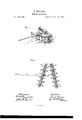
To all whom it may concern Be it known that 1, FRANK BRAMER, of Little Falls, county of Herkimer, State of New York, have invented certain new and useful Improvements in W heel-Harrows, of which the following is a full, clear, and exact description, reference being bad to the accompanying drawings, making part of this specification, in which Figure 1 is a perspective view of my improved harrow, and Fig. 2 is a bottom view of the same.
Similar letters .of reference denote corresponding parts in both figures.
My invention relates to a novel arrangement of the gangs of disks or wheels, whereby the efficiency of their action on the ground is greatly increased; and it consists in placing the gangs of reversely-dished, and, consequently, reversely-acting, disks or wheels one directly in rear of the other, in the same longitudinal plane, in such manner that the earth acted upon and moved laterally in one direction by the disks of the forward gang is moved in the opposite direction by the rear or following gang, as hereinafter described.
In the drawing, A represents the rear extension ,of the pole or pole-frame, to which the gang planks or frames B B are attached.
These gang-planks are represented as being connected with the pole or frame A at or near midway of their length and one in rear of the other by vertical pins or pivots a a, which permit their angles of relation to each other, .and to the pole-frame to be adjusted, as desired.
To these planks or frames B B the wheel gang-shafts U are connected by pendent bearings in the usual manner, the disks or wheels D of the forward gang being dished and facing in the reverse direction to those of the rear gang D, as shown, for the purpose of causing them to move or throw the earth laterally in opposite directions. Thus arranged, the gangs may be set obliquely to the pole-frame, and at, or nearly at, opposite angles, as shown, in such manner as that the lateral thrust'of one gang upon the pole-frame shall be compensated for, or nearly so, by the reverse thrust of the following gang.
Any usual or preferred devices may be employed forsetting or holding the gang planks or frames at the desired angle of adjustment.
Sometimes, instead of connecting the gangplanks to the pole or pole-frame midway of their length, as shown, it may be found desirable to hinge them thereto by their ends, and to employ a second pair having a reverse relation to each other on the other side of the tongue or tongue-frame to counterbalance the first-named pair and prevent side draft.
Other modifications in arrangement will suggest themselves to the skilled mechanic in carrying out my invention, the object of which,
as above stated, is to bring the reversely-acting gangs into the same longitudinal plane, and thereby to increase its efficiency in thoroughly stirring up and lightening the soil preparatory to its reception of the seed. Thus, the gangbars may be placed parallel with each other, either at rightangles or obliquely to the pole-frame, as desired, and the wheels or disks may either be connected rigidly with the shaft or theymay be supported independently, and placed at different angles, as preferred.
In the construction of wheel-barrows it has been the practice heretofore to place the gangs opposite each other, or thereabout, and the disks or wheels of both gangs were dished on their inner faces; consequently, both gangs threw the soil inward, forming a ridge in the center, and leaving the ground uneven and in ridges.
\IVith my arrangement this difficulty is entirely obviated, as the earth, thrown inward by the forward gang or gangs, will be thrown in a reverse direction by the rear gang, and, while it is additionally stirred thereby, is practicallyreplaced and leveled by the action of such rear gang.
Parts of the machine not particularly described may be constructed and arranged in any usual or preferred way.
Having now described my invention, what I claim as new, and desire to secure by Letters Patent, is
In a wheel harrow, the reversely acting wheelgan gs arranged one in rear of the other, and in the same, or nearly the same, longitudinal plane, substantially as and for the purpose described.
FRANK BRAMER.
Witnesses GERRET DRAKE, A. L. BURT.
Publications (1)
| Publication Number | Publication Date |
|---|---|
| US185209A true US185209A (en) | 1876-12-12 |
Family
ID=2254614
Family Applications (1)
| Application Number | Title | Priority Date | Filing Date |
|---|---|---|---|
| US185209D Expired - Lifetime US185209A (en) | Improvement in wheel-harrows |
Country Status (1)
| Country | Link |
|---|---|
| US (1) | US185209A (en) |
Cited By (1)
| Publication number | Priority date | Publication date | Assignee | Title |
|---|---|---|---|---|
| US20050154030A1 (en) * | 2003-12-12 | 2005-07-14 | Microban Products Company | Antimicrobial composition |
-
0
- US US185209D patent/US185209A/en not_active Expired - Lifetime
Cited By (1)
| Publication number | Priority date | Publication date | Assignee | Title |
|---|---|---|---|---|
| US20050154030A1 (en) * | 2003-12-12 | 2005-07-14 | Microban Products Company | Antimicrobial composition |
Similar Documents
| Publication | Publication Date | Title |
|---|---|---|
| US185209A (en) | Improvement in wheel-harrows | |
| US204793A (en) | Improvement in wheel-harrows | |
| US639829A (en) | Combined land-roller and harrow. | |
| US411650A (en) | deader | |
| US155311A (en) | Improvement in levelers, pulverizers, and corn-planters | |
| US590694A (en) | Cultivator | |
| US119361A (en) | Improvement in clod-breaking-and-pulverizing machines | |
| US162549A (en) | Improvement in plows | |
| US139814A (en) | Improvement in rotary harrows | |
| US337773A (en) | la dow | |
| US363571A (en) | Cultivator | |
| US918298A (en) | Cultivator. | |
| USRE8147E (en) | Improvement in wheel-harrows | |
| US43207A (en) | Improvement in harrows | |
| US437124A (en) | Disk harrow | |
| US344950A (en) | Disk seeder and cultivator | |
| US271142A (en) | Spade-wheel plow | |
| US210046A (en) | Improvement in farm-harrows | |
| US294112A (en) | Rotary harrow | |
| US795248A (en) | Drag-bar connection for grain-drills. | |
| US244165A (en) | Empson atkinson | |
| US102993A (en) | Improvement in cultivators | |
| US161060A (en) | Improvement in disk harrow-cultivators | |
| US273320A (en) | Combined harrow and roller | |
| US205608A (en) | Improvement in wheel-harrows |