US1852088A - Circuit closer for shuttle binders - Google Patents
Circuit closer for shuttle binders Download PDFInfo
- Publication number
- US1852088A US1852088A US541886A US54188631A US1852088A US 1852088 A US1852088 A US 1852088A US 541886 A US541886 A US 541886A US 54188631 A US54188631 A US 54188631A US 1852088 A US1852088 A US 1852088A
- Authority
- US
- United States
- Prior art keywords
- shuttle
- brushes
- binder
- box
- contact
- Prior art date
- Legal status (The legal status is an assumption and is not a legal conclusion. Google has not performed a legal analysis and makes no representation as to the accuracy of the status listed.)
- Expired - Lifetime
Links
- 239000011230 binding agent Substances 0.000 title description 32
- 230000007246 mechanism Effects 0.000 description 8
- 230000009471 action Effects 0.000 description 4
- 230000000875 corresponding effect Effects 0.000 description 3
- 230000000694 effects Effects 0.000 description 3
- 239000011810 insulating material Substances 0.000 description 3
- 230000006835 compression Effects 0.000 description 2
- 238000007906 compression Methods 0.000 description 2
- 238000010276 construction Methods 0.000 description 2
- 230000001276 controlling effect Effects 0.000 description 2
- 239000002184 metal Substances 0.000 description 2
- 229910000831 Steel Inorganic materials 0.000 description 1
- 230000008901 benefit Effects 0.000 description 1
- 230000008859 change Effects 0.000 description 1
- 230000003111 delayed effect Effects 0.000 description 1
- 230000001419 dependent effect Effects 0.000 description 1
- 239000004744 fabric Substances 0.000 description 1
- 239000010985 leather Substances 0.000 description 1
- 239000000463 material Substances 0.000 description 1
- 230000004048 modification Effects 0.000 description 1
- 238000012986 modification Methods 0.000 description 1
- 230000000630 rising effect Effects 0.000 description 1
- 239000010959 steel Substances 0.000 description 1
- 238000006467 substitution reaction Methods 0.000 description 1
- 210000002105 tongue Anatomy 0.000 description 1
- 239000002023 wood Substances 0.000 description 1
Images
Classifications
-
- D—TEXTILES; PAPER
- D03—WEAVING
- D03D—WOVEN FABRICS; METHODS OF WEAVING; LOOMS
- D03D51/00—Driving, starting, or stopping arrangements; Automatic stop motions
- D03D51/18—Automatic stop motions
- D03D51/34—Weft stop motions
Definitions
- This invention relates to electrical weft'detectors for looms and it is the general object of the invention to provide a type which will not come into action until the shuttle comes substantially to rest in the shuttle box.
- Certain types of electrical weft detectors require a shuttle having contact plates on the front wall which coact with relatively stationary contacts or brushes mounted on the lay. At the time of weft exhaustion the two plates are'el'ectrically connected by a circuit internal to the shuttle and this establishes contact between a pair of brushes which in'turn form part of a loom controlling circuit. Where the brushes or the like are in position to engage the shuttle throughout the movement of the shuttle in the box it is found that objectionable wear results, grooves being formed in the shuttle so as to expose parts of the.
- the contact plates on the shuttle may be made sufficiently long so that they will be op-.
- the brushes are moved toward the shuttle bya yielding force which permits them to be arrested by the shuttle in such a Wayas-to insuregood contact.
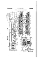
- Fig. l is a top plan view of the drop box end of a loom having my invention applied thereto, parts being in section, 1 Fig.2 is a vertical section on an enlarged scale taken on line 22 of Fig. 1, Fig. 3 is a, detail horizontal section taken on line 33 of Fig. 2, showing thebrushes in contact with the shuttle, the shuttle 'being fully boxed, and
- Fig. 4 is a view similar to Fig. 3 but with the detectors retracted due to absence of the shuttle.
- I have shown a lay having innerand outer box guides 11 and 12 which receive tongues 13 and 14, respec-- tively, of a gang of boxes designated general: ly at 15.
- Two shuttle boxes are set forth herein and the detector mechanism associated with each is similar to that of the other.
- a picker 16 to propel the active shuttle is slidable along a spindle 17 as is usual in drop box looms.
- the boxes are raised or lowered dependingupon' the call of a pattern chain so that one or the other of the shuttle boxes is'opposite the race 18.
- a metallic front plate 31 is pivoted as at 32 to block may be covered with leather as at 36 or any other suitable material to form a checking surface for the shuttle.
- Theleather surface is provided with inner and outer slots 37 and 38, respectively, which I register with cavities 39 and 40, respectively,
- the wooden block is provided with a long slot 50 in the front wall thereof in which are located two metallic push rods 51 and 52 serving as actuators for the brushes 42 and 43 respectively.
- a block of insulating ma terial 53 lies between the rods and a relative- 1y heavy compression spring 54 is seated in one end of-the slot 50 and acts on rod 51 as thel-igh-t springs 55 and acts through the lugs to hold the fingers in the normal position when the shuttle is absent.
- contacting relation with the shuttle I provide the binder block 25 with thevertica'l pivot pin on which is mounted a wooden lever 61 having a pocket 62 in which is located a compression spring 63.
- a sheet metallic facing 64 is secured to certain vertical surfaces of the lever 61 as shown in Figs. .3 and 4, said facing having a contact area'65 which is adapted for contact with the .plate 31.
- the shuttle S. which is employed in -con nection with my invention has inner and enter contact plates 70 and 71, respectively,
- these contact plates be of sufficient length to have contact with the brushes 42 and 43 whenever the latter are projected rearwardly sufliciently to contact withany part of the shuttle.
- the parts will normally be in the position shown in Fig.4, spring 54 holding the detectors retracted and spring 63 holding the lever 61 behind the plane of he shuttle engaging material-36.
- spring 63 is not essential inasmuch as its function canbe performed by its spring 54, but its presence gives added certainty to the operation of the parts. i
- the shuttle enters the box its rounded advancing nose .75 will engage the rear surface 76 of the lever 61 and .inovethe latter from the positionoshown'in Fig. 4.
- the insulating block :53 and the .rod51' is also given a right hand movement the effect of.
- an electrical weft detector for a loom having a shuttle box and a shuttle having two spaced electric contact plates, a binder ivoted to the box and havin a shuttle engaging surface, a pair of brushes having plate engaging surfaces insulated from each other and movably mounted on the binder, yielding means normally holding the plate engaging surfaces of said brushes outside of the shuttle engaging surface of the binder, with respect to the shuttle, and means mounted on the binder to be engaged by the shuttle as the latter nears the end of its flight w and effective to project the brushes against the plates by a force derived from the shuttle.
- an electrical weft detecting mechanism for a loom having a shuttle box and a shuttle provided with a pair of spaced contact plates, a binder pivoted to the box and having a body of insulating material secured thereto, a pair of brushes insulated from each other and pivoted to the body, yielding means to hold the brushes out of engaging position relatively to the plates when the shuttle is out of the box, and a device movably mounted on the binder and operatively connected to the brushes to be effective when engaged by the shuttle to move the brushes into engagement with the plates on the shuttle.
- an electrical weft detecting mechanism for a loom having a shuttle box and a shuttle provided with a pair of spaced contact plates, a binder pivoted to the outer end of the shuttle box, a pair of contact brushes pivoted to the binder and insulated from each other, an actuator element operatively related to each brush, a pressure transmitter of insulating material interposed between and insulating the elements from each other, yielding means normally holding the brushes out of engaging position relatively to the plates on the shuttle, and a device pivoted to the binder adjacent the pivot of the latter box, a pair of brushes movably mounted on the binder and insulated from each other, gielding means tending normally to hold the rushes out of plate-engaging position, additional yielding means operatively connected to each brush, a devicepivotally mounted on the binder and positioned to engage the shuttle as the latter nears the end of its flight and operative connections between said device and the additional'yielding means, movement of the device by the shuttle communicating a force to the additional
- an electrical weft detector mechanism for a loom having a shuttle box and a shuttle provided with a pair of spaced contact plates, a binder pivoted to the outer end of the shuttle box, a pair of brushes, one for each plate, said brushes pivoted to the binder and insulated from each other, a pair of actuating rods slidably mounted on the binder longitudinally'of the latter, each rod being operatively connected to one of the brushes, a force transmitting insulated connection between the rods, yielding means acting on one end of one of the rods to hold said brushes normally out of plate engaging position, and a lever pivoted to the binder adjacent the pivot of the latter and operatively connected to the other rod, said lever to be engaged by a shuttle as the latter nears the end of its flight to move said rod longitudinally of the binder and position the brushes for engagement with the'plates.
- each brush and the corresponding rod comprises a spring which is yieldable subsequent to engagement of the brush and corre sponding plate.
- an electrical weft detecting mechanism for a loom having a shuttle box and a shuttle provided with a pair of spaced contact plates, a binder pivoted to the outer end of the shuttle box, a pair of brushes, one for each plate, said brushes pivoted to the binder and insulated from each other, means dependent upon movement of the shuttle and determined by the position of the latter to project the brushes into engaging position relatively to the plates, the latter being of such length v that they will be engaged by their respective to move the brushes against any part of the shuttle except the plates.
- an electrical weft detecting mechanism fora loom having a shuttle box and a shuttle provided with a pair of spaced contact plates, a binder pivoted to the outer end of the shuttle boX, a pair of brushes, one for each plate, said brushes pivoted to the binder and insulated from each other, a device mounted on and movable with respect to the binder to be engaged by the shuttle, and operative connections between said device and the brushes effective to move the latter to ward the shuttle and engage the plates only, whereby engagement of the brushes with the body of the shuttle is prevented.
Landscapes
- Engineering & Computer Science (AREA)
- Textile Engineering (AREA)
- Looms (AREA)
Description
Patented Apr. 5, 1932 UNITED STATES rFiciE ERNEST H. PAULSON, OF WORCESTER, MASSACHUSETTS, 'ASSIGNOR TO CROMPTON &1 v
KNOWLES LOOM WORKS, 013 WORCESTER, MASSACHUSETTS, A CORPORATION F MASSACHUSETTS CIRCUIT CLOSER FOR SHUTTLE BINDERS I Application filed June a, 1931. Serial No. 541,886.
This invention relates to electrical weft'detectors for looms and it is the general object of the invention to provide a type which will not come into action until the shuttle comes substantially to rest in the shuttle box.
Certain types of electrical weft detectors require a shuttle having contact plates on the front wall which coact with relatively stationary contacts or brushes mounted on the lay. At the time of weft exhaustion the two plates are'el'ectrically connected by a circuit internal to the shuttle and this establishes contact between a pair of brushes which in'turn form part of a loom controlling circuit. Where the brushes or the like are in position to engage the shuttle throughout the movement of the shuttle in the box it is found that objectionable wear results, grooves being formed in the shuttle so as to expose parts of the.
contact plates. Another result of contact between the shuttle and the brushes is that the former are roughened to an extent which makes their use undesirable in the type of looms where electrical weft detectors are ordinarily used to their best advantage, that is, in silk and fine fabrics. It is accordingly a further object of my present invention to provide a pair of brush contactsmounted on the lay and normally retracted out of shuttle engaging position, together with means operative by the shuttle as the latter nears the end of its flight to project said brushes into shuttle engaging position.
' The contact plates on the shuttle may be made sufficiently long so that they will be op-.
posite the brushes when the latter move into the plane of the front wall of the shuttle. In this way a metal to metal contact is secured and the brushes are kept from having engagement with the shuttle.
It is a further object of my invention to provide a binder to check the flight of the shuttle and including in its make-up a-pair of brushes and an actuating lever which operates through force transmitting elements movable with respect to the binder to project the brushes into detecting position. The brushes are moved toward the shuttle bya yielding force which permits them to be arrested by the shuttle in such a Wayas-to insuregood contact. a
With these andother objects in View which will appear as thedescription proceeds, my invention resides in the combination and arrangement of parts-hereinafter described and set forth in the claims. In the accompanying drawings, wherein a convenient embodiment of my invention is set forth,
Fig. l is a top plan view of the drop box end of a loom having my invention applied thereto, parts being in section, 1 Fig.2 is a vertical section on an enlarged scale taken on line 22 of Fig. 1, Fig. 3 is a, detail horizontal section taken on line 33 of Fig. 2, showing thebrushes in contact with the shuttle, the shuttle 'being fully boxed, and
Fig. 4 is a view similar to Fig. 3 but with the detectors retracted due to absence of the shuttle. Referring to Fig. 1, I have shown a lay having innerand outer box guides 11 and 12 which receive tongues 13 and 14, respec-- tively, of a gang of boxes designated general: ly at 15. Two shuttle boxes are set forth herein and the detector mechanism associated with each is similar to that of the other. A picker 16 to propel the active shuttle is slidable along a spindle 17 as is usual in drop box looms. By mechanism not shown the boxes are raised or lowered dependingupon' the call of a pattern chain so that one or the other of the shuttle boxes is'opposite the race 18. Thematter thus far described is of c0mmon construction, the gang ofboxes having a wall 19 which limits rearward movement of the shuttle. In carrying my invention into effect I provide each box with a binder and inasmuch as the binders and the parts carried by them are alike, I will describe but one of them. A metallic front plate 31 is pivoted as at 32 to block may be covered with leather as at 36 or any other suitable material to form a checking surface for the shuttle.
Theleather surface is provided with inner and outer slots 37 and 38, respectively, which I register with cavities 39 and 40, respectively,
cut in the wooden block 35. There is extending vertically through each of the cavities a pivot pin 41 which supports detector brushes or fingers 42 and 43 located in the cavities 39 and 40, respectively.
The wooden block is provided with a long slot 50 in the front wall thereof in which are located two metallic push rods 51 and 52 serving as actuators for the brushes 42 and 43 respectively. A block of insulating ma terial 53 lies between the rods and a relative- 1y heavy compression spring 54 is seated in one end of-the slot 50 and acts on rod 51 as thel-igh-t springs 55 and acts through the lugs to hold the fingers in the normal position when the shuttle is absent.
-'In order that the brushes or fingers may be projected into: contacting relation with the shuttle I provide the binder block 25 with thevertica'l pivot pin on which is mounted a wooden lever 61 having a pocket 62 in which is located a compression spring 63. A sheet metallic facing 64 is secured to certain vertical surfaces of the lever 61 as shown in Figs. .3 and 4, said facing having a contact area'65 which is adapted for contact with the .plate 31.
In order that the brush 42 and its rod 51 insulated from the plate 31 I interpose a sheet of insulating material 66 between said plate 31 and the rod 51. Asia matter of convenience this strip may extend between the rod, 52 and the steel plate of t the binder, but this latter relation is not essential inasmuch as the brush or. finger 43, together with its actuating red, are ;con-
nectedto the grounded side ofjthe loom con troll-ingcircui-t. By the use of the construction set forth herein, however, assurance is given that both of the fingers or brushes will be out: of contact. with the ground except at the proper time.
"The shuttle S. which is employed in -con nection with my invention has inner and enter contact plates 70 and 71, respectively,
closed when weft issubstantia'lly absent in the shuttle. It is desirable that these contact plates be of sufficient length to have contact with the brushes 42 and 43 whenever the latter are projected rearwardly sufliciently to contact withany part of the shuttle.
In operation, the parts will normally be in the position shown in Fig.4, spring 54 holding the detectors retracted and spring 63 holding the lever 61 behind the plane of he shuttle engaging material-36. I have found in practice that the spring 63 is not essential inasmuch as its function canbe performed by its spring 54, but its presence gives added certainty to the operation of the parts. i As the shuttle enters the box its rounded advancing nose .75 will engage the rear surface 76 of the lever 61 and .inovethe latter from the positionoshown'in Fig. 4.
to t-nat shown in Fig. 3.. During-this movemen-t rod 52 is moved .to the right in the slot '50 and lug isalso moved to the right. The
right end of the spring 55 is also movedtoward the inner .endof the binder,,.so that brush or finger 43 turns ,angularly on its to the right it communicates force through.
the insulating block :53 and the .rod51' is also given a right hand movement the effect of.
which is to project the contacting'surface of brush- 42 rearwardly to the position shown. in 3. If the switch 74 be opendueto the presence of su-fiicient weft nocontact; will he made between the brushes, butif said switchshould be cl osed,as indicatedin dotted lines in Fig. 3, current will flow "from ba ttery 80 over wire 81, up through the pin 41 corresponding to finger 42, through the latter plate 70, wire 72, switch74, .wire 73., plate 71, finger 43.,spring 55, rod 52, metallic fa-c ing 64, to the plate 31., which is grounded. Current rising from the ground will' p'ass through the wire. 80 to m controll-ing'electromagnetic device M .and return to the battery. Current flowing in'this circuit will energize the device M to effect a change in the operation of the loom, saidchange being either replenishment of the weft .by substitution of a new shuttle or "bobbin, or loom stoppage,.according to which of these results is desired. It will be noted that the. brushes 42 and 43 are moved into contacting position by springs 55 and may therefore yield Q should the rods 51 and 52 move more than is necessary.
It is desirable to have "the binder carried lever 61 so related to the shuttle that it will delay rearward movemento-f the fingers 42 and 43 until the contact plates-70 and 71 lie.
bpposite their respective fingers. In this way contact between the fingers and the wooden part ofthe shuttle is prevented;
'VVhcn' the shuttle is picked out of the box the lever 61 will be returned to the position shown in Fig; 4 by the action of spring 54 and, also of spring 63, if the latter be prescut. This action takes place while the contact plates of the shuttle are sliding along the lingers or brushes so that the latter do not contact withthe wood of the shuttle when the latter is being picked out of the box.
From the foregoing, it will be seen that I have provided means for establishing electrical connections with a shuttle operative by the latter as the same nears the end of its flight, the action being preferably delayed until the fingers or brushes carried by the binder will engage metallic plates on the shuttle without striking the wooden body of the latter.
Having thus described my invention it will be seen that changes and modifications may be made therein by those skilled in the art without departing from the spirit and scope of the invention and I do not wish to be limited to the details herein disclosed, but what I claim is:
1. In an electrical weft detector for a loom having a shuttle box and a shuttle having two spaced electric contact plates, a binder ivoted to the box and havin a shuttle engaging surface, a pair of brushes having plate engaging surfaces insulated from each other and movably mounted on the binder, yielding means normally holding the plate engaging surfaces of said brushes outside of the shuttle engaging surface of the binder, with respect to the shuttle, and means mounted on the binder to be engaged by the shuttle as the latter nears the end of its flight w and effective to project the brushes against the plates by a force derived from the shuttle.
2. In an electrical weft detecting mechanism for a loom having a shuttle box and a shuttle provided with a pair of spaced contact plates, a binder pivoted to the box and having a body of insulating material secured thereto, a pair of brushes insulated from each other and pivoted to the body, yielding means to hold the brushes out of engaging position relatively to the plates when the shuttle is out of the box, and a device movably mounted on the binder and operatively connected to the brushes to be effective when engaged by the shuttle to move the brushes into engagement with the plates on the shuttle.
3. In an electrical weft detecting mechanism for a loom having a shuttle box and a shuttle provided with a pair of spaced contact plates, a binder pivoted to the outer end of the shuttle box, a pair of contact brushes pivoted to the binder and insulated from each other, an actuator element operatively related to each brush, a pressure transmitter of insulating material interposed between and insulating the elements from each other, yielding means normally holding the brushes out of engaging position relatively to the plates on the shuttle, and a device pivoted to the binder adjacent the pivot of the latter box, a pair of brushes movably mounted on the binder and insulated from each other, gielding means tending normally to hold the rushes out of plate-engaging position, additional yielding means operatively connected to each brush, a devicepivotally mounted on the binder and positioned to engage the shuttle as the latter nears the end of its flight and operative connections between said device and the additional'yielding means, movement of the device by the shuttle communicating a force to the additional yielding means and the latter moving the brushes to plate engaging position.
5. In an electrical weft detector mechanism for a loom having a shuttle box and a shuttle provided with a pair of spaced contact plates, a binder pivoted to the outer end of the shuttle box, a pair of brushes, one for each plate, said brushes pivoted to the binder and insulated from each other, a pair of actuating rods slidably mounted on the binder longitudinally'of the latter, each rod being operatively connected to one of the brushes, a force transmitting insulated connection between the rods, yielding means acting on one end of one of the rods to hold said brushes normally out of plate engaging position, and a lever pivoted to the binder adjacent the pivot of the latter and operatively connected to the other rod, said lever to be engaged by a shuttle as the latter nears the end of its flight to move said rod longitudinally of the binder and position the brushes for engagement with the'plates.
6. The type of 'mechanism set forth in claim 5 wherein the operative connection between. each brush and the corresponding rod comprises a spring which is yieldable subsequent to engagement of the brush and corre sponding plate.
7. In an electrical weft detecting mechanism for a loom having a shuttle box and a shuttle provided with a pair of spaced contact plates, a binder pivoted to the outer end of the shuttle box, a pair of brushes, one for each plate, said brushes pivoted to the binder and insulated from each other, means dependent upon movement of the shuttle and determined by the position of the latter to project the brushes into engaging position relatively to the plates, the latter being of such length v that they will be engaged by their respective to move the brushes against any part of the shuttle except the plates.
8. In an electrical weft detecting mechanism fora loom having a shuttle box and a shuttle provided with a pair of spaced contact plates, a binder pivoted to the outer end of the shuttle boX, a pair of brushes, one for each plate, said brushes pivoted to the binder and insulated from each other, a device mounted on and movable with respect to the binder to be engaged by the shuttle, and operative connections between said device and the brushes effective to move the latter to ward the shuttle and engage the plates only, whereby engagement of the brushes with the body of the shuttle is prevented.
In testimony whereof I have hereunto affixed my signature.
ERNEST H. PAULS'ON.
Priority Applications (1)
| Application Number | Priority Date | Filing Date | Title |
|---|---|---|---|
| US541886A US1852088A (en) | 1931-06-03 | 1931-06-03 | Circuit closer for shuttle binders |
Applications Claiming Priority (1)
| Application Number | Priority Date | Filing Date | Title |
|---|---|---|---|
| US541886A US1852088A (en) | 1931-06-03 | 1931-06-03 | Circuit closer for shuttle binders |
Publications (1)
| Publication Number | Publication Date |
|---|---|
| US1852088A true US1852088A (en) | 1932-04-05 |
Family
ID=24161502
Family Applications (1)
| Application Number | Title | Priority Date | Filing Date |
|---|---|---|---|
| US541886A Expired - Lifetime US1852088A (en) | 1931-06-03 | 1931-06-03 | Circuit closer for shuttle binders |
Country Status (1)
| Country | Link |
|---|---|
| US (1) | US1852088A (en) |
-
1931
- 1931-06-03 US US541886A patent/US1852088A/en not_active Expired - Lifetime
Similar Documents
| Publication | Publication Date | Title |
|---|---|---|
| US1852088A (en) | Circuit closer for shuttle binders | |
| US1832530A (en) | Weft detector for looms | |
| US1362119A (en) | Feeler mechanism for looms | |
| US2206843A (en) | Box plate | |
| US1462554A (en) | Weft-detector mechanism | |
| US1873108A (en) | Weft detecting mechanism for drop box looms | |
| US1807722A (en) | S-igjstors to cromptoet | |
| US1609542A (en) | Bobbin release for loom weft-replenishing mechanism | |
| US2248847A (en) | Shuttle ejector | |
| US1587180A (en) | Automatic filling replenishing loom | |
| US1649776A (en) | Feeler mechanism for looms | |
| US2042119A (en) | Loom shuttle check | |
| US1862762A (en) | Electric feeler mechanism for looms | |
| US2599108A (en) | Shuttle box | |
| US2112806A (en) | Shuttle check | |
| US1610701A (en) | Shuttle-box tension-controlling mechanism for looms | |
| US2291951A (en) | Electric feeler | |
| US1387327A (en) | Feeler mechanism for looms | |
| US1899620A (en) | Electrical weft detector for looms | |
| US1873182A (en) | Weft detecting mechanism for double shuttle looms | |
| US1926167A (en) | Electric feeler mechanism for looms | |
| US1559172A (en) | Shuttle and picker check for looms | |
| US1647870A (en) | Smash preventer | |
| US1369490A (en) | Melvin l | |
| US1398699A (en) | Shuttle-positioner |