US1852086A - Compressed air propulsion means - Google Patents
Compressed air propulsion means Download PDFInfo
- Publication number
- US1852086A US1852086A US465370A US46537030A US1852086A US 1852086 A US1852086 A US 1852086A US 465370 A US465370 A US 465370A US 46537030 A US46537030 A US 46537030A US 1852086 A US1852086 A US 1852086A
- Authority
- US
- United States
- Prior art keywords
- wing
- magazines
- propulsion means
- compressed air
- exhaust nozzle
- Prior art date
- Legal status (The legal status is an assumption and is not a legal conclusion. Google has not performed a legal analysis and makes no representation as to the accuracy of the status listed.)
- Expired - Lifetime
Links
Images
Classifications
-
- B—PERFORMING OPERATIONS; TRANSPORTING
- B64—AIRCRAFT; AVIATION; COSMONAUTICS
- B64D—EQUIPMENT FOR FITTING IN OR TO AIRCRAFT; FLIGHT SUITS; PARACHUTES; ARRANGEMENTS OR MOUNTING OF POWER PLANTS OR PROPULSION TRANSMISSIONS IN AIRCRAFT
- B64D27/00—Arrangement or mounting of power plant in aircraft; Aircraft characterised thereby
- B64D27/02—Aircraft characterised by the type or position of power plant
- B64D27/16—Aircraft characterised by the type or position of power plant of jet type
- B64D27/18—Aircraft characterised by the type or position of power plant of jet type within or attached to wing
Definitions
- G. S. MITTELSTAEDT COMPRESSED AIR PROPULSION MEANS Filed July 2, 1930 ⁇ inventor fluowwgw i atented Apr. 5, 1932 are GEOBG S. MITTELSTAEM, E BROOKLYN, NEW YORK COMPRESSED AIR PROPULSION MEANS Application filed July 2, 1930. Serial No.- 485,870.
- the main object of this invention is to propel vehicles such as an aeroplane by building up or augmenting an opposing air stream which latter is momentarily captured in coma partments, the captured air stream being compressed in the compartments and then exhausted at a point rearward of its intake, thereby utilizing this captured air stream as a lifting or directional propulsion force.
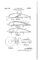
- Figure i 1 is a sectional elevational view of a sustaining wing showing the combination used for directional flight.
- Figure 2 is a view similar to Figure 1 showing the use of cylinders for directional 2 propulsion.
- Figure 3 is a view similar to Figure 1 in which lifting cylinders are used.
- Figure 4 is a front elevational view of a dirigible airship showing the propulsion 25 means applied thereto.
- Figure 5 is a sectional elevational view through an aeroplane wing showing the arrangement of cylinders in series.
- the numeral indicates the entering edge of an aeroplane sustaining wing.
- This sustaining wing is preferably of hollow construction and is perfectly streamlined to oii'er the minimum of resistance while in flight.
- the aeroplane wing has a convex roof 11, a tipped receding edge 12 and a floor 13 intermediate the length of the wing, a dividing wall 14 is constructed which divides the chamber in the wing into two compartments.
- the forward compartment 15 behind the entering edge 10 of the sustaining wing receives a stream of air thru a circular or elongated port 16.
- the dividing wall 14 has one end of an exhaust nozzle 17 connected thereto. This exhaust nozzle communicates with the compartment 15 and with atmosphere its rear end.
- a second exhaust nozzle 18 is provided in the floor 13 of the sustaining wing and is preferably located at the intersection of the dividing wall and the floor.
- FIG. 1 Another modification is shown in Fi ure 3 of the drawings.
- su stantially conical magazines 22 are mounted within the confines of the wing. These magazines in this modification have their bases suspended from the roof 11 of the aeroplane wing, and the apex is provided with an exhaust nozzle 23 which passes through the floor 13 of the wing structure.
- An air entrance conduit 24 has its open end proceeding from the entering edge 10 of the sustaining wing and communicates with the magazines 23 through the conical side there- I of. I propose to apply this principle todirigibles as well as to the other types of vehicles in which great speed is attained.
- the tips 25 of the dirigible are provided with open ends of entranoeconduits 26. These conduits pass through the hollow balancing wing 27 in which a hollow chamber 28 is formed. At the receding ends of the balancing wing slits 29 are provided which permit the communication of the compartments 28 with atmosphere.
- the propulsion means described herein may be used as an auxiliary or the like and utilizes the opposing air stream.
- nozzle 18 for lifting is provided and both nozzles are alternately opened or closed depending'upon whether lift or direct propulsion is intended.
- Figures 2 and 3 of the drawings the same princi le is involved as in Figure 1, but in these gures magazines are used into which the air from the air stream is delivered through conduits.
- Figure 2 shows an exhaust nozzle as applied for a directional flight .
- Figure 3 shows the nozzle applied for lifting the sustaining wing.
- Dirigibles may have the same principle applied thereto in the manner shown in Figure 4, in which a delivery conduit 26 communicates with a hollow compartment 28' in a balancing wing mounted on the sides of the dirigible and the air delivered into the chamber 28 is exhausted through the slit 29 in the wing as it is being used for lifting or for propulsion means.
- hese magazines may be arranged-in series one beside the other as illustrated in Figure 5. These magazines are preferably welded or secured to each other in some desirable manner so that the magazines will form a frbgame or body for wing fabric to be draped a out.
- a longitudinal stream lined body hollow magazines in said body, conduits communicating with the atmosphere at the entering edge of said body and with said magazines, a nozzle extending angularly from said cylinders opening into the atmosphere, said conduit being greater in diameter than said exhaust nozzle, said magazines being conical, the apex of said magazines having said exhaust nozzle communicating therewith.
- a longitudinal stream lined body hollow frustoconical magazines in said body, said magazines being larger at the forward end and tapering rearward to an apex, conduits communicating with the atmosphere at the entering edge of said body and with said magazines, a nozzle extending angularly from said magazines opening into the atmosphere, said conduit being greater in diameter than said exhaust nozzle, the apex of said conical magazines having said exhaust nozzle communicating therewith.
Description
April 5, 1932.
G. S. MITTELSTAEDT COMPRESSED AIR PROPULSION MEANS Filed July 2, 1930 {inventor fluowwgw i atented Apr. 5, 1932 are GEOBG S. MITTELSTAEM, E BROOKLYN, NEW YORK COMPRESSED AIR PROPULSION MEANS Application filed July 2, 1930. Serial No.- 485,870.
The main object of this invention is to propel vehicles such as an aeroplane by building up or augmenting an opposing air stream which latter is momentarily captured in coma partments, the captured air stream being compressed in the compartments and then exhausted at a point rearward of its intake, thereby utilizing this captured air stream as a lifting or directional propulsion force.
The above and other objects will become apparent in the description below in which characters of reference refer to like-named parts in the drawings.
Referring briefly to the drawings, Figure i 1 is a sectional elevational view of a sustaining wing showing the combination used for directional flight.
Figure 2 is a view similar to Figure 1 showing the use of cylinders for directional 2 propulsion.
Figure 3 is a view similar to Figure 1 in which lifting cylinders are used.
Figure 4 is a front elevational view of a dirigible airship showing the propulsion 25 means applied thereto.
Figure 5 is a sectional elevational view through an aeroplane wing showing the arrangement of cylinders in series.
Referring in detail to the drawings, the numeral indicates the entering edge of an aeroplane sustaining wing. This sustaining wing is preferably of hollow construction and is perfectly streamlined to oii'er the minimum of resistance while in flight. The aeroplane wing has a convex roof 11, a tipped receding edge 12 and a floor 13 intermediate the length of the wing, a dividing wall 14 is constructed which divides the chamber in the wing into two compartments. The forward compartment 15 behind the entering edge 10 of the sustaining wing receives a stream of air thru a circular or elongated port 16. The dividing wall 14 has one end of an exhaust nozzle 17 connected thereto. This exhaust nozzle communicates with the compartment 15 and with atmosphere its rear end. A second exhaust nozzle 18 is provided in the floor 13 of the sustaining wing and is preferably located at the intersection of the dividing wall and the floor.
wing. These magazines are arranged in series, side by side and are joined to each other so that they may form the body structure of the wing over which the fabric providing the outer form is dressed. At the apex or rear of the magazines 19 an exhaust nozzle 20 is provided. This exhaust nozzle communicates with the magazines 19 and its opposite end opens into atmosphere beneath the floor 13 of the wing. The lower portion of the entering edge 10 of the wing in the modified type of device has the opened end of a conduit 21 mounted therein. This conduit communicates with the magazine 19 intermediate the length of the magazine.
Another modification is shown in Fi ure 3 of the drawings. In this figure su stantially conical magazines 22 are mounted within the confines of the wing. These magazines in this modification have their bases suspended from the roof 11 of the aeroplane wing, and the apex is provided with an exhaust nozzle 23 which passes through the floor 13 of the wing structure. An air entrance conduit 24 has its open end proceeding from the entering edge 10 of the sustaining wing and communicates with the magazines 23 through the conical side there- I of. I propose to apply this principle todirigibles as well as to the other types of vehicles in which great speed is attained. The tips 25 of the dirigible are provided with open ends of entranoeconduits 26. These conduits pass through the hollow balancing wing 27 in which a hollow chamber 28 is formed. At the receding ends of the balancing wing slits 29 are provided which permit the communication of the compartments 28 with atmosphere.
The propulsion means described herein may be used as an auxiliary or the like and utilizes the opposing air stream.
1 divides the confines dithe hollow wing into a forward and rear compartment, the former of which receives the air stream through the opening 16. This air captured in the comartment is somewhat compressed therein and is then exhausted through the exhaust 17, when directional propulsionis attained. A
' nozzle 18 for lifting is provided and both nozzles are alternately opened or closed depending'upon whether lift or direct propulsion is intended.
In Figures 2 and 3 of the drawings, the same princi le is involved as in Figure 1, but in these gures magazines are used into which the air from the air stream is delivered through conduits. Figure 2 shows an exhaust nozzle as applied for a directional flight .while Figure 3 shows the nozzle applied for lifting the sustaining wing. Dirigibles may have the same principle applied thereto in the manner shown in Figure 4, in which a delivery conduit 26 communicates with a hollow compartment 28' in a balancing wing mounted on the sides of the dirigible and the air delivered into the chamber 28 is exhausted through the slit 29 in the wing as it is being used for lifting or for propulsion means. hese magazines may be arranged-in series one beside the other as illustrated in Figure 5. These magazines are preferably welded or secured to each other in some desirable manner so that the magazines will form a frbgame or body for wing fabric to be draped a out.
It is to be noted that certain changes in 7 form and construction may be made Without departing from the spirit or scope of the invention.
I claim: 7 I
1. In a device of the class described, a longitudinal stream lined body, hollow magazines in said body, conduits communicating with the atmosphere at the entering edge of said body and with said magazines, a nozzle extending angularly from said cylinders opening into the atmosphere, said conduit being greater in diameter than said exhaust nozzle, said magazines being conical, the apex of said magazines having said exhaust nozzle communicating therewith.
2. In a device of the class described, a longitudinal stream lined body, hollow frustoconical magazines in said body, said magazines being larger at the forward end and tapering rearward to an apex, conduits communicating with the atmosphere at the entering edge of said body and with said magazines, a nozzle extending angularly from said magazines opening into the atmosphere, said conduit being greater in diameter than said exhaust nozzle, the apex of said conical magazines having said exhaust nozzle communicating therewith.
In testimon whereof I aflix my signature.
'GE RG S. MITTELSTAEDT.
Priority Applications (1)
| Application Number | Priority Date | Filing Date | Title |
|---|---|---|---|
| US465370A US1852086A (en) | 1930-07-02 | 1930-07-02 | Compressed air propulsion means |
Applications Claiming Priority (1)
| Application Number | Priority Date | Filing Date | Title |
|---|---|---|---|
| US465370A US1852086A (en) | 1930-07-02 | 1930-07-02 | Compressed air propulsion means |
Publications (1)
| Publication Number | Publication Date |
|---|---|
| US1852086A true US1852086A (en) | 1932-04-05 |
Family
ID=23847539
Family Applications (1)
| Application Number | Title | Priority Date | Filing Date |
|---|---|---|---|
| US465370A Expired - Lifetime US1852086A (en) | 1930-07-02 | 1930-07-02 | Compressed air propulsion means |
Country Status (1)
| Country | Link |
|---|---|
| US (1) | US1852086A (en) |
Cited By (1)
| Publication number | Priority date | Publication date | Assignee | Title |
|---|---|---|---|---|
| US2463864A (en) * | 1944-05-05 | 1949-03-08 | Inventors Inc | Airfoil |
-
1930
- 1930-07-02 US US465370A patent/US1852086A/en not_active Expired - Lifetime
Cited By (1)
| Publication number | Priority date | Publication date | Assignee | Title |
|---|---|---|---|---|
| US2463864A (en) * | 1944-05-05 | 1949-03-08 | Inventors Inc | Airfoil |
Similar Documents
| Publication | Publication Date | Title |
|---|---|---|
| US1871396A (en) | Means of reducing the fluid resistance of automobile bodies | |
| ES2088999T3 (en) | SUPERSONIC MISSILES PILOTED IN PAIR THROUGH ESPOILERS. | |
| US1852086A (en) | Compressed air propulsion means | |
| US2961188A (en) | Lift-propulsion device for aircraft | |
| US1697770A (en) | Aircraft | |
| GB518663A (en) | Improvements in or relating to aircraft, hydroplanes and the like | |
| GB438991A (en) | Improvements in or relating to means for reducing the resistance to motion of material bodies | |
| US2687262A (en) | Jet propelled channeled aircraft | |
| US2383559A (en) | Airplane launching device and carrier | |
| US2071221A (en) | Airplane | |
| US3704842A (en) | Contoured stack of jet engine with channel wing aircraft | |
| US2399839A (en) | Flying machine | |
| US2360116A (en) | Airplane control mechanism | |
| US1523715A (en) | Aeroplane passenger-transfer apparatus | |
| US1782753A (en) | Aero auxiliary cylinder | |
| US1703612A (en) | Aircraft heater | |
| US1973835A (en) | Take-off device for aeroplanes | |
| US1879857A (en) | Aircraft | |
| US1864438A (en) | Aeroplane | |
| US2027259A (en) | Air distributing means for passenger cars | |
| US3618877A (en) | Flexible tail aircraft | |
| DE602793C (en) | plane | |
| US1853361A (en) | Propulsion and steering means for aircraft | |
| US1351069A (en) | Aeronautical apparatus | |
| US1945289A (en) | Aeroplane |