US1853361A - Propulsion and steering means for aircraft - Google Patents
Propulsion and steering means for aircraft Download PDFInfo
- Publication number
- US1853361A US1853361A US427852A US42785230A US1853361A US 1853361 A US1853361 A US 1853361A US 427852 A US427852 A US 427852A US 42785230 A US42785230 A US 42785230A US 1853361 A US1853361 A US 1853361A
- Authority
- US
- United States
- Prior art keywords
- envelope
- air
- advance
- nose portion
- passage
- Prior art date
- Legal status (The legal status is an assumption and is not a legal conclusion. Google has not performed a legal analysis and makes no representation as to the accuracy of the status listed.)
- Expired - Lifetime
Links
- 230000033001 locomotion Effects 0.000 description 15
- 230000003247 decreasing effect Effects 0.000 description 4
- 230000000694 effects Effects 0.000 description 3
- 230000002596 correlated effect Effects 0.000 description 2
- 238000009877 rendering Methods 0.000 description 2
- UFHFLCQGNIYNRP-UHFFFAOYSA-N Hydrogen Chemical compound [H][H] UFHFLCQGNIYNRP-UHFFFAOYSA-N 0.000 description 1
- 208000025814 Inflammatory myopathy with abundant macrophages Diseases 0.000 description 1
- 239000007789 gas Substances 0.000 description 1
- 239000001307 helium Substances 0.000 description 1
- 229910052734 helium Inorganic materials 0.000 description 1
- SWQJXJOGLNCZEY-UHFFFAOYSA-N helium atom Chemical compound [He] SWQJXJOGLNCZEY-UHFFFAOYSA-N 0.000 description 1
- 239000001257 hydrogen Substances 0.000 description 1
- 229910052739 hydrogen Inorganic materials 0.000 description 1
- 239000000463 material Substances 0.000 description 1
- 239000002184 metal Substances 0.000 description 1
- 230000004048 modification Effects 0.000 description 1
- 238000012986 modification Methods 0.000 description 1
- 230000000087 stabilizing effect Effects 0.000 description 1
Images
Classifications
-
- B—PERFORMING OPERATIONS; TRANSPORTING
- B64—AIRCRAFT; AVIATION; COSMONAUTICS
- B64B—LIGHTER-THAN AIR AIRCRAFT
- B64B1/00—Lighter-than-air aircraft
Definitions
- My invention relates to and has for a purpose the provision of means by which differential air pressures can be created in the atmosphere surrounding the body of an air craft, such as the envelope of a'dirigible for example in a manner to cause propulsion of the aircraft through the air.
- it is a purpose of'my invention to provide means for withdrawing air from an area in advance of the nose portion of an aircraft body such as the envelope of a dirigible, and thus decreasin the pressure of the air in advance of the ody, so that as a'result of relatively increased air pressure rearwardly of the nose portion of the body, acting upon the latter, the aircraft will be propelled forwardly.
- steering means is sion and steering means for aircraft embodgingmy invention and willthen point out t novel features'thereof in claims.
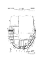
- Figure 1 is a view showing in side eleva-r tion, one form of propulsion and steering means embodying my invention, applied to the envelope of a dirigible.
- Figure '2 is an enlarged transverse sectional view taken on the line 22 of Figure 1 and looking in the direction of'the arrows..
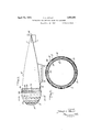
- Figure 3 is an enlarged fragmentary view partly in side elevation. and partly in longitudinal section, showing the nose portion of the envelope of the dirigible illustrated in Figure 1.
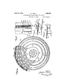
- Figure 4 is a view in front end'elevation partly broken away, of the envelope shown in Figure 3.
- Figure 5 is.a fragmentary plan view ofa further purpose of my invention to the, means by which steering movements of the dirigible are effected.
- Figure 6 is a fragmentary sectional view taken on the line 66 of Figure 5 and look ing in the direction of the arrows; and
- v igure 7 is a fragmentary detail sectional view illustratin one of a number of .control members em odied in my invention.
- My invention in its presentembodiment provides a means for'witlidrawin atmospheric air from an area in advance 0 the nose portion 13 of the envelope, and in the present instance this means comprises a rotary suction fan 14 dis osed immediately in advance of the nose portion and axially of the envelom as shown in Fi ures 3-and 4.
- the fan is irectly connecte to and positively driven by a suitable power plant 15' rigidly supported within the envelope by any suitable mount ing 16.
- I provide a'hood H preferably formed of metal and shaped to enclose the nose portion 13 of the envelope.
- the hood is supported by'struts 17 in spaced relation to the nosev portion so as to co-operate with the latter in defining an air passage 18
- the hood is loo be forced at a high velocity through the latter rearwardly of the envelope so as to discharge from an outlet 20 formed at the rear end of the hood between the latter and envelope and extending circumferentially around the latterr a
- the hood is provided with series of openings 21 in the form of circumferentially extending slots, and the material of which the hood is formed is inturiied at the openings 21 as shown at 22 in Figure 3 to'provide deflecting surfaces in the passage 18 which function to deflect air traversing the passage, away from the openings 21 and thus in'duce suction at the latter, which is operative to withdraw air from an area in advance of the hood surrounding the inlet 1-9, through the openings into the passage 18.
- v 1
- The'exterior surface of the nose portion 13 is constructed to provide a series of undulations 23 one'in advance of the other longitudinally of the envelope and extending circumferentially of the latter as clearly shown in Figures 3 and 4.
- the outlet 20 of the air passage 18 is controlled by a series of independently operable shutters 25, each of whichis hingedly mounted at 26 I on the rear edge of the hood H so as to be movable to occupy either the open position shown in full lines in Figure 6 to permit the free and unrestricted discharge of air from the passage 18, or the broken line position shown in this figure, so as toclose therespeetive portion ofthe outlet circumferentially and thus obstruct the discharge of air from the respective portion of the passage.
- each shutter is definitely limited by a stop member 27 secured to the envelope, and each shutter is rendered capable of manual actuation to its open and closed position, by the provision of an arm 28 secured to the shutter, and to which is connected, cables 29 and 30 leading in op- .posed directions from the arm and entering "flexible conduits 31 ailixed to the envelope to extend circumferentially thereof to any suitableform of control member 32 ( Figure 7-) in the pilots compartment of the cabin 10.
- Air from the area in advance ofthe nose portion surrounding the inlet 19 will also be drawn into the passage 18 through the openings 21 in the hood H, under the action of the air traversing the passage from the inlet 19 so as to decrease the pressure of the air in advance of the nose portion around the inlet, and thus aid in the forward propulsion of the aircraft as a result of the prepondcrance of air pressure acting upon the envelope rearwardly of the nose portion.
- the air traversing the passage 18 will also act upon the exterior surface of the nose portion, to produce a partial vacuum in the annular cavities 24 and thus further decrease the pressure of air in advance of the nose portion so as to aid in the forward propulsion of the aircraft.
- I- claim'as my invention I v a 1.
- means defining an air passage in surrounding relation to the nose portion of the envelope, having'a forwardly opening inlet in advance of the nose portion and an outlet circumferentially of the env lope means for drawing air in advance of t e envelope through the inlet and into said passageso as to decrease the pressure of air in advance of the envelope sufficiently for the air pressure rearwardly of the nose portion to act upon the envelope and propel the dirigible forwardly, and means responsive to the movement of air through said passage to draw additional air in advance of the encoacting with the latter to define an outlet extending circumferentially of the envelope, and means for drawing air in advance of the envelope through the inlet and into said passage so as to decrease the pressure of air in advance of the envelope sufficiently for the air pressure rearwardly of the nose portion to act u on the envelope and propel the latter forwarc 1y, the'hood having openings through which air in advance of the envelope is drawn into said passage in response to movement
- a dirigible in combination with the envelope of a dirigible means defining an air passage 1n surrounding relation to the nose portion of the envelope, having a forwardly opening inlet in advance of the nose portion and an outlet circnmferentially of the envelope, means for drawing air in advance of the envelope through the inlet and into said passage so as to decrease the pressure of air in advance of the envelope sufficiently for the air pressure rearwardly of the nose portion to act uponthe envelope and propel the dirigible forwardly, and means responsive to the movement of air in said passage, to create a partial vacuum on the exterior surface of the nose pprtion of the envelope so as to aid in the forward propulsion of the dirigible, the last means comprising depressions in the exterior surface of the nose portion, extending circnmferentially of the envelope.
- means defining an air passage in surrounding relation to the nose portion of the envelope, havmg a forwardly openin inlet in advance of the nose portion an an outlet circnmferentially of the envelope, means for drawing air in advance of the envelope through the inlet and into said passage so as to decrease the pressure of air in advance of the envelope sufliciently forthe air pressure rearwardly of the'nose portion to act upon the envelope and propel the dirigible forwardly, and means responsive to the movement of air in said passage, to create a partial vacuum on the exterior surface of the nose portion of the envelope so as to aid in the forward propulsion of the dirigible, the last means comprising inwardly camberd surfaces on the exterior of the nose portion.
- means for withdrawing air from an area in advance of the nose of the envelope means for directing the withdrawn air rearwardly around the envelope, whereby to create a reduced air pressure in advance of the envelope so that the reponderance of air pressure rearwardly of the nose will act u on the envelope and propel the dirigible orwardly, and means responsive to the movement of the withdrawn air rearwardly around the envelope, to create a partial vacuum on the exterior surface of the nose portion of the envelope ,and thereby aid in the forward propulsion of the dirigible.
Landscapes
- Engineering & Computer Science (AREA)
- Mechanical Engineering (AREA)
- Aviation & Aerospace Engineering (AREA)
- Toys (AREA)
Description
April 12, 1932. s. KELLY 1,853,361
PROPULSION AND STEERING MEANS FOR AIRCRAFT Filed Feb. 12, 1930 3 Sheets-Sheet 1 DEIEIEIUDUUUDCIUEI INVENTOR.
5m/vLEY L. KELL Y B Y PhAMMA/ *6;
A TTORNE YS.
April 12, 1932.
s. KELLY 1,853,361
PROPULSION AND STEERING MEANS FOR AIRCRAFT Filed Feb. 12. 1930 3 Sheets-Sheet 2 S'MNLEYL. KELLY BY) Q A TTORNE YS.
April 12, 1932 s. KELLY PROPULSION AND STEERING MEANS FOR AIRCRAFT Filed Feb. l2, 1930 3 Sheets-Sheet 3 .Y m NE L Y m m 5 A TTORNE YS.
'NI'IEv STATES STANLY L. KELLY, OF LOS ANGELES, CALIFORNIA PROPULSION AND STEERINTG HEANS FOR AIRCRAFT Application filed February 12, 1930. Serial No. 427,852.
My invention relates to and has for a purpose the provision of means by which differential air pressures can be created in the atmosphere surrounding the body of an air craft, such as the envelope of a'dirigible for example in a manner to cause propulsion of the aircraft through the air. i v More specifically, it is a purpose of'my invention to provide means for withdrawing air from an area in advance of the nose portion of an aircraft body such as the envelope of a dirigible, and thus decreasin the pressure of the air in advance of the ody, so that as a'result of relatively increased air pressure rearwardly of the nose portion of the body, acting upon the latter, the aircraft will be propelled forwardly.
provide propulsion means of the above described character, in which steering means is sion and steering means for aircraft embodgingmy invention and willthen point out t novel features'thereof in claims.
- In the accompanying drawings,
Figure 1 is a view showing in side eleva-r tion, one form of propulsion and steering means embodying my invention, applied to the envelope of a dirigible.
Figure '2 is an enlarged transverse sectional view taken on the line 22 of Figure 1 and looking in the direction of'the arrows..
Figure 3 is an enlarged fragmentary view partly in side elevation. and partly in longitudinal section, showing the nose portion of the envelope of the dirigible illustrated in Figure 1.
Figure 4 is a view in front end'elevation partly broken away, of the envelope shown in Figure 3.
Figure 5 'is.a fragmentary plan view ofa further purpose of my invention to the, means by which steering movements of the dirigible are effected. 4 Figure 6 is a fragmentary sectional view taken on the line 66 of Figure 5 and look ing in the direction of the arrows; and v igure 7 is a fragmentary detail sectional view illustratin one of a number of .control members em odied in my invention.
Referring specifically to the drawings in which similar reference characters designate similar parts in each of the several views, my invention in its present embodiment is shown for the purpose of illustration associated with an aircraft of the lighter than air type commonly known as the dirigible. airship and embodying a rigid and streamlined envelope E of elongated form, containing suitable lifting gas such as hydrogen or helium. Depending from the envelope is a cabin 10 from which the pilot controls the aircraft, and in which passengers and freight 'can be carried. At the stern ofthe envelope, horizontal and vertical stabilizing surfaces 11 imam respectively, are provided.
My invention in its presentembodiment provides a means for'witlidrawin atmospheric air from an area in advance 0 the nose portion 13 of the envelope, and in the present instance this means comprises a rotary suction fan 14 dis osed immediately in advance of the nose portion and axially of the envelom as shown in Fi ures 3-and 4. The fan is irectly connecte to and positively driven by a suitable power plant 15' rigidly supported within the envelope by any suitable mount ing 16.
To direct and conduct rearwardl of the envelope, the air withdrawn by the an from the area axially in advance of the envelope,
I provide a'hood H preferably formed of metal and shaped to enclose the nose portion 13 of the envelope. The hood is supported by'struts 17 in spaced relation to the nosev portion so as to co-operate with the latter in defining an air passage 18 The hood is loo be forced at a high velocity through the latter rearwardly of the envelope so as to discharge from an outlet 20 formed at the rear end of the hood between the latter and envelope and extending circumferentially around the latterr a The hood is provided with series of openings 21 in the form of circumferentially extending slots, and the material of which the hood is formed is inturiied at the openings 21 as shown at 22 in Figure 3 to'provide deflecting surfaces in the passage 18 which function to deflect air traversing the passage, away from the openings 21 and thus in'duce suction at the latter, which is operative to withdraw air from an area in advance of the hood surrounding the inlet 1-9, through the openings into the passage 18. v 1
The'exterior surface of the nose portion 13 is constructed to provide a series of undulations 23 one'in advance of the other longitudinally of the envelope and extending circumferentially of the latter as clearly shown in Figures 3 and 4. By thus cambermg the'nose portion inwardly of the envelope, the air traversing the passage 18 will be deflected at intervals from the nose portion and will thus produce a partial vacuum in the annular cavities or pockets 24 formed by the undulations 23 so as to aid in the forward propulsion of the aircraft.
For the purpose of steering the aircraft, the outlet 20 of the air passage 18 is controlled by a series of independently operable shutters 25, each of whichis hingedly mounted at 26 I on the rear edge of the hood H so as to be movable to occupy either the open position shown in full lines in Figure 6 to permit the free and unrestricted discharge of air from the passage 18, or the broken line position shown in this figure, so as toclose therespeetive portion ofthe outlet circumferentially and thus obstruct the discharge of air from the respective portion of the passage.
i The closed position of each shutter is definitely limited by a stop member 27 secured to the envelope, and each shutter is rendered capable of manual actuation to its open and closed position, by the provision of an arm 28 secured to the shutter, and to which is connected, cables 29 and 30 leading in op- .posed directions from the arm and entering "flexible conduits 31 ailixed to the envelope to extend circumferentially thereof to any suitableform of control member 32 (Figure 7-) in the pilots compartment of the cabin 10.
The operation of the aircraft is as follows:
With the fan 14 in operation and assuming that the aircraft is in flight and that all the shutters 25 occupy open position, air from the area in advance of the fan will be drawn through the inlet 19 into thepassagt 18 and will disc ar'ge from the outlet 20 at a high velocity, t us decreasing the pressure of the air in advance of the nose portion 13 so that the preponderance of air pressure rearwardlv of the latter will act upon the envelope it and effect forward propulsion of the aircraft.
Air from the area in advance ofthe nose portion surrounding the inlet 19 will also be drawn into the passage 18 through the openings 21 in the hood H, under the action of the air traversing the passage from the inlet 19 so as to decrease the pressure of the air in advance of the nose portion around the inlet, and thus aid in the forward propulsion of the aircraft as a result of the prepondcrance of air pressure acting upon the envelope rearwardly of the nose portion.
The air traversing the passage 18 will also act upon the exterior surface of the nose portion, to produce a partial vacuum in the annular cavities 24 and thus further decrease the pressure of air in advance of the nose portion so as to aid in the forward propulsion of the aircraft.
To effect steering of the aircraft in a predetermined direction, it is only necessary for the pilot to move to closed position,.one or more of the shutters 25 located on the particular portion of the envelopescircumferenee towards which movement of the nose portion laterally or in a radial direction is to be effected, thus-obstructing the discharge of air from the passage 18 through the respective portion of the outlet 20, and thereby rendering the'air traversing the passage, ineffective to decrease the pressure of air in a substantially segmental shaped area in advance of the hood radially outward from the inlet 19, to the extent that the air pressure is decreased in the remaining area in advance of the noseportion. Unequal or differential air pressures will thus be created in'advance of the nose portion 13, on opposite sides of the longitudinal axis of the envelope so that movement of the nose portion laterally towards the sideof the envelope at which the closed shutter or shutters are located, will effected, and
steerin movement of the aircraft from the steering means for aircraftsembodyingmy invention, it is to be understood that various changes and modifications may bemade therein without departing from the spirit of the invention and the spirit and scope of the vappended claims. j
I- claim'as my invention: I v a 1. In combination with the envelope of a dirigible, means defining an air passage in surrounding relation to the nose portion of the envelope, having'a forwardly opening inlet in advance of the nose portion and an outlet circumferentially of the env lope, means for drawing air in advance of t e envelope through the inlet and into said passageso as to decrease the pressure of air in advance of the envelope sufficiently for the air pressure rearwardly of the nose portion to act upon the envelope and propel the dirigible forwardly, and means responsive to the movement of air through said passage to draw additional air in advance of the encoacting with the latter to define an outlet extending circumferentially of the envelope, and means for drawing air in advance of the envelope through the inlet and into said passage so as to decrease the pressure of air in advance of the envelope sufficiently for the air pressure rearwardly of the nose portion to act u on the envelope and propel the latter forwarc 1y, the'hood having openings through which air in advance of the envelope is drawn into said passage in response to movement of air from the inlet through the passage, and thereby aid in decreasing the air pressure in advance of the envelope and hence aid in the propulsion of the dirigible.
3. In combination with the envelope of a dirigible, means defining an air passage in surrounding relation. to the nose portion of the envelope, having a forwardly opening inlet in advance of the nose portion and an outlet circumferentially of the envelope, means for drawing air in advance of the envelope through the inlet and into said passage so as to decrease the ressure of air in advance of the envelope su iciently for the air pressure 40 rearwardly of the nose portion to act u on the envelope and propel the dirigible orwardly, and means responsive to the move ment of air in said passage, to create 'a partial vacuum on the exterior surface of the nose portion of the envelope so as to aid in the forward propulsion of the dirigible.
4. In combination with the envelope of a dirigible, means defining an air passage in 0 surrounding relation to the nose portion of the envelope, having a forwardly opening inlet in advance of the nose portion and an outlet circumferentially of the envelope, means for drawing air in advance of the envelope through/the inlet and into said passage so as 69 wardly, and means responsive to the move to decrease the pressure of air in advance of the envelope sufficiently for the air pressure rearwardly of the nose portion to act upon the envelope and propel the dirigible forment of air in said passage, to create a partial vacuum on the exterior-surface of the nose portion of the envelope so as to aid in the forwardpropulsion of the dirigible, the last meanscomprisin'g depressions, one in advance of the other in theexterior surface of the nose portion.
5. In combination with the envelope of a dirigible means defining an air passage 1n surrounding relation to the nose portion of the envelope, having a forwardly opening inlet in advance of the nose portion and an outlet circnmferentially of the envelope, means for drawing air in advance of the envelope through the inlet and into said passage so as to decrease the pressure of air in advance of the envelope sufficiently for the air pressure rearwardly of the nose portion to act uponthe envelope and propel the dirigible forwardly, and means responsive to the movement of air in said passage, to create a partial vacuum on the exterior surface of the nose pprtion of the envelope so as to aid in the forward propulsion of the dirigible, the last means comprising depressions in the exterior surface of the nose portion, extending circnmferentially of the envelope.
6. In combination with the envelope of a dirigible, means defining an air passage in surrounding relation to the nose portion of the envelope, havmg a forwardly openin inlet in advance of the nose portion an an outlet circnmferentially of the envelope, means for drawing air in advance of the envelope through the inlet and into said passage so as to decrease the pressure of air in advance of the envelope sufliciently forthe air pressure rearwardly of the'nose portion to act upon the envelope and propel the dirigible forwardly, and means responsive to the movement of air in said passage, to create a partial vacuum on the exterior surface of the nose portion of the envelope so as to aid in the forward propulsion of the dirigible, the last means comprising inwardly camberd surfaces on the exterior of the nose portion.
7. In combination with the envelope of a dirigible, means defining an air passage in surrounding relation to the nose portion of the envelope, having a forwardly opening inlet in advance of the nose portion and an outlet circnmferentially of the envelope,
means for drawing air 1n advance of the the last means ineffective to reduce the air pressure in advance of the envelope in any one of a plurality of zones circnmferentially of the envelope and thereby create difi'erem tial air pressures on opposed sides of the axis of the envelope to effect lateral movement of the npse portion and hence steering of the dirigible. A
8. In, combination with the envelope of a dirigible, means defining an air passage in and means for rendering.
surrounding relation to the nose portion of the envelope, having a forwardly opening inlet in advance of the nose portion and an outlet circumferentially of the envelo e, means for drawing air in advance of t e envelope through the inlet and into said passage so as to decrease the pressure of air in advance of the envelope sufliciently for the air pressure rearwardly of the nose portion to act upon the envelope and propel the dirigible forwardly, and means for obstructing the discharge of air from the outlet in any one of a plurality of zones circumferentially of the envelope and thereby create differential air pressures in advance of the envelope on opposed sides of the axis of the latter to e ect lateral movement of the nose portion and hence steering of the dirigible.
9. In combination with the envelope of a dirigible, means for withdrawing air from an area in advance of the nose of the envelope, means for directing the withdrawn air rearwardly around the envelope, whereby to create a reduced air pressure in advance of the envelope so that the reponderance of air pressure rearwardly of the nose will act u on the envelope and propel the dirigible orwardly, and means responsive to the movement of the withdrawn air rearwardly around the envelope, to create a partial vacuum on the exterior surface of the nose portion of the envelope ,and thereby aid in the forward propulsion of the dirigible.
10. In combination with the envelo e of a dirigible, means for withdrawing air f I 'om an area in advance of the nose of the envelope, means for directing the withdrawn air rearwardly around the envelope, whereby to create a reduced air pressure in advance of the envelope so that the preponderance of air pressure rearwardly of the nose will act upon the envelope and propel the dirigible forwardly, and means responsive to the movement of the withdrawn air rearwardly around the envelope, to create a partial vacuum on the exterior surface of the nose portion of the envelope and thereby aid in the forward propulsion of the dirigible, the last means comprising undulations 1n the exterior surface of the nose portion extending longitudinally of the envelope.
11. In combination with the envelope of a dirigible, means correlated with the nose portion of the envelope to define a passage having an inlet through which air in advance of the envelope is adapted to be drawn into the passage and having an outlet through which air is adapted passage, means for drawing air in advance of the envelope through the inlet into said paSHlQ'x so as to decrease the air pressure in advance of the envelope, whereby the dirigible will be propelled forwardly, and means r sponsive to the movement of air through he passage iv draw additional air in advance to discharge from the of the envelope into the passage so as to aid in decreasing the air pressure in advance of the envelope.
12. In combination with the envelope of a dirigible, means correlated with the nose portion of the envelope to define a passa having an inlet through which air in a vance of the envelo e is adapted to be drawn into the passage and having an outlet throu h which air is adapted to discharge from t e passage, means for drawing air in advance of the envelope through the inlet into said passage so as to decrease the air pressure in advance of the envelope, whereby the dirigible will be propelled forwardl and means responsive to the movement 0 air in said passage, to create a partial vacuum on the surface of the nose portion of the envelope so as toaid in the forward propulsion of t e dirigible.
S'I Y L. KELLY.
Priority Applications (1)
| Application Number | Priority Date | Filing Date | Title |
|---|---|---|---|
| US427852A US1853361A (en) | 1930-02-12 | 1930-02-12 | Propulsion and steering means for aircraft |
Applications Claiming Priority (1)
| Application Number | Priority Date | Filing Date | Title |
|---|---|---|---|
| US427852A US1853361A (en) | 1930-02-12 | 1930-02-12 | Propulsion and steering means for aircraft |
Publications (1)
| Publication Number | Publication Date |
|---|---|
| US1853361A true US1853361A (en) | 1932-04-12 |
Family
ID=23696547
Family Applications (1)
| Application Number | Title | Priority Date | Filing Date |
|---|---|---|---|
| US427852A Expired - Lifetime US1853361A (en) | 1930-02-12 | 1930-02-12 | Propulsion and steering means for aircraft |
Country Status (1)
| Country | Link |
|---|---|
| US (1) | US1853361A (en) |
Cited By (2)
| Publication number | Priority date | Publication date | Assignee | Title |
|---|---|---|---|---|
| US2478792A (en) * | 1946-07-02 | 1949-08-09 | Trey Serge | Airship |
| US2913055A (en) * | 1950-09-01 | 1959-11-17 | Thomas E Quick | Propulsion device |
-
1930
- 1930-02-12 US US427852A patent/US1853361A/en not_active Expired - Lifetime
Cited By (2)
| Publication number | Priority date | Publication date | Assignee | Title |
|---|---|---|---|---|
| US2478792A (en) * | 1946-07-02 | 1949-08-09 | Trey Serge | Airship |
| US2913055A (en) * | 1950-09-01 | 1959-11-17 | Thomas E Quick | Propulsion device |
Similar Documents
| Publication | Publication Date | Title |
|---|---|---|
| US4392621A (en) | Directional control of engine exhaust thrust vector in a STOL-type aircraft | |
| US2955780A (en) | Fluid sustained and fluid propelled flying vehicle | |
| US3752417A (en) | Aircraft using lifting fans | |
| US3486577A (en) | Axial flow ground effect machine | |
| US1714917A (en) | Propeller for aeroplanes | |
| US3154267A (en) | Controlled temperature flow around airfoils | |
| US3223354A (en) | Vertical take off and landing aircraft | |
| US3259340A (en) | Intermediate lift system for jet aircraft and method | |
| US1772196A (en) | Aircraft | |
| US3291420A (en) | Wing structure and duct means for aircraft | |
| US2738147A (en) | Means for turning and braking jet propelled aircraft | |
| US2753684A (en) | Thrust reversal and variable orifice for jet engines | |
| US2944395A (en) | Means and methods of neutralizing and converting thrust components | |
| US3366350A (en) | Propulsion unit for aircraft | |
| US2021784A (en) | Vehicular propulsion means | |
| US1853361A (en) | Propulsion and steering means for aircraft | |
| US1820919A (en) | Aircraft | |
| US3017140A (en) | Propulsion and lifting surface system for aerial vehicles | |
| US3941313A (en) | Jet engine nacelle with drag augmenter auxiliary for thrust-reverser system | |
| US3429527A (en) | Vertical take-off winged aircraft structure and method | |
| US3456904A (en) | Jet flap control | |
| US2466466A (en) | Flap and jet device for airplane wings | |
| US3073549A (en) | Jet lift vertical take-off aircraft | |
| US2968149A (en) | Flight control means | |
| US3115317A (en) | Aircraft wing and tiltable ducted fan |