US1852082A - Jacquard pattern cylinder - Google Patents
Jacquard pattern cylinder Download PDFInfo
- Publication number
- US1852082A US1852082A US503504A US50350430A US1852082A US 1852082 A US1852082 A US 1852082A US 503504 A US503504 A US 503504A US 50350430 A US50350430 A US 50350430A US 1852082 A US1852082 A US 1852082A
- Authority
- US
- United States
- Prior art keywords
- members
- cylinder
- pattern cylinder
- partition members
- jacquard pattern
- Prior art date
- Legal status (The legal status is an assumption and is not a legal conclusion. Google has not performed a legal analysis and makes no representation as to the accuracy of the status listed.)
- Expired - Lifetime
Links
Images
Classifications
-
- D—TEXTILES; PAPER
- D03—WEAVING
- D03C—SHEDDING MECHANISMS; PATTERN CARDS OR CHAINS; PUNCHING OF CARDS; DESIGNING PATTERNS
- D03C3/00—Jacquards
- D03C3/24—Features common to jacquards of different types
Definitions
- This invention relates to a cylinder for supporting pattern cards in a Jacquard loom.
- Such cylinders are usually rectangular or polyangular in cross section, and each flat side or face of the cylinder must be so constructed that the jacquard needles may pass freely through the perforations in the pattern cards. It is also necessary that the cards be firmly supported closely adjacent the paths of the needles, so that they may firmly resist the pressure of the needleswhere no perforations occur.
- my improved cylinder comprises a plurality of metal plates or partitions mounted on a non-circular supporting member and secured thereon in accurately spaced relation.
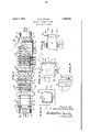
- FIG. 1 is a side elevation, partly in section, of my improved pattern cylinder
- Fig. 2 is a sectional end view, taken along the line 22 in Fig. 1;
- Fig. 3 is an end view, looking in the direction of the arrow 3 in Fig. 1;
- Fig. 4 is a detail sectional elevation, showing the manner in which the plates or partitions are assembled.
- Fig. 5 is an enlarged detail view, looking in the direction of the arrow 5 in Fig. 1.
- my improved pattern cylinder comprises a tubular supporting member 10, shown herein as a metal tube of rectangular cross section. Bearing heads 11 are fitted into the ends of the supporting member and are provided with the corner projections 12 for engagement by the usual feed pawl 13 (Fig. 3).
- Card engaging members 15 are slidable on the member 10 and support the Side edges ofthe pattern cards G; These members 15 are provided with conical studs 16 which enter enlarged perforations along the'side' edges'of the cards and accurately position the cards'on the cylinder.
- the members'15 are provided with hub portions. 17 slotted to receive binding screws 18 by which the mem-. bers 15 may be secured on the supporting member 10 in axially adjusted position.-
- a plurality of partition members 20 are mounted between each pair of card-engaging members 15 and supportthe pattern cards closely adjacent to the perforations therein and to the paths of movement of thejacquard needles.
- Each partition member 20 has a rectangular opening .22 therein and is also provided with flanges 23 at the sidesof of less height than the distance between adjacent faces of the partition members when assembled.
- I first provide the outer surface of the rectangular tube 10 with a coating of tin or of a low melting alloy or solder, and I similarly coat the partition members 20 and particularly the parts. therof adjacent the central openings 22. I then assemble the partition members on the tube 10 and accurately position them in their desired axial spacing, as by the use of a slotted gauge bar or index 30 (Fig. 4). I
- a jacquard pattern cylinder comprisingwa non-circular supportinginember, and a'plunality of sheet metal partition members mounted thereon and firmly secured thereto in accurately spaced relation, said partition members having non-circular central open-- ings and having portions of material adjacent said openings ottset to form -fl'ange's snugly engaging said supporting member, said flanges being of less height than the distance between adjacent partition members when asembled.
- a jacquard pattern cylinder comprising a supporting member, and a plurality of partition members having flanged bearing ortions snugly fitting over said supporting member, said partition members being permanently secured to said supporting member in accurately spaced relation, and the flanged bearing portions of said partition members 1 being spaced and out of contact with-each
Landscapes
- Engineering & Computer Science (AREA)
- Textile Engineering (AREA)
- Preliminary Treatment Of Fibers (AREA)
Description
April 5, 1932. E. R. HOLMES JACQUARD PATTERN CYLINDER Filed Dec. 19, 1930 MT I J'Nl/EA/TUR 4 amuse RHULMES A 77'0PNE Y5 Patented Apr. 5, 1932 ET TES PATENT? QFFEIE LE'EIDGE R. HOLMES, E WonoES'TER, MASSACHUSETTS, AssIGnoE. To cnoMrToN & KNOWLES LooM' WORKS, or WORCESTER, MASSACHUSETTS, A CORPORATION or MASSACHUSETTS JACQUARD PATTERN ,CYIiINDER Application filed December 19, 1930. Serial No. 503,504.
This invention relates to a cylinder for supporting pattern cards in a Jacquard loom. Such cylinders are usually rectangular or polyangular in cross section, and each flat side or face of the cylinder must be so constructed that the jacquard needles may pass freely through the perforations in the pattern cards. It is also necessary that the cards be firmly supported closely adjacent the paths of the needles, so that they may firmly resist the pressure of the needleswhere no perforations occur.
It is the general object of my invention to provide an improved construction for such a pattern cylinder, permitting the cylinder to be economically manufactured, and giving it the necessary accuracy for use with closely adjacent needles.
In the preferred form, my improved cylinder comprises a plurality of metal plates or partitions mounted on a non-circular supporting member and secured thereon in accurately spaced relation.
My invention further relates to arrangements and combinations of parts which will be hereinafter described and more particularly pointed out in the appended claims.
A preferred form of the invention is shown in the drawings, in which Fig. 1 is a side elevation, partly in section, of my improved pattern cylinder;
Fig. 2 is a sectional end view, taken along the line 22 in Fig. 1;
Fig. 3 is an end view, looking in the direction of the arrow 3 in Fig. 1;
Fig. 4 is a detail sectional elevation, showing the manner in which the plates or partitions are assembled; and
Fig. 5 is an enlarged detail view, looking in the direction of the arrow 5 in Fig. 1.
Referring to the drawings, my improved pattern cylinder comprises a tubular supporting member 10, shown herein as a metal tube of rectangular cross section. Bearing heads 11 are fitted into the ends of the supporting member and are provided with the corner projections 12 for engagement by the usual feed pawl 13 (Fig. 3).
A plurality of partition members 20 are mounted between each pair of card-engaging members 15 and supportthe pattern cards closely adjacent to the perforations therein and to the paths of movement of thejacquard needles. Each partition member 20 has a rectangular opening .22 therein and is also provided with flanges 23 at the sidesof of less height than the distance between adjacent faces of the partition members when assembled.
In assembling the partition members on the supporting member or tube 10, I preferably proceed'as follows:
' I first provide the outer surface of the rectangular tube 10 with a coating of tin or of a low melting alloy or solder, and I similarly coat the partition members 20 and particularly the parts. therof adjacent the central openings 22. I then assemble the partition members on the tube 10 and accurately position them in their desired axial spacing, as by the use of a slotted gauge bar or index 30 (Fig. 4). I
Y When the parts are thus assembled, I heat the partition members-20 and tube 10 in some convenient manner, as by directing heat-ed air or gas through the tube 10, until-the temperature of the parts israised sufficiently to melt the tin or solder coating between the engaging parts of the tube 10 and members 20. 'After the tin or solder is melted, the parts are allowed to coolwhile still retained in accurate spacing. Upon cooling, the parts are found to be firmly secured together and in the exact desired positions. The gauge 30 may if desired be removed after the partitions are assembled, and before the heating operation. In. this case, the partitions will be held in assembled relation by friction on the tube 10,.
By: making the flanges, 23 of less height than the spacing between the members 20, and by positioning all of the members by reference to a standard gauge baras. 80 instead of by gauging each partition member from its adjacent member, I avoid any accumulation of errors and produce a pattern cylinder in which all of the partitions are accurately located. Tliisis'of great importance, as the needles in fine jacquards are very closely spaced and a variation of a thirtyse'cond of an inch the'position of a partition mem-.
. ber may render the whole mechanism inoperative- The provision of the slotted hubs of the card-engaging members 15 and the adjusting 7 screws 1 8v is also of importance, as it permits accurate adjustment of the card engaging members with reference to the cards and also with re' ference to the partition members 20.
Having thus described my invention and the advantages thereof, I do not wish to be limited to the detailsherein disclosed, other wise than as set forth in "the claims,but what I claim is 1. A jacquard pattern cylinder comprisingwa non-circular supportinginember, and a'plunality of sheet metal partition members mounted thereon and firmly secured thereto in accurately spaced relation, said partition members having non-circular central open-- ings and having portions of material adjacent said openings ottset to form -fl'ange's snugly engaging said supporting member, said flanges being of less height than the distance between adjacent partition members when asembled.
2. The method of forminga jacquard pattern cylinder which consists in coating anoncircnla-r tube with a low melting metal, providing a plurality of partition members having' flamed central openings snugly fitting placing said partition members on the core with the flanges extending along and in frictlonal contact with the core, accurately positioning the members longitudinally of the core while maintaining them out of contact with each other, and subsequentlysecuring the members to the core while in frictional contact therewith.
,4. A jacquard pattern cylinder comprising a supporting member, and a plurality of partition members having flanged bearing ortions snugly fitting over said supporting member, said partition members being permanently secured to said supporting member in accurately spaced relation, and the flanged bearing portions of said partition members 1 being spaced and out of contact with-each
Priority Applications (1)
| Application Number | Priority Date | Filing Date | Title |
|---|---|---|---|
| US503504A US1852082A (en) | 1930-12-19 | 1930-12-19 | Jacquard pattern cylinder |
Applications Claiming Priority (1)
| Application Number | Priority Date | Filing Date | Title |
|---|---|---|---|
| US503504A US1852082A (en) | 1930-12-19 | 1930-12-19 | Jacquard pattern cylinder |
Publications (1)
| Publication Number | Publication Date |
|---|---|
| US1852082A true US1852082A (en) | 1932-04-05 |
Family
ID=24002365
Family Applications (1)
| Application Number | Title | Priority Date | Filing Date |
|---|---|---|---|
| US503504A Expired - Lifetime US1852082A (en) | 1930-12-19 | 1930-12-19 | Jacquard pattern cylinder |
Country Status (1)
| Country | Link |
|---|---|
| US (1) | US1852082A (en) |
Cited By (2)
| Publication number | Priority date | Publication date | Assignee | Title |
|---|---|---|---|---|
| DE1112710B (en) * | 1958-06-21 | 1961-08-10 | Schruender & Cramer | Verdol jacquard machine with a jacquard card with reinforcement strips on one side in the longitudinal direction in the area of the nipple holes and a method for producing the jacquard card |
| DE1169379B (en) * | 1958-06-30 | 1964-04-30 | Erhard Kenk | Verdol jacquard machine with jacquard card |
-
1930
- 1930-12-19 US US503504A patent/US1852082A/en not_active Expired - Lifetime
Cited By (2)
| Publication number | Priority date | Publication date | Assignee | Title |
|---|---|---|---|---|
| DE1112710B (en) * | 1958-06-21 | 1961-08-10 | Schruender & Cramer | Verdol jacquard machine with a jacquard card with reinforcement strips on one side in the longitudinal direction in the area of the nipple holes and a method for producing the jacquard card |
| DE1169379B (en) * | 1958-06-30 | 1964-04-30 | Erhard Kenk | Verdol jacquard machine with jacquard card |
Similar Documents
| Publication | Publication Date | Title |
|---|---|---|
| US2759271A (en) | Contour gauges | |
| US1852082A (en) | Jacquard pattern cylinder | |
| US3355206A (en) | Suspension grid for ceilings | |
| US2357070A (en) | File folder and index tab construction | |
| US2708455A (en) | Loom harness | |
| US2145708A (en) | Flexible tray for carburizing furnaces | |
| US2198529A (en) | Heat exchanger | |
| US2189652A (en) | Finned tube | |
| US850892A (en) | Music-roll for mechanical musical instruments. | |
| US2487409A (en) | Doctor blade and mounting | |
| US2511822A (en) | Loom harness | |
| US2443522A (en) | Index card and signal | |
| US2303882A (en) | Tray for heat treating furnaces and the like | |
| US2210099A (en) | Cash register | |
| US3097614A (en) | Table extension slide mechanism | |
| US1794775A (en) | Pin board | |
| US1981367A (en) | Radiator | |
| US1725004A (en) | Heddle frame | |
| JP6516177B1 (en) | Column-type inking ruler | |
| US1321351A (en) | anderson | |
| US3430346A (en) | Sewing gauge | |
| US3120058A (en) | Device and method for laying out patterns | |
| NO125065B (en) | ||
| US2487968A (en) | Thermally responsive unit | |
| US2794215A (en) | Replaceable bearing elements for cap bars of drafting machines |