US1852076A - Gauge harness - Google Patents
Gauge harness Download PDFInfo
- Publication number
- US1852076A US1852076A US501104A US50110430A US1852076A US 1852076 A US1852076 A US 1852076A US 501104 A US501104 A US 501104A US 50110430 A US50110430 A US 50110430A US 1852076 A US1852076 A US 1852076A
- Authority
- US
- United States
- Prior art keywords
- harness
- gauge
- bars
- thumbscrews
- motion
- Prior art date
- Legal status (The legal status is an assumption and is not a legal conclusion. Google has not performed a legal analysis and makes no representation as to the accuracy of the status listed.)
- Expired - Lifetime
Links
- 238000010276 construction Methods 0.000 description 2
- 210000003813 thumb Anatomy 0.000 description 2
- 210000000481 breast Anatomy 0.000 description 1
- 230000004048 modification Effects 0.000 description 1
- 238000012986 modification Methods 0.000 description 1
- 239000004753 textile Substances 0.000 description 1
Images
Classifications
-
- D—TEXTILES; PAPER
- D03—WEAVING
- D03C—SHEDDING MECHANISMS; PATTERN CARDS OR CHAINS; PUNCHING OF CARDS; DESIGNING PATTERNS
- D03C9/00—Healds; Heald frames
- D03C9/06—Heald frames
- D03C9/0608—Construction of frame parts
-
- D—TEXTILES; PAPER
- D03—WEAVING
- D03C—SHEDDING MECHANISMS; PATTERN CARDS OR CHAINS; PUNCHING OF CARDS; DESIGNING PATTERNS
- D03C9/00—Healds; Heald frames
- D03C9/06—Heald frames
- D03C9/0666—Connection of frame parts
-
- D—TEXTILES; PAPER
- D03—WEAVING
- D03C—SHEDDING MECHANISMS; PATTERN CARDS OR CHAINS; PUNCHING OF CARDS; DESIGNING PATTERNS
- D03C9/00—Healds; Heald frames
- D03C9/06—Heald frames
- D03C9/0683—Arrangements or means for the linking to the drive system
Definitions
- This invention relates to a gauge harness to facilitate the positioning of harness connections during the assembly of looms.
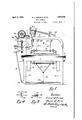
- Fig. 1 is a front elevation of a loom in which our invention is employed
- Fig. 2 is a sectional plan view looking in the direction of arrow 2, Fig. 1,
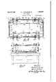
- Fig. 3 is a vertical section along lines 3-3 on Fig. 2,
- Fig. 4 is a vertical section through the heddle bar along line 44, Fig. 3, and
- Fig. 5 is a horizontal section along line 55, Fig. 3.
- loomsides 10 supporting the breast beam 11.
- the lay L is supported by the usual lay swords 12 and receives its forward and rearward motion through a pair of crank connectors 13 from a crank shaft 14, as shown in Fig. 2.
- a Knowles head designated at 15 and supported by the loomside 10 and arch stand 16.
- the head receives its motion from a vertical shaft 17 by means of bevel gears 18 which actuate cylinder gears 19 and 20.
- Connecting levers 21 when acted upon by the pattern mechanism on the pattern cylinder 22 are moved by the cylinder gears to cause angular motion is made by means of cords 34 and 35.
- jacks thus
- the harness jacks J havelower arms connected to cords 31 passing around pulley sheaves 32 and 33 and thence'to the lower side of the gauge harness, where connection The provide positive motion in both directions. 7
- the gauge is designated generally at G and is provided with an upper tubular bar36 with a bore 37 which receives the horizontal ends 38 of angle rods 40.
- a lower tubular bar 41 similar to the upper bar '36 is provided being with a bore 42 to receive the ends 43 of lower position with regard to the tubes 45 and'46 8 5 by means of thumb screws 47
- the thumb screws are held by collars 48 and project through the tubes to exert pressure on the angle rods'and hold them fixed.
- the lower angle rods 44' are held in fixed position' in the tubes 45 and 46 by means of rivets 49 and 50.
- The'upper and lower tubular bars 36 and 41 are provided collars 51 which support books 52 formed integral therewith. As shown in Figs.” 4 and 5 the hooks 52 have upturned ends 53 which form slots 54 to receive the heddlebars. 55. The hedolle bars 1 are prevented from sliding out of the hooks by means of bentover ends56. Thumbscrews 57 similar to 47 are tapped through the collars 51 and exert pressure on their re spective angle rods. It can thus be seen that the thumbscrews 57 act to hold the heddlebars, the tubes, and the angle roes in fixed relation to each other. As the hooks 52 on the lower bar are inverted the lower heddle bar 55. would naturally fall out of position were it not for the heddles H which may be strung on the bars in any desired number.
- Collars 58 carrying hooks 59rnay be slidably mounted on both upper and lower tubular bars.
- Thumbscrews 60 similar to thumbscrews 47 and 57 may be employed to hold the collars 58 in any desirable position longitudinally ofthe bars.
- the head 15. may be turned by hand with thewheel 61 .tocausethe jacks J to lift or lower the harness gauge and thus determine the maximum shed opening.
- gauge harness or dummy harness comprises adjustable parts, preferabl'y telescoping, which permit the height and length to be Varied as required;
Landscapes
- Engineering & Computer Science (AREA)
- Textile Engineering (AREA)
- Preliminary Treatment Of Fibers (AREA)
Description
E J. FERNANE ET AL April 5, 1932.
GAUGE HARNESS Filed Dec. 9, 1930 2 Sheets-Sheet l 5( lire/250m Edward (IE/wove Mar/'06 I! fZ/mn April 1932- E. J. FERNANE ET'AL GAUGE HARNESS Filed Dec. 9, 1930 2 Sheets-Sheet 2 w m M ra 0+ L wl f mmlmw WM 5 ,U H v 2. L w
' Patented Apr. 5, 1932 UNETED STATES PATENT OFFICE EDWARD J. FERNANE AND MAURICE J. FLYNN, OF WORCESTER, MASSACHUSETTS, AS:
SIGNORS TO CROMPTON KNOWLES LOOM WORKS, F WORCESTER; MASSACH'U SETTS, A CORPORATION OF MASSACHUSETTS V I i Y Gar Jen HARNESS Application filed December 9, 1930. Serial No. 501,104.
This invention relates to a gauge harness to facilitate the positioning of harness connections during the assembly of looms.
It frequently happens that the manufac- -.turer of textile looms does not make the harnesses that are to be used in them. The purchaser, when placing his order, specifies the size of the harness to be used and the loom is made accordingly. During the assembly of the looms it is desirable to check the accuracy of the Various harness connections, but it often happens that a harness of the required size is not available. It is an object of our invention to provide a dummy harness which may be adjusted to any desired dimensions for the purpose of checking the harness connections.
Vith this and other objects in view which will appear as the description proceeds, our
invention relates to the combination and arrangement of parts hereinafter described and set forth in the claim.
In the accompanying drawings, wherein a convenient embodiment of our invention is set forth,
Fig. 1 is a front elevation of a loom in which our invention is employed,
Fig. 2 is a sectional plan view looking in the direction of arrow 2, Fig. 1,
Fig. 3 is a vertical section along lines 3-3 on Fig. 2,
Fig. 4 is a vertical section through the heddle bar along line 44, Fig. 3, and
Fig. 5 is a horizontal section along line 55, Fig. 3.
Referring to the drawings, we have shown loomsides 10 supporting the breast beam 11. The lay L is supported by the usual lay swords 12 and receives its forward and rearward motion through a pair of crank connectors 13 from a crank shaft 14, as shown in Fig. 2.
For purposes of illustration we show a Knowles head designated at 15 and supported by the loomside 10 and arch stand 16. The head receives its motion from a vertical shaft 17 by means of bevel gears 18 which actuate cylinder gears 19 and 20. Connecting levers 21 when acted upon by the pattern mechanism on the pattern cylinder 22 are moved by the cylinder gears to cause angular motion is made by means of cords 34 and 35. jacks thus The harness jacks J havelower arms connected to cords 31 passing around pulley sheaves 32 and 33 and thence'to the lower side of the gauge harness, where connection The provide positive motion in both directions. 7
The matter thus far described is of common construction and forms no part of our 5 present invention. 7
In carrying our invention into effectwe provide a dummy harness shown more clearly in Fig. 3 which may be placed in the loo m to check the previously described harness actuating'mechanism while the loom is assembled; Y
The gauge is designated generally at G and is provided with an upper tubular bar36 with a bore 37 which receives the horizontal ends 38 of angle rods 40. A lower tubular bar 41 similar to the upper bar '36 is provided being with a bore 42 to receive the ends 43 of lower position with regard to the tubes 45 and'46 8 5 by means of thumb screws 47 The thumb screws are held by collars 48 and project through the tubes to exert pressure on the angle rods'and hold them fixed. The lower angle rods 44'are held in fixed position' in the tubes 45 and 46 by means of rivets 49 and 50. r j
The'upper and lower tubular bars 36 and 41 are provided collars 51 which support books 52 formed integral therewith. As shown in Figs." 4 and 5 the hooks 52 have upturned ends 53 which form slots 54 to receive the heddlebars. 55. The hedolle bars 1 are prevented from sliding out of the hooks by means of bentover ends56. Thumbscrews 57 similar to 47 are tapped through the collars 51 and exert pressure on their re spective angle rods. It can thus be seen that the thumbscrews 57 act to hold the heddlebars, the tubes, and the angle roes in fixed relation to each other. As the hooks 52 on the lower bar are inverted the lower heddle bar 55. would naturally fall out of position were it not for the heddles H which may be strung on the bars in any desired number.
.In. making practical use of our invention 7 the upper and lower thumbscrews 57 are modate the heddle.
loosened and the angle rods 40 and 44 moved outwardly away from the center of the frame Having thus described our invention it will be seen that changes and modifications may be made therein by those skilled in the art without departing from the spirit and scope of the invention and we do not. wish to be limited to the details herein disclosed, but what we claim is:
In a gauge harness for looms having har ness connections, a pair of crossmembers, a
to increase its width to any desired dimen- V sion. Several heddles H ofthe required size are then strung along the heddle bars 55. The thumbscrews 47 on the vertical tubular bars 45 and 46 are then loosened to allow the frame tobe adjusted to the proper height and to position the heddle bars toaccom- Heddles of different lengths are to. be used with various vertical adjustments.
The-,thumbscrews are then loosened and the hooks 59 are adjusted longitudinally on the tubular bars 36' and 41. It will be understood that there will be certain positions on the bars wherethe forces of the harness cords 24, 2'5, 34 and 35 will be most efficiently distributed to the harness frame.v
By placingthis harness gauge in the loom I and. supporting it by means of the harness Cords 24,25. and 31 the properlocation of the pulley sheaves 28 and 29 on the arch stand 16' may be-determin-ed as well as the maximum available-distance betweenv the crank connectors. 13, which are located opposite both. ends I 0i? the harnesses.
By placing the gauge as far forward as possible without interferri'ng with the rear- Ward motion ofthe lay L as shown in Fig. 2 and as far to the rear as possible without interferring with the motion of the crank shaft, 14 We may determine the maximum depth of the space to be used for harnesses.
The head 15. may be turned by hand with thewheel 61 .tocausethe jacks J to lift or lower the harness gauge and thus determine the maximum shed opening.
Fromthe foregoing it will be seenthat we have provided means whereby looms may be tested-for all ordinary harness problems during construction, without the necessity of keeping various harnesses on hand. It. will be seenalso that the gauge harness or dummy harness comprises adjustable parts, preferabl'y telescoping, which permit the height and length to be Varied as required;
Priority Applications (1)
| Application Number | Priority Date | Filing Date | Title |
|---|---|---|---|
| US501104A US1852076A (en) | 1930-12-09 | 1930-12-09 | Gauge harness |
Applications Claiming Priority (1)
| Application Number | Priority Date | Filing Date | Title |
|---|---|---|---|
| US501104A US1852076A (en) | 1930-12-09 | 1930-12-09 | Gauge harness |
Publications (1)
| Publication Number | Publication Date |
|---|---|
| US1852076A true US1852076A (en) | 1932-04-05 |
Family
ID=23992154
Family Applications (1)
| Application Number | Title | Priority Date | Filing Date |
|---|---|---|---|
| US501104A Expired - Lifetime US1852076A (en) | 1930-12-09 | 1930-12-09 | Gauge harness |
Country Status (1)
| Country | Link |
|---|---|
| US (1) | US1852076A (en) |
Cited By (4)
| Publication number | Priority date | Publication date | Assignee | Title |
|---|---|---|---|---|
| DE747390C (en) * | 1938-03-09 | 1944-09-22 | Tefag Textil Finanz Ag | Heald shaft driven from below without an upper fixed shaft rod |
| US2692619A (en) * | 1948-12-21 | 1954-10-26 | Froehlich A G E | Heddle frame for looms |
| US3406726A (en) * | 1965-09-01 | 1968-10-22 | Sulzer Ag | Heddle frame |
| CN105803622A (en) * | 2016-06-06 | 2016-07-27 | 江苏宋和宋智能科技有限公司 | Heddle frame fixed shedding method and built-in mechanical device |
-
1930
- 1930-12-09 US US501104A patent/US1852076A/en not_active Expired - Lifetime
Cited By (4)
| Publication number | Priority date | Publication date | Assignee | Title |
|---|---|---|---|---|
| DE747390C (en) * | 1938-03-09 | 1944-09-22 | Tefag Textil Finanz Ag | Heald shaft driven from below without an upper fixed shaft rod |
| US2692619A (en) * | 1948-12-21 | 1954-10-26 | Froehlich A G E | Heddle frame for looms |
| US3406726A (en) * | 1965-09-01 | 1968-10-22 | Sulzer Ag | Heddle frame |
| CN105803622A (en) * | 2016-06-06 | 2016-07-27 | 江苏宋和宋智能科技有限公司 | Heddle frame fixed shedding method and built-in mechanical device |
Similar Documents
| Publication | Publication Date | Title |
|---|---|---|
| US1852076A (en) | Gauge harness | |
| US1545904A (en) | Loom harness | |
| US2242210A (en) | Hand loom | |
| US2107004A (en) | Device for warp leasing | |
| US2083291A (en) | Mechanism for the working and regulation of the healds course | |
| US380118A (en) | Assigistoe to the | |
| US2125278A (en) | Twine heddle | |
| US1786684A (en) | Temple for double-fabric looms | |
| US1582421A (en) | Harness motion for looms | |
| US1803539A (en) | Harness mechanism for looms | |
| US2113492A (en) | Means for the manufacture of fabrics with bias weft | |
| US1281065A (en) | Spring-stand for looms. | |
| US2087332A (en) | Loom | |
| US2524670A (en) | Reed beatup mounting for loom lays | |
| US2860664A (en) | Method of and apparatus for weaving high and low pile fabrics | |
| US1697645A (en) | Harness for reed-weaving looms | |
| US1568020A (en) | Marquisette or cross weaving loom | |
| US1718816A (en) | Loom | |
| US1594618A (en) | Harness head motion for looms | |
| US1672773A (en) | Attachment for dobby looms | |
| US1719476A (en) | Jacquard-loom harness | |
| US2058129A (en) | Shedding mechanism for looms | |
| US1632472A (en) | Warp-end holder for warp beams | |
| US1595271A (en) | Harness motion for looms | |
| US1294809A (en) | Warp-controlling device for looms. |