US1852075A - Wrench - Google Patents
Wrench Download PDFInfo
- Publication number
- US1852075A US1852075A US542168A US54216831A US1852075A US 1852075 A US1852075 A US 1852075A US 542168 A US542168 A US 542168A US 54216831 A US54216831 A US 54216831A US 1852075 A US1852075 A US 1852075A
- Authority
- US
- United States
- Prior art keywords
- jaw
- wrench
- head
- slidable
- work
- Prior art date
- Legal status (The legal status is an assumption and is not a legal conclusion. Google has not performed a legal analysis and makes no representation as to the accuracy of the status listed.)
- Expired - Lifetime
Links
- 210000003813 thumb Anatomy 0.000 description 6
- 238000010276 construction Methods 0.000 description 3
Images
Classifications
-
- B—PERFORMING OPERATIONS; TRANSPORTING
- B25—HAND TOOLS; PORTABLE POWER-DRIVEN TOOLS; MANIPULATORS
- B25B—TOOLS OR BENCH DEVICES NOT OTHERWISE PROVIDED FOR, FOR FASTENING, CONNECTING, DISENGAGING OR HOLDING
- B25B13/00—Spanners; Wrenches
- B25B13/48—Spanners; Wrenches for special purposes
- B25B13/50—Spanners; Wrenches for special purposes for operating on work of special profile, e.g. pipes
- B25B13/5008—Spanners; Wrenches for special purposes for operating on work of special profile, e.g. pipes for operating on pipes or cylindrical objects
- B25B13/5016—Spanners; Wrenches for special purposes for operating on work of special profile, e.g. pipes for operating on pipes or cylindrical objects by externally gripping the pipe
- B25B13/5025—Spanners; Wrenches for special purposes for operating on work of special profile, e.g. pipes for operating on pipes or cylindrical objects by externally gripping the pipe using a pipe wrench type tool
- B25B13/5041—Spanners; Wrenches for special purposes for operating on work of special profile, e.g. pipes for operating on pipes or cylindrical objects by externally gripping the pipe using a pipe wrench type tool with movable or adjustable jaws
- B25B13/5058—Linearly moving or adjustable, e.g. with an additional small tilting or rocking movement
-
- Y—GENERAL TAGGING OF NEW TECHNOLOGICAL DEVELOPMENTS; GENERAL TAGGING OF CROSS-SECTIONAL TECHNOLOGIES SPANNING OVER SEVERAL SECTIONS OF THE IPC; TECHNICAL SUBJECTS COVERED BY FORMER USPC CROSS-REFERENCE ART COLLECTIONS [XRACs] AND DIGESTS
- Y10—TECHNICAL SUBJECTS COVERED BY FORMER USPC
- Y10S—TECHNICAL SUBJECTS COVERED BY FORMER USPC CROSS-REFERENCE ART COLLECTIONS [XRACs] AND DIGESTS
- Y10S81/00—Tools
- Y10S81/05—Wrench scales and indicia
Definitions
- Another important obj ect of the invention is to provide a wrench of the aforementioned character embodying a slidable outer jaw and further including means through the medium of which the slidable jaw may be expeditiously adjusted to any desired position without the necessity for applying the wrench to the work.
- Fig. 2 is a view in front elevation showing a ortion of the wrench.
- ig. 3 is a view in vertical section through a portion of the wrench.
- Fig. 4 is across sectional view takenrsubstaiiti'ally on the line 4 4 of Fig. 3.
- Fig. 5 is a detailed view in front elevation of the pivoted jaw.
- Fig. 6 is a detail view in bottom plan of the slidable thumb piece or member.
- Fig. 7 is a detail view of the link which slidably connects the pivoted jaw with the slidable member for actuation thereby.
- the numeral 1 designates an elongated, 'tubular handle ⁇ which Y closed one ⁇ .end and which' is open. atfifts otherv end. ⁇ Fixed on ⁇ the end portion. of. the handle 1 which is hollow, is a head Zhaving.
- 3.' -A bore 4 extends, lon-. gi-tudi-nally inthe head '2, from one side of ⁇ the opening 3 for the reception of the hand-le l. lheliead 2 is further provided, with a comparatively small bore 5 which is a'lined witlrtlie bore 4 and which extends longitudinally in the head from the other side of the opening 3.
- the reference Vnumeral 6 designates an outer slidable jaw having-a concave, toothed Work engaging face 7.
- the .slidable jaw i is Vformed integrally with a ⁇ shank which f ineueles emeeth. portion 8, and a. threaded' free wend' portion 9..
- the shank ofthe jaw 6 is operable in the bere 5 and: the. :handle 1 eind the threaded portion @et seid; shank raverses the opening 3 and has thlifeadedly meunteei thereeli eed. rotatably .-Cleieeeedin the Opening knefled ediuetllg met. l0,
- the smeeth portion 8 of the 'Shank is pref. videdv with esce-1ev 11.011 et leest one.v Side l ⁇ thereof.
- head 2 further includes a Tholiow ppition 1,2 ⁇ having. 'ieelinefv forward Well 13 mended/With ale-neeudinel slet 14- Aperftee l2 eztlie heed-21S enen et its.
- a .thumb nephew 1S is slidably. ⁇ mounted-on the ier/Hee@ veellle the ieed'a eed has extending theeefrQmL en erm 12 whichV is epeeable in :tlieslot 14 and'which .extendsdnto lie-'hellen nettime@ ef elle head2, and 'eermeeteeie e @evenwel-1y.direeeedlheek mea ⁇ lee"
- coiled spring 25 has one end anchored to the head 2.and its other end connected with the hook 20 for yieldinglyv urging the swinging jaw 15 toward its operative orwork engag- ⁇ ing position. course, disposed in the hollow portion l2 of the head 2.
- the sliding jaw 6 may be expeditiously adjusted to the desired position through the medium of the adjustingnut 10 v by observing the scale 11 relative to the free end of the head 2, as will be obvious.
- the slidable jaw 6 may be adjusted substantially to the desired position without the necessity 'for applying :the tool to the work.
- the thumb piece 18 is moved downwardly against the tension of the lcoiled spring. 25 to'swing the jaw 15 away from the jaw 6.
- the tool is then applied to the work and the thumb piece 18 is released, after which thev coiled spring 25 will swing the jaw 15 against the work.
- the handle 1 is swung or moved from left to right as the tool is viewed in Figs. 1 and 3 of the drawings, the jaw 15 functions as a cam and rigidly grips the pipe and the greater the force or power applied to the handle l, the tighter the pipe or other object will be gripped.
- a vwrench comprising av handle,v a head fixed on one end portion to the handleand having a hollow portion, said head further having an inclined wall having a longitudinal slot therein, a slidable jaw mounted on the head, means for adjusting the slidable jaw, a pivoted jaw eccentrically mounted in the hollow portion of the head and projecting therefrom in opposed relation to the first-named jaw for co-action with said firstnamed jaw, a thumb piece mounted for slid# Ving movement on the inclined wall of theY head, an larm-Yon thethumb piece operable in f the slot and extending into thehollow portion of theihead, a hook on the free end of the arm, va link operatively connecting the pivoted jaw to the arms for actuation by the thumlriv piece, and a coiled spring mounted in the hollow portion of the head and having ⁇ one end anchored thereto and its other end connected to the hook for yieldingly urging the pivoted jaw toward its work-engaging position.
Landscapes
- Engineering & Computer Science (AREA)
- Mechanical Engineering (AREA)
- Details Of Spanners, Wrenches, And Screw Drivers And Accessories (AREA)
Description
E. w. cRocKER 1,852,075
WRENCH Filed June 4, 1931 2 Sheets-Sheet l Inventor Homey April 5, 1932. E W, CROCKER 1,852,075
WRENCH Filed June 4, 1931 2 Sheets-Sheet 2 @Mmm f1 Homey Patented Apr. 5, 17932 UNITED STATES RAT-ENT cremes.:
ERNEST w. cnociznn, ci* Dfuciins'ivn, Imran.
WRENCH Application filed June 4, 1931.` Serial No.` 542,168.
embodying a novel construction and arrange-- ment of parts, through the medium of which the pipe or other object to which the tool is applied will he firmly gripped to prevent rotation of the wrench relative thereto.
Another important obj ect of the invention is to provide a wrench of the aforementioned character embodying a slidable outer jaw and further including means through the medium of which the slidable jaw may be expeditiously adjusted to any desired position without the necessity for applying the wrench to the work.
Other objects of the invention are to provide a wrench of the character described which will be simple in construction, strong, durable, compact, efficient and reliable in operation and which may be manufactured at low cost.
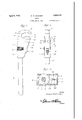
All of the foregoing and still further objects and advantages of the invention wil become apparent from a study of -the f ollowing speciiication, taken in connection with the accompanying drawings, wherein like characters of reference designate corresponding parts throughout the several views, and wherein Figure l is a view in side elevation showing a wrench constructed in accordance with the present invention.
Fig. 2 is a view in front elevation showing a ortion of the wrench.
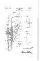
ig. 3 is a view in vertical section through a portion of the wrench.
Fig. 4 is across sectional view takenrsubstaiiti'ally on the line 4 4 of Fig. 3.
Fig. 5 is a detailed view in front elevation of the pivoted jaw.
Fig. 6 is a detail view in bottom plan of the slidable thumb piece or member.
Fig. 7 is a detail view of the link which slidably connects the pivoted jaw with the slidable member for actuation thereby.
Referring now to the drawings in detail, it will be seen that the numeral 1 designates an elongated, 'tubular handle` which Y closed one` .end and which' is open. atfifts otherv end. `Fixed on` the end portion. of. the handle 1 which is hollow, is a head Zhaving.
opposed openings: 3.' -A bore 4 extends, lon-. gi-tudi-nally inthe head '2, from one side of` the opening 3 for the reception of the hand-le l. lheliead 2 is further provided, with a comparatively small bore 5 which is a'lined witlrtlie bore 4 and which extends longitudinally in the head from the other side of the opening 3.
Y The reference Vnumeral 6 designates an outer slidable jaw having-a concave, toothed Work engaging face 7. (The .slidable jaw i is Vformed integrally with a` shank which f ineueles emeeth. portion 8, and a. threaded' free wend' portion 9.. The shank ofthe jaw 6 is operable in the bere 5 and: the. :handle 1 eind the threaded portion @et seid; shank raverses the opening 3 and has thlifeadedly meunteei thereeli eed. rotatably .-Cleieeeedin the Opening knefled ediuetllg met. l0,
The smeeth portion 8 of the 'Shank is pref. videdv with esce-1ev 11.011 et leest one.v Side l` thereof. head 2 further includes a Tholiow ppition 1,2` having. 'ieelinefv forward Well 13 mended/With ale-neeudinel slet 14- Aperftee l2 eztlie heed-21S enen et its. fel:- ward end and has mounted for svvigrigingV nievemeee .theeeee .i le which eieeeentrically mounted, as at 16, the hollow' pori tee- 12) et the .heed 2.,f1the swinging jew. v15 preieetiee 'berend they ierveerdf feed -Of .e1-ie heed2 The. iev legis-provided with efteethed e011-, YeXfwerk engaging ieee 17, the vteeth en the ien 1.5` being -eeneeitelv .depesed with respect to, those on .the `slidablejaw 6,.
A .thumb niece 1S is slidably.` mounted-on the ier/Hee@ veellle the ieed'a eed has extending theeefrQmL en erm 12 whichV is epeeable in :tlieslot 14 and'which .extendsdnto lie-'hellen nettime@ ef elle head2, and 'eermeeteeie e @evenwel-1y.direeeedlheek mea `lee" The foi-Werd; eideV @fthe .Swinging .i ev A1.5
efeeeeel7 ee efe :21- 1.11 mennen te provide e Hb 22. beilegen eperture theremi, for the reception fof-one ofthe trunnions 23a-on .thel
eedeef; e .eem-meting 111211524 which.; een'szi.-k
for in the arm 19 of the thumb piece 18. A
coiled spring 25 has one end anchored to the head 2.and its other end connected with the hook 20 for yieldinglyv urging the swinging jaw 15 toward its operative orwork engag-` ing position. course, disposed in the hollow portion l2 of the head 2.
In use, the sliding jaw 6 may be expeditiously adjusted to the desired position through the medium of the adjustingnut 10 v by observing the scale 11 relative to the free end of the head 2, as will be obvious. In this manner,-the slidable jaw 6 may be adjusted substantially to the desired position without the necessity 'for applying :the tool to the work. When the tool is to be applied to the work, the thumb piece 18 is moved downwardly against the tension of the lcoiled spring. 25 to'swing the jaw 15 away from the jaw 6. The tool is then applied to the work and the thumb piece 18 is released, after which thev coiled spring 25 will swing the jaw 15 against the work. Then, when the handle 1 is swung or moved from left to right as the tool is viewed in Figs. 1 and 3 of the drawings, the jaw 15 functions as a cam and rigidly grips the pipe and the greater the force or power applied to the handle l, the tighter the pipe or other object will be gripped.
lIt is believed that the many advantages of a wrench constructed in accordance with this invention will be readily understood,
and although the preferred embodiment of the inventionis as illustrated and described, it is to be understood that changes in the details of construction may be made which will fall within the scope ofthe invention as claimed(Y j i Having thus described my invention,"what I claim as new is:-
A vwrench comprising av handle,v a head fixed on one end portion to the handleand having a hollow portion, said head further having an inclined wall having a longitudinal slot therein, a slidable jaw mounted on the head, means for adjusting the slidable jaw, a pivoted jaw eccentrically mounted in the hollow portion of the head and projecting therefrom in opposed relation to the first-named jaw for co-action with said firstnamed jaw, a thumb piece mounted for slid# Ving movement on the inclined wall of theY head, an larm-Yon thethumb piece operable in f the slot and extending into thehollow portion of theihead, a hook on the free end of the arm, va link operatively connecting the pivoted jaw to the arms for actuation by the thumlriv piece, and a coiled spring mounted in the hollow portion of the head and having` one end anchored thereto and its other end connected to the hook for yieldingly urging the pivoted jaw toward its work-engaging position.
In testimony whereof I affix my signature.
ERNEST W. CROCKER.
The coiled spring 25'is, of"
Vse
Priority Applications (1)
| Application Number | Priority Date | Filing Date | Title |
|---|---|---|---|
| US542168A US1852075A (en) | 1931-06-04 | 1931-06-04 | Wrench |
Applications Claiming Priority (1)
| Application Number | Priority Date | Filing Date | Title |
|---|---|---|---|
| US542168A US1852075A (en) | 1931-06-04 | 1931-06-04 | Wrench |
Publications (1)
| Publication Number | Publication Date |
|---|---|
| US1852075A true US1852075A (en) | 1932-04-05 |
Family
ID=24162626
Family Applications (1)
| Application Number | Title | Priority Date | Filing Date |
|---|---|---|---|
| US542168A Expired - Lifetime US1852075A (en) | 1931-06-04 | 1931-06-04 | Wrench |
Country Status (1)
| Country | Link |
|---|---|
| US (1) | US1852075A (en) |
Cited By (1)
| Publication number | Priority date | Publication date | Assignee | Title |
|---|---|---|---|---|
| US2598650A (en) * | 1948-07-28 | 1952-05-27 | Seymour Smith & Son Inc | Snap lock pliers with unlocking lever |
-
1931
- 1931-06-04 US US542168A patent/US1852075A/en not_active Expired - Lifetime
Cited By (1)
| Publication number | Priority date | Publication date | Assignee | Title |
|---|---|---|---|---|
| US2598650A (en) * | 1948-07-28 | 1952-05-27 | Seymour Smith & Son Inc | Snap lock pliers with unlocking lever |
Similar Documents
| Publication | Publication Date | Title |
|---|---|---|
| US2606471A (en) | Pliers with interchangeable jaws | |
| US2370308A (en) | Self-locking pliers | |
| US2064381A (en) | Jar clamp | |
| US1852075A (en) | Wrench | |
| US1835943A (en) | Tool handle | |
| US2050102A (en) | Wrench | |
| US1534066A (en) | Extracting tool | |
| US1517302A (en) | Adjustable wrench | |
| US1754739A (en) | Screw-holding screw driver | |
| US2296119A (en) | Wheel and gear puller | |
| US1514017A (en) | Wrench | |
| US2361607A (en) | Plier wrench | |
| US1748887A (en) | Intermittent-grip device | |
| US2468465A (en) | Chuck for wood bit braces | |
| US731260A (en) | Wrench. | |
| US2463774A (en) | Pivoted inner jaw pipe wrench | |
| US1676507A (en) | Pipe wrench | |
| US281626A (en) | Half to the j | |
| US1299543A (en) | Artificial hand. | |
| US1359775A (en) | Automatic pipe-vise | |
| US599169A (en) | Pipe-wrench | |
| US1294135A (en) | Adjustable brush-grip. | |
| US1060513A (en) | Pipe-wrench. | |
| US1366532A (en) | Razor-sharpening device | |
| US615926A (en) | Pipe-wrench |