US1852028A - Sign apparatus - Google Patents
Sign apparatus Download PDFInfo
- Publication number
- US1852028A US1852028A US529906A US52990631A US1852028A US 1852028 A US1852028 A US 1852028A US 529906 A US529906 A US 529906A US 52990631 A US52990631 A US 52990631A US 1852028 A US1852028 A US 1852028A
- Authority
- US
- United States
- Prior art keywords
- chassis
- sign
- lamps
- casing
- sign apparatus
- Prior art date
- Legal status (The legal status is an assumption and is not a legal conclusion. Google has not performed a legal analysis and makes no representation as to the accuracy of the status listed.)
- Expired - Lifetime
Links
- 230000001360 synchronised effect Effects 0.000 description 5
- 239000011521 glass Substances 0.000 description 2
- 239000004020 conductor Substances 0.000 description 1
- 238000010276 construction Methods 0.000 description 1
- 238000010586 diagram Methods 0.000 description 1
- 238000005286 illumination Methods 0.000 description 1
- 230000004048 modification Effects 0.000 description 1
- 238000012986 modification Methods 0.000 description 1
- 238000009877 rendering Methods 0.000 description 1
- 239000012780 transparent material Substances 0.000 description 1
Images
Classifications
-
- G—PHYSICS
- G09—EDUCATION; CRYPTOGRAPHY; DISPLAY; ADVERTISING; SEALS
- G09F—DISPLAYING; ADVERTISING; SIGNS; LABELS OR NAME-PLATES; SEALS
- G09F13/00—Illuminated signs; Luminous advertising
Definitions
- Advertising by signs is very efiective and popular, but such signs are expensive, because 1 of the cost ofmanufacture and the cost of upkeep and operation.
- a further object is the provision of an animated sign which may beoperated by a small synchronous motor ofthe type used for electric clocks and which consume an inappreciable amount of power, thus rendering the operation of the sign economical.
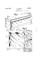
- Figure 1 represents a perspective view of the sign device.
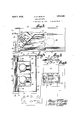
- Figure 2 represents a partial elevational View of the device, with parts broken away.
- Figure 3 represents a top view of the device with a part of the cover removed.
- Figure 4 represents a sectional view taken on line 44 of Figure 2.
- Figure 5 represents a view showing details of a cam operated switch used in the device.
- Figure 6 represents a Wiring diagram of the electrical circuit used in the device, and showing details of the cam operated switch.
- the sign device is shown to include a casing having a rear wall 10, side walls 11, a bottom 12 and a front wall 18 having aportion cut out to provide a window, the front wall being bevelled at 14 adj acent the edges of the window.
- the front wall At its upper edge the front wall has a right angled inwardly bent flange 17, which cooperates with a spaced angle 18, attached to the front wall to provide a support for the forand 40, and other structurehereinafter de- 1931.
- Theslots 6U 23 are of greater length than the width of the bars 22, the latter being of greater length than the space between the columns, so that when the bars are inserted in the slots and engage the upper heads 21, they are. securely held in position for the purpose of suspending the casmg. a 1
- angles 25 are attached to the front and side walls, each angle having a flange 26 adjacent the bevelled portions 14. Attached to the angles arechannels 27 and 28, spaced apart, so as to form with the flange 26,-four guideways, (see Figure 3) to receive, respectively, a sheet of glass 29, and a frame 30 upon which the advertising matter 1s carried, a second sheet of transparent glass'38, and finally, in channel 28, is" received the side edges of a chassis 34 which carries a plurality of incandescent lamps 3 9 scribed. V r w a
- the frame 30 is: provided 'withguideways into whichare slid strips 31' and32 which bear the advertising matter.
- the strips 3.1 and 32 may be of 'opaquemate-rialwith transparent figures thereon, or the strips-may be of transparent material with opaque figures thereon as may be desired.
- the chassis 34 is provided'with a centrally positioned shelf 35, on top and bottom members, all being trapezoidal in shape and connected by side walls 50, as shown in- Figure 3, the top and bottom members having ontturned flanges36 (see Figure 4).
- the shelf 35 divides the chassis into two compartments 37 and 88', in which are carried respectively a plurality of incandescent lamps 39 and 40, connected in series and respectively to conductors 46 and 45 of a switch device,
- reading matter on slide 31 is first displayed and will continue to be displayed during the displaying of the reading matter 011 slide 32, after which both displays simultaneously disappear.
- the switch and cam structure is mounted on a bracket 42, which together with the motor.41, is mounted on the side wall 50 of the chassis. It will be readily appreciated that this arrangement enables a convenient assemblyof the sign devices as the motor and all operating parts are compactly carried by the chassis, and the latter is independent of the casing, it being only necessary to slide the chassis into position in the channels 28. Obviously, in quantity production, the casing and associated parts may be constructed independently of the chassis, and the sign device completely assembled progressively in the manner in which automobiles are assembled in quantity production.
- the chassis as having but two compartments and. two sets of incandescent lamps, it may be readily constructed with three, four or morecompartments and sets of lamps, as may be desired without resort to invention, in order to'illuminate three, four or more it to be slidably positioned in a pair of the guideways, incandescent lamps mounted in the compartments of the chassis, a switching device to periodically make and break an'ele'ctrical circuit through the lamps, and a synchronous motor to actuate the switching device, said motor and switching device being mounted on the chassis.
- a casing having a column at each of its four corners, slots in said columns, a cross bar slidably positioned in the slots in each pair of columns,means on the columns to limit upward movement of the cross bars,,and a chain attached to the pended from above. 7
- a casing having a sis, incandescent lamps mounted on the chassis, means on the chassis to enable it to be slidably positioned in the guideways, and means mounted on the chassis to periodicalcross bars to enable the casing to be suspair of guideways mounted therein, a chasly make and break an electrical circuit through the lamps.
- the shelf 35Yobviously, prevents illumination of the slide 32 until the lamps 40 are lighted.
Landscapes
- Physics & Mathematics (AREA)
- General Physics & Mathematics (AREA)
- Engineering & Computer Science (AREA)
- Theoretical Computer Science (AREA)
- Audible And Visible Signals (AREA)
Description
April 1932- E. G. ROWLEY 1,852,028
' SIGN APPARATUS Filed April 14, 1931 2 Sheets-$heet 1 April 5, 1932.
E. G. ROWLEY S I GN APPARATUS Filed April 14, 1931 2 Sheets-Sheet 2 WMMWIMMM III/YIMWIIIMIIYIJ Hi: If
Patented Apr. 5, 1932 UNITED STATE-S PATENT OFFICE 1 EDWARD G. ROWLEY, F NEWARK, NEW JERSEY, ASSIGNOR TO CINE-A-GRAPH COR- PORATION, OF NEW YORK, N. Y.,
A oonrona'rronor DELAWARE SIGN. AFPABATUS 7 Application filed April 14,
to be more economically operated;
In the merchandising of commodities, advertising is an important and expensive item. Advertising by signs is very efiective and popular, but such signs are expensive, because 1 of the cost ofmanufacture and the cost of upkeep and operation. I
It is an object of this invention to provide a sign which may be readily constructed and assembled at a low cost.
A further object is the provision of an animated sign which may beoperated by a small synchronous motor ofthe type used for electric clocks and which consume an inappreciable amount of power, thus rendering the operation of the sign economical.
These and other advantageous objects, which will later appear, are accomplished by the simple and practical construction and arrangement of parts hereinafter described and l exhibited in the accompanying drawings,
forming part hereof, and in which:
Figure 1 represents a perspective view of the sign device.
Figure 2 represents a partial elevational View of the device, with parts broken away.
Figure 3 represents a top view of the device with a part of the cover removed.
Figure 4 represents a sectional view taken on line 44 of Figure 2. v
Figure 5 represents a view showing details of a cam operated switch used in the device.
Figure 6 represents a Wiring diagram of the electrical circuit used in the device, and showing details of the cam operated switch.
Referring to the drawings, the sign device is shown to include a casing having a rear wall 10, side walls 11, a bottom 12 anda front wall 18 having aportion cut out to provide a window, the front wall being bevelled at 14 adj acent the edges of the window.
At its upper edge the front wall has a right angled inwardly bent flange 17, which cooperates with a spaced angle 18, attached to the front wall to provide a support for the forand 40, and other structurehereinafter de- 1931. Serial No. 529,906.
ward edge of a slidable cover 15, which hasa downturned flange 16 at its rear edge to limit forward movement of the cover. The 1 side walls 11 are similarly provided with inturned flanges 19 which assist in guiding the cover 15.
casing to be suspended from above. Theslots 6U 23 are of greater length than the width of the bars 22, the latter being of greater length than the space between the columns, so that when the bars are inserted in the slots and engage the upper heads 21, they are. securely held in position for the purpose of suspending the casmg. a 1
At opposite sides of the window, angles 25 are attached to the front and side walls, each angle having a flange 26 adjacent the bevelled portions 14. Attached to the angles arechannels 27 and 28, spaced apart, so as to form with the flange 26,-four guideways, (see Figure 3) to receive, respectively, a sheet of glass 29, and a frame 30 upon which the advertising matter 1s carried, a second sheet of transparent glass'38, and finally, in channel 28, is" received the side edges of a chassis 34 which carries a plurality of incandescent lamps 3 9 scribed. V r w a The frame 30 is: provided 'withguideways into whichare slid strips 31' and32 which bear the advertising matter. The strips 3.1 and 32 may be of 'opaquemate-rialwith transparent figures thereon, or the strips-may be of transparent material with opaque figures thereon as may be desired. A, r
The chassis 34 is provided'with a centrally positioned shelf 35, on top and bottom members, all being trapezoidal in shape and connected by side walls 50, as shown in-Figure 3, the top and bottom members having ontturned flanges36 (see Figure 4).
The shelf 35 divides the chassis into two compartments 37 and 88', in which are carried respectively a plurality of incandescent lamps 39 and 40, connected in series and respectively to conductors 46 and 45 of a switch device,
-' having" spring fingers 44 and 43, normally in "100 y 7 It isobvious that while I have described break the circuit through bothsets of lamps.-
In this manner, reading matter on slide 31 is first displayed and will continue to be displayed during the displaying of the reading matter 011 slide 32, after which both displays simultaneously disappear.
- 'The' cams are fiXedto a shaft 47 which is driven by. a small synchronous motor 41 of the type commonly used for synchronous electric clocks and which consume an inappreciable-amount of power.; As far as I know, I am the first to adapt such a synchronous motor for use inrelectric sign apparatus and take advantage of the extremely low cost of operating such motors.
. The switch and cam structure is mounted on a bracket 42, which together with the motor.41, is mounted on the side wall 50 of the chassis. It will be readily appreciated that this arrangement enables a convenient assemblyof the sign devices as the motor and all operating parts are compactly carried by the chassis, and the latter is independent of the casing, it being only necessary to slide the chassis into position in the channels 28. Obviously, in quantity production, the casing and associated parts may be constructed independently of the chassis, and the sign device completely assembled progressively in the manner in which automobiles are assembled in quantity production.
the chassis as having but two compartments and. two sets of incandescent lamps, it may be readily constructed with three, four or morecompartments and sets of lamps, as may be desired without resort to invention, in order to'illuminate three, four or more it to be slidably positioned in a pair of the guideways, incandescent lamps mounted in the compartments of the chassis, a switching device to periodically make and break an'ele'ctrical circuit through the lamps, and a synchronous motor to actuate the switching device, said motor and switching device being mounted on the chassis.
2. In a sign device, a casing having a column at each of its four corners, slots in said columns, a cross bar slidably positioned in the slots in each pair of columns,means on the columns to limit upward movement of the cross bars,,and a chain attached to the pended from above. 7
3. In a sign device, a casing having a sis, incandescent lamps mounted on the chassis, means on the chassis to enable it to be slidably positioned in the guideways, and means mounted on the chassis to periodicalcross bars to enable the casing to be suspair of guideways mounted therein, a chasly make and break an electrical circuit through the lamps.
This specification signed this 13th day of April, 1931.
EDWARD e. ROWLEY.
strips bearing advertising matter. The shelf :35Yobviously, prevents illumination of the slide 32 until the lamps 40 are lighted.
From the above description, it is seen that I have provided a sign device which may be conveniently, readily and economically constructed, and which may be operated at an inappreciable cost. 7 I
. The foregoing disclosure is to be regarded H as descriptive and illustrative only,and not as restrictive or limitative of the invention, of which obviously an embodiment may be constructed including many modifications .-without departing from the general scope herein indicated and denoted in theappended i -Having thus described my invention, what w 7
Priority Applications (1)
| Application Number | Priority Date | Filing Date | Title |
|---|---|---|---|
| US529906A US1852028A (en) | 1931-04-14 | 1931-04-14 | Sign apparatus |
Applications Claiming Priority (1)
| Application Number | Priority Date | Filing Date | Title |
|---|---|---|---|
| US529906A US1852028A (en) | 1931-04-14 | 1931-04-14 | Sign apparatus |
Publications (1)
| Publication Number | Publication Date |
|---|---|
| US1852028A true US1852028A (en) | 1932-04-05 |
Family
ID=24111701
Family Applications (1)
| Application Number | Title | Priority Date | Filing Date |
|---|---|---|---|
| US529906A Expired - Lifetime US1852028A (en) | 1931-04-14 | 1931-04-14 | Sign apparatus |
Country Status (1)
| Country | Link |
|---|---|
| US (1) | US1852028A (en) |
Cited By (1)
| Publication number | Priority date | Publication date | Assignee | Title |
|---|---|---|---|---|
| US5423142A (en) * | 1993-10-19 | 1995-06-13 | The United States Of America As Represented By The Secretary Of The Army | Weather-proof, vandal-proof, changeable display sign |
-
1931
- 1931-04-14 US US529906A patent/US1852028A/en not_active Expired - Lifetime
Cited By (1)
| Publication number | Priority date | Publication date | Assignee | Title |
|---|---|---|---|---|
| US5423142A (en) * | 1993-10-19 | 1995-06-13 | The United States Of America As Represented By The Secretary Of The Army | Weather-proof, vandal-proof, changeable display sign |
Similar Documents
| Publication | Publication Date | Title |
|---|---|---|
| US5057977A (en) | Pull-out lighted display | |
| US1945072A (en) | Display apparatus | |
| US1852028A (en) | Sign apparatus | |
| US1120876A (en) | Sign. | |
| US3430371A (en) | Interleaved multiple sliding panel six-message display device | |
| US2112314A (en) | Advertising device | |
| US2193478A (en) | Electric sign | |
| US2271689A (en) | Illuminated display sign | |
| CN216849262U (en) | Advertisement display device convenient for replacing advertisement poster | |
| US2049929A (en) | Electric changeable exhibitor sign | |
| US2057465A (en) | Display device | |
| US1817397A (en) | Illuminated display | |
| US2365076A (en) | Illuminated sign | |
| US1740842A (en) | Display device | |
| US1572496A (en) | Sign | |
| US2405376A (en) | Advertising display device | |
| US2102798A (en) | Advertising device | |
| US1805209A (en) | Display device | |
| US1702497A (en) | craig | |
| US1839786A (en) | Illuminated sign | |
| US1971281A (en) | Display device | |
| US1744852A (en) | Advertising apparatus | |
| US2318596A (en) | Electric sign | |
| US1218231A (en) | Exhibition device. | |
| US1754242A (en) | Display device |