US1852015A - Machine for shaping shoe uppers - Google Patents
Machine for shaping shoe uppers Download PDFInfo
- Publication number
- US1852015A US1852015A US355566A US35556629A US1852015A US 1852015 A US1852015 A US 1852015A US 355566 A US355566 A US 355566A US 35556629 A US35556629 A US 35556629A US 1852015 A US1852015 A US 1852015A
- Authority
- US
- United States
- Prior art keywords
- wipers
- shoe
- margin
- tacks
- machine
- Prior art date
- Legal status (The legal status is an assumption and is not a legal conclusion. Google has not performed a legal analysis and makes no representation as to the accuracy of the status listed.)
- Expired - Lifetime
Links
- 238000007493 shaping process Methods 0.000 title description 7
- 230000033001 locomotion Effects 0.000 description 67
- 230000002045 lasting effect Effects 0.000 description 7
- 230000007246 mechanism Effects 0.000 description 7
- 230000004044 response Effects 0.000 description 6
- 230000009471 action Effects 0.000 description 4
- 238000010276 construction Methods 0.000 description 4
- 239000000463 material Substances 0.000 description 4
- 230000008520 organization Effects 0.000 description 3
- 238000006073 displacement reaction Methods 0.000 description 2
- 230000000694 effects Effects 0.000 description 2
- 238000004519 manufacturing process Methods 0.000 description 2
- 240000007839 Kleinhovia hospita Species 0.000 description 1
- 230000006835 compression Effects 0.000 description 1
- 238000007906 compression Methods 0.000 description 1
- 230000002452 interceptive effect Effects 0.000 description 1
- 239000002184 metal Substances 0.000 description 1
- SYOKIDBDQMKNDQ-XWTIBIIYSA-N vildagliptin Chemical compound C1C(O)(C2)CC(C3)CC1CC32NCC(=O)N1CCC[C@H]1C#N SYOKIDBDQMKNDQ-XWTIBIIYSA-N 0.000 description 1
Images

Classifications
-
- A—HUMAN NECESSITIES
- A43—FOOTWEAR
- A43D—MACHINES, TOOLS, EQUIPMENT OR METHODS FOR MANUFACTURING OR REPAIRING FOOTWEAR
- A43D21/00—Lasting machines
- A43D21/12—Lasting machines with lasting clamps, shoe-shaped clamps, pincers, wipers, stretching straps or the like for forming the toe or heel parts of the last
- A43D21/127—Lasting machines with lasting clamps, shoe-shaped clamps, pincers, wipers, stretching straps or the like for forming the toe or heel parts of the last with wipers
-
- Y—GENERAL TAGGING OF NEW TECHNOLOGICAL DEVELOPMENTS; GENERAL TAGGING OF CROSS-SECTIONAL TECHNOLOGIES SPANNING OVER SEVERAL SECTIONS OF THE IPC; TECHNICAL SUBJECTS COVERED BY FORMER USPC CROSS-REFERENCE ART COLLECTIONS [XRACs] AND DIGESTS
- Y10—TECHNICAL SUBJECTS COVERED BY FORMER USPC
- Y10T—TECHNICAL SUBJECTS COVERED BY FORMER US CLASSIFICATION
- Y10T74/00—Machine element or mechanism
- Y10T74/21—Elements
- Y10T74/2101—Cams
- Y10T74/2107—Follower
Definitions
- This invention relates to machines for use in the manufacture of shoes for shaping uppers over lasts or other forms.
- the invention isherein illustrated as embodied in a machine for lastin the heel ends of shoes, but it is to be unotwithstandingood that in its more general aspects it is not limited to heel-endlasting machines.
- An object of vthe present invention is-to provide improvements in an organization of that general character, including end-wipin means and fastening means, and more particularly to provide a construction such that the u per will be fastened morej tightly and smoot ly than heretofore and with more satisfactory results in operating on shoes of different sizes.
- the machine herein shown is so constructed that the fastenings are driven through openings in the wipers, so that the upper may be fastened without retracting the wipers from their innermost wiping position, and are driven, moreover, in invariably spaced relation yto one another at t each side of the heel seat in operating on shoes of different sizes.
- the con: ⁇ struction illustrated. carries with it in its movement over the shoe a gang.
- the y machine herein shown is accordingly further so constructed that while the drivers are movable, as above ex lained, in directions substantially perpen icular to the plane of the wipers, the fastenings are driven in inwardly inclined directions.
- the fastenings utilized are tacks, and for the purpose in' view the tacks are so positioned as to incline them inwardly inthe desired directions relatively to the drivers, the' latter also haria so formed as to present end faces inclined in substantially parallel 'relatons to the heads of the inclined tacks to assist in maintaining the inclinations of the tacks.
- the tacks as they are driven are thus all in- .clined inwardly away from the edge of the shoe bottom in various angular relations to one another by the action of the parallel drivers.
- the machine herein shown thus comprises an organization whereby fastenings, inserted at inclinations such as described by the action of drivers movable perpendicularly to the plane of the wipers, are driven through openings in the wipers
- the invention is not limited to a construction in which the fastenings are driven through .the wipers; and it is further considered that in various aspects the invention is not limited in utility to an organization in which the'fasy tening means is carried by the wipers.
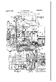
- Fig. 1 is a view, partly in side elevation and partly in vertical section, of the head portion of a machine in which the invention is embodied;
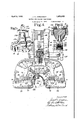
- Fig. 2. is a vertical section ina plane-substantially at right angles to the plane'of section of F ig. ⁇ 1, showing portions of the structure of the machine as positioned for the driving of the upper-fastening tacks;
- Fig. 3 is a sectional view similar to a portion of Fig.l 2, showing the parts as positioned at the end of the tack-driving operation;
- Fig. 4 is a view, partly in plan and partly in section, illustratingmore clearly the construction of the wiper-operating means
- Fig. 5 is a perspective view of a portion of the wiper and tacker mechanism
- Fig. 6 is a plan view, w1th portions of the structure removed, illustrating more fully the relation of the wiper and tacker mechanism to the shoe at the time of the racking operation
- Fig. 7 shows.in disassembled relation the wipers and portions of their supporting means
- Fig. 8 is a section perpendicular to the plane of the Wipers, in a location indicated by the line VIII-VIII of Fig: 7
- Fig. 9 is a'section perpendicular to the plane of the wipers, in a location indicated by the line IX-IX of Fig. 7;
- Fig. 10 is a section on the line X--X lof Fig. 2, illustrating more fully the character of the tack-positioning means; and v Fig. 11 is a View, partly in front elevation andi-ipartly in section, showing details of the shoe-supporting means.
- Machines of this type are designed especially for the shaping of shoe upper materials a (hereinreferred to inclusively as theupper) about the heel end of a last b, and include means for wiping the margin of the upper inwardly over a sole or insole c on the last and means for driving a plurality of fastenings such as tacks to lfasten the margin of the upper in overwiped position.
- the invention is lillustrated by reference tothe lasting of a shoe of the McKaysewed type, but it is to be understood that the machine may be used in the manufacture of shoes of various kinds, and the term sole is therefore frequently used hereinafter in a ⁇ generic sense to designate that part to which the upper is fastened in lasting,
- Machines of the type illustrated comprise a shoe support or jack, hereinafter more particularly referred to, upon which the shoe and last are supported Iand by swinging movement of which the shoe is positioned with its heel end portion within a heel-ernbracing band 12.
- This heel band is supported in the machine and is closed about the heel end of the shoe in the power operation of the machine by mechanism fully shown and described in ,the above-mentioned Lettersv Patent and whichA need not be described herein.
- the machine For wiping the margin of the upper rinwardly over the sole about the heel end of the last, the machine is provided with a pair of wipers 16 and 18 mounted for swinging movements toward and from each other about an axis located, as indicated at (Fig. 7), at the meeting point of the wiping edges of the tWo wipers.
- the wiper 16 is provided with an arm or extension 20 which is curved in an are concentric with the above-mentioned axis
- the wiper 18 is provided with a similarly curved arm or extension 22 in sliding engagement with the extension 20.
- the two arms or extensions 20 andf 22 are thus provided with bearing surfaces concentric with the axis of swinging movement of the wipers and in engagement with each other as indicated at 24,-'and also with bearing surfaces which are parallel to the plane of the ⁇ wipers and are in engagement with each other as indicated at 26.
- the wipers are mounted on a wiper holder comprising a slide 28 and a pair of clamp members 30 and 32 which are secured together and to the slide 28 by means of a screw 34.
- the member 30 is provided with a tongue 36 4which is seated within a groove 38 in the extension 22 of the wiper 18-when the parts are in assembled relation, this tongue and groove also being curved about the axis of swinging mov-ement of the wipers, and there is a similar tongueandroove connection 40, 42 between the mem er 32 and the extension 20 of the wiper 16.
- connection 44,' 46 between the two members-30 and 32 4to assist in positioning these members in proper relation to each other.
- T he wiper-supporting slide 28 is mounted in a guideway in the head of the machine for rectilinear movements lengthwise of the Shoe to advance and retract the wipers, and is provided at its rear end with a cylindrical extension 48 (Figs. 1 and 4) which is mounted in a socket in the head to assist in guiding it.
- Overlapping a ortion of the slide is a cover plate 50 secure to the head of the machine, this cover plate having a slot 52 in which an upstanding portion of the screw 34 is guided in the movements of the'slide 28.
- the slide 28 is operated by means of a path cam l54 formed in a cam wheel 56 which is mounted on a cam shaft 58 and is operated by means fully described in the above-mentioned Let-1f machine slides 64 (Figs. 2 and 4), one for each of the wipers, and each slide 64 has secured thereto by means of a screw 66 a mem ber 68 in which there is formed a slot 70 to receive a roll 72 carried by the adjacent wiper.
- the cover plate 50 overlaps the slides 64 and is provided with' slots 74 in which upstanding portions of the screws 66 are movable.
- the wiper-supporting slide 28 carries a member 76 provided on each of its opposite sides with a series of rack teeth 78 in engagement with a curved rack 80 formed on one end of a lever 82 which is pivotally mounted at 84 on the head of'the machine.
- a curved rack 86 On the opposite end of the lever 82 is a curved rack 86 which engages and operates a pinion 88 in engagement with teeth formed on a rack member 90 secured adjustabl by a screw 91 in af'recess in the slide 64'.
- the connections between the member 76 and the slide 28 are such that by adjusting this member relatively to the slide the wipers may be adjusted about the axis of their swinging movements to position them in proper relation to each other for operating on shoes of different sizes.
- the member 76 is mounted in a recess in the slide 28 with provision for limited movements lengthwise of the slide and is provided with a pair of downwardly extending lugs 92 (Figs. 4) which it within recesses formed in a block 94 also movable lengthwise of the slide ⁇ 28 and provided with a bore having screw threads engaged bythe threads of a shaft 96.
- the shaft 96 is rotatably mounted at its opposite ends in bearing blocks 98 which -are inserted in recesses in the slidel 28, and
- a vbevel-gear 100 engaged by another bevel-gear. 102 provided with. a cylindrical stud 104 mounted in a bearing in one side of the slide 28. It will. thus be seen that by turning the gear 102 the interiorly threaded block 94 may be moved in one direction or the other lengthwise of the slide 28, carrying with it the member 76 uponv which the rack teeth 78 are formed, and that through the connections between these rack teeth and the slides'64 the wipers are adjusted about the axis of their swinging mcvements.
- a shaft 106 having on its inner end a tongue 108 arranged to enter a recess 110 formed inthe stud 104 when the shaft 106 is moved inwardly from the position illustrated in F ig. 4.
- the shaft 106 may thus be moved inwardly against the resistance of a spring 109 which ⁇ acts normally tohold it disconnected from the stud 104 and thus to avoid interference with the operative movement of the slide 28,
- the shaft 106 is in'alinement with the stud 104 and the tongue 108 may be connected to the stud by pushing the shaft inwardly. Then, by use of a hand wheel 110 on the shaft the required adjustment of the wipers may be effected.
- the illustrated machine is provided with means carried by the wipers 16, 18 for driving up er-fastening tacks through openings 112 tig. 7) extending through the wipers in locations near their wiping edges.
- Each of the wipers is provided at its inner edge with an upstanding ange 114 in which there are Nformed in perpendicular relation to the plane of the wipers a series of grooves 116 in alinement with the openings 112.
- tack fingers 124 which are i pressed by springs 126 toward the flange 114 and are so shaped as to co-operate with the grooves 116 of the flange to provide pockets for receiving and positioning upper-fastening tacks t.
- the tacks are fed to the tack pockets through flexible tubes 128 which are connected to the blocks 120 and lead from tack-supplying mechanism 130 of the same character as provided heretofore in machines of the type illustrated.
- each of the blocks 120v are a plurality of tack drivers 132 which are secured at their upper ends to a curved driver block 134 movable in a similarly curved recess provided in the block 120. It will be seen that the driver blocks 134 and the drivers 132 are thus movable in a direction substantially perpendicular i to the plane of the Wipers.
- a stud 136 On the upper end of each of the blocks 134 is mounted a stud 136 which is located in a slot formed in an inverted T-shaped operating member 138 and is provided with a head which overlaps this member.
- yThe member 138 is pivoted at 140 (Fig.
- the tacker blocks120 are not only secured to the wipers by the bolts 118, but are also overlapped b a portion of the wiper-supporting and guiding member -30 (Fig. 1) on the slide 28, and by portions of the slides 64 (Figs. 2 and 4) through which the closing and opening movements of the wipers are effected. Between the overlapping 'portion of each slide 64 and the block -120 there is mounted a plate 164 which is between the slide and the member 68 and is secured in place by the screw 66.
- the means hereinbefore described for positioning the tacks t over the openings 112 in the wlpers is accordingly so constructed that the tacks as they are supported under the drivers are inclined in directions leading inwardly away from the edge of the shoe bottom, as lillustrated in Fig. 2.
- the tack lingers 124 which co-operate with the Wiper flanges 114 to provide pockets for the tacks, have sloping faces centrally grooved
- the spring-controlled fingers 124 whicli are yieldable in response to the movement of the drivers 132, serve by enare thus driven into the shoe materials in directions inclined inwardly away from the edge of the shoe bottom and in various angu lar relations to one another, each tack being inclined in a plane substantially perpendicular to that portion of the edge of the shoe bottom which is nearest thereto.
- the lower end faces of the drivers 132 are so inclined tack-driving operation, theingers are retracted far enough to permit the heads of the tacks to pass.
- the means for supporting the last and shoe for the operations hereinbefore described comprises a jack mounted for swinging movements in directions lengthwise of the. shoe to carry the shoe into and out of lasting position in the same general manner as illustrated in Letters Patent No. 1,558,737, granted on October 27 1925 upon an application of R. F. McFeely, the jack including a member or post 166 (Fig. 11) which carries a heel pin or spindle 168 adapted to projectinto the usual spindle hole p ovided in the heel end of the last. It is desirable that in the heel-seat lasting operation the wipers shall wipe the margin of the upper inwardly with substantially the same pressure at the opposite sides of the heel seat. In diiferent lasts, however.
- the spindle holes are not always bored in uniform angular relation to the bottom faces of the lasts.
- the machine herein shown is accordingly provided with work-supporting means whereby thevdesired pressure relation between the wipers and the opposite sides of the heel seat will be ⁇ secured notwithstanding ysuch variations in the construction of different lasts.
- the upper end of the post 166 is provided with a slot extending laterallv of the shoe, and the portions of the post at the opposite sides of the slot have upper faces, one of which is' shown at 170, providing a guideway curved about an axis indicated bv the point g/ (Fig. 11).
- a l block 172 which carries the spindle 168.
- this block having shoulders curved similarly to the faces 170 and seated thereon.
- the block 172 and the spindle 168 are thus permitted to move laterally7 of the shoe about an axis located. as illustrated, substantially at the heelseat face of the shoe and substantially midwav between the opposite sides of the shoe, so that thetsho'e mav be adiusted to position the opposite sides of the heel seat in substanf tiallv the same relation to the plane of the wipers without any substantial lateral bodilv displacement of the shoe relativelv to the heel band and the wipers.
- the block 172 and the spindle 1.68 are normallv centralized by means of a spring 174 which is mounted in a recess in the lower end of the block and is held under compression between disks 176 sli din-glv movable in the recess in which the spring is mounted. the spring and the disks being held in assembled relation in the block by a lug 178 which isV securedcto the block'in engagement with one of the disks.
- the block 172 is provided with a transverse slot extending across it below the spring 174, and extendin into this slot in en agement with the disks 1 6 are lugs 180 whlch are secured to the post 166.
- the block 172 and its spindle are normally centralized b the spring 174, they may move in either dlrection along the curved guideway 170 against the resistance of the spring.
- the operator may elfect such movement by tipping the last-.rin one direction or the other as he presents the shoe to the machine, or the movement may result from excess of pressure of the wipers at one side or the other of the heel seat, the arrangement thus being such that if the shoe is not presented initially in position to receive substantially the same wiper pressure at the opposite sides of the heel seat, the pressure will be substantially equalized automatically in the operation of the machine.
- a screw 182 shown in section, which is mounted in the post 166 and projects into a slot 184 in the block 172.
- axis y is herein illustrated as located exactly on the heel-seat face of the insole c, as it would preferably be, for example, in operating on a shoe of average size, it will be understood that the position of the axis in .relation to the shoe bottom will vary slightly in the operation of the machine on shoes of dii'erent sizes. Such variation is not enough to result in any material lateral displacement of a shoe of any size within the small range of adjustment necessary for securing equa zation of pressure on the heel seat. Novel features of the illustrated shoe-supporting means are claimed in a divisional application,
- the shoe In the operation of the machine, brieiy summarized, the shoe is positioned in the manner hereinbefore describedv and is clamped about its heel end in the power operation of the machine by the action of the heel band 12.
- the wipers 16 and 18 are then advanced and closed by the cam 54 and the operating connections hereinbefore described to wipe the margin of the heel end portion of the upper inwardly over the sole, the cam in the onstruction herein shown being'so shaped that there are thus imparted to the wipers two full overwiping movements in succession.
- the tacks At the end of the second overwiping movement and while the wipers aremaintained at the inner limit of that movement, the tacks are driven through the openings 112 in the wipers to secure the.
- the two driver blocks 134 are moved downl wardly to cause the drivers to drive the tacks from the tack pockets and into the shoe.
- the tack fingers 124 hold them with their points and heads against the vertical walls of the grooves 116 until they begin to enter the shoe, after which they follow substantially the inclined courses thus determined until they are driven fully in and are clinched on the metal plate d on the last, as illustrated in Fig. 3. It willbe evident that with the tacks thus driven-in predetermined inwardly inclined directions, insurance is afforded that they will be clinched inwardly in directions away from the edge of the shoe bottom. After the tacks have thus been driven the drivers are lifted and the wipers are retracted from over the shoe, the various parts of the machine being returned to their starting positions.
- the numbers of the ⁇ tacks may be varied by the use of means with which machines of the type illustrated areI customarily provided for either permitting or preventing delivery of tacks to one or more of the tack pockets at each side located nearest to the front end of the heel seat.
- tack e which is an assembling tack driven and clinched as usual 1n the assembling of the shoe materials prior to the heel-gat lasting operation, this y tack occupying a position'between the rearmost tacks driven by the mechanisms carried by the wipers.
- edge of the shoe bottom used in defining the relation of the fastenings to the shoe is to-be understood as meaning, with reference to each fastening, that portion of the edge which is nearest to the location of the fastening.
- a machine of the class described having, in combination,'wipers movable to wipe themargin of an upper inwardly over a sole dicular to the plane of the wipers to drive fastenings for securing the margin of the upper in overwiped position, and means for controlling the fastenings in such-manner as to cause them to be driven into the shoe in directions inclined inwardly away from the edge of the shoe bottom by the movement of the drivers.
- a machine of the class described having, in combination, wipers movable to wipe the margin of an upper inwardly over a sole about an end of a shoe, a plurality of drivers movable in directions substantially perpendicular to the plane of the wipers to drive i tacks for securing the margin of the upper in overwiped position, andxmeans for posiabout an end of a shoe, a plurality of driversA movable in directions substantially perpendicular to the plane of the wipers to drive tacks for securing the margin o f the upper in overwiped position, and means for positioning each tack prior to its entry into the shoe with its point and one side of its head substantially tangential to a line 'parallel to the direction of movement of its driver and in lsuch relation to the shoe as to direct the tack on an incline inwardly away from the edge of the shoe bottom as itis driven, each driver having its tack-engaging end face so inclined as to position it in substantially palillel
- a machine of the class described having, in combination, wipers movable to wipe the margin of an upper inwardly over a sole about an end of a shoe, a plurality of drivers movable in directions substantially perpendicular to the plane of the wipe-rs to drive tacks for securing the margin of the upper in overwiped position, means arranged to present for each tack a guide wall substantially parallel to the direction of the movement of its driver and located at that side of the tack which is farthest from the edge of the shoe bottom, and a plurality of springcontrolled tack lingers arranged to press the points and the heads of the tacks against their guide walls in the tack-driving operation to direct the tacks inwardly away from the edge of the shoe bottom as they are driven, the drivers being so formed'as to present tack-engaging end faces substantially parallel to the heads of the inclined tacks.
- 7,'A machine of the class described having, in combination, wipers movable to wipe the margin of an upper inwardly over a sole about an end of a shoe, a plurality of drivers movable in directions substantially perpendicular to the plane of the wipers to drive tacks for securing the margin of the upper in overwiped position, means arranged to present for each tack a guide wall substantially parallel to the direction of the movement of its driver and located ⁇ at that side of the tack which is farthest from the edge of the shoe bottom, and yieldable tackv lingers arranged to co-operate with said guide walls to provide pockets for the tacks, said fingers and guide walls being so formed and arranged as to provide restricted openings leading from the tack lpockets adjacent to the guide walls to receive the lower ends of the tacks and position the tacks initially with their points and heads against said guide walls in inclined relation to the drivers.
- drivers being so formed l'as to present tackabout an end of a shoe, and means for driving a plurality of tacks into the shoe in directions inclined inwardly away from the edge of the shoe bottom for securing the margin of the upper in overwiped position, said .3
- means comprising a plurality of drivers operatively movable in directions substantially perpendicular tothe plane of the wipers and provided with tack-engaging end faces inclined to said plane for driving the tacks at the desired inclinations.
- a machine of the class described having, in combination, wipers movable to wipe the margin of an upper inwardly over a sole about an end of a shoe, aplurality of drivers movable in directions substantially perpendicular to the plane of the wipers to drive fastenings for securing the margin ⁇ of the upper in overwiped position, and means carried by the wipers for positioning the fastenings in such inclined relation tothe paths of movement of the drivers as to cause them to be driven into the shoe in directions inclined inwardly away from the edge of the shoe bottom by the movement of the drivers.
- a machine of the class described having, in combination, wipers movableto wipe' the margin of an upper inwardly over a sole about an end of a shoe and provided with a plurality of openings extending through them, a plurality of drivers mounted to move inwardly with said wipers in fixed relation thereto and movable in directions substantially perpendicular to the plane of the wipers to dr'ge fastenings through said openings for securing the margin of the upper in overwiped position, and means for controlling the fastenings in such manner as to cause them to enter the shoe in directions inclined' inwardly away from the edge of the shoe bottom in response to the movement of the drivers.
- a pair of wipers mounted for swinging movements to wipe the margin of an upper about the heel end of a last inwardly over the bottom of the last, a gang of drivers carried by each of said wipers and movable in a direction substantially perpendicular to the plane of the wipers to drive fastenings for securing the-margin of the upper in overwiped position, and'means for controlling said fasten'ings in such manner as to cause them to entei"Y the shoe in directions inclined inwardly away from the edge of the shoe bottom in response to the movement of the drivers.
- a machine of the class described hav-y ing, in combination, a pair of wipersv mounted for swinging movements to wipe the mar-y plurality of openings extending through it adjacent to said flange, a device secured in xed relation to each wiper and having a plurality of yieldable members constructed and arranged to co-operate with said flange to provide pockets for a plurality of fastening's, and means for driving the fastenings through the openings in the wipers to secure the margin of the upper in overwiped position.
- a machineofthe class described having, in combination, a pair of wipers mounted for swinging movements to wipe the margin of an' upper inwardly over a sole about an end of a shoe, each of said wipers having thereon an upstanding flange and having a plurality of openings extending through it adjacent to said flange, means movable with each wiper for positioning a plurality of tacks with their points and heads against said flange to ineline them relatively to the plane of the wipers in directions leading inwardly away from theedge of the shoe bottom, and means for driving the tacks thus positioned through the openings in the wipers to secure the margin of the upper in overwiped position.
- a machine of the class described having, in' combination, a pair of wipers mount- -plurality of openings extending through it i ed for swinging movements to wipe the margin of an upper inwardly over a sole about an end of a shoe, each of said wipers having a plurality of openings extending through it and havlng thereon an upstanding Hangs provided with grooves in substantially perpendicular relation to the plane of the wiper and in alinement with said openings, yieldable' means carried by each wiper constructed to co-operate lwith said grooves to provide pockets for a plurality of tacks'and to position the tacks with their points and heads against the walls of the grooves to incline them relatively to the plane of the wipers in directions leading inwardly away from the edge of the shoe bottom, and drivers movable in directions substantially perpendicular to the plane of the wipersl to drive the tacks through the openings in the wipers for securing the margin of the upper in
- a machine of the class described having, in combination, meansmovable inwardly over the bottom of a shoe to lay the margin of the upper over the sole, a driver movable in a direction substantially perpendicular to the direction of inward movement of said overlaying means to drive a fastening into the shoe in a direction inclined inwardly away from the edge of the shoe bottom by the movement of the driver.
- a pair of wipers mounted for swinging movements to wipe the margin of an end portion of an upper inwardly over a form, sald wipers having curved arms extending therefrom and arranged for engagement with each other to assist in guiding them in their swinging movements.
- a pair of wipers mounted for swinging movements about. an axis located substantially at the wiping edge thereof to wipe the margin of an end portion of an upper inwardly over a form, said wipers having extensions provided with bearing surfaces curved in arcs concentric with said axis and arranged for engagement with each other to assist in guiding the wipers in their swinging movements.
- a lpair of wipers mounted for swinging" move- Vments about an axis located substantially at Inl the wiping edge thereof to wipe the margin of an end portion of an upper lnwardly over a form, said wipers having extensions provided with bearing surfaces curved in arcs concentric with saidaxis and arranged for enga-gement with each other to assist in guiding the wipers in their swinging movements,
Landscapes
- Footwear And Its Accessory, Manufacturing Method And Apparatuses (AREA)
Description
J. C. JORGENSEN MACHINE FOR SHAPING SHOE UPPERS AApril 5, 1932.
Filed April 16, 1929 5 Sheecs-Shee-'rl .APil 5, 1932- I I J. c. JoRGENsEN 1,852,015
MACHINE FOR SHAPING SHOE'UPPER-S Filed April 16, 1929` 3 Sheets-Sheet 2 Figl, a m 3:11. 0 136 16 "y zo F1g.5.. 36
zo l
0 e ooo f/ 1| l I I i 4 0 30 JZ sa 10 7 April 5, 1932. J, Q JORGENSEN 1,852,015
MACHINE FOR SHAPIG SHOE UPPERS Filed April 16, 1929 5 Sheets-Sheet .'5
Patented Apr. 5,1932
UNITED STATES PA'I'IEN'IJOFFICE JACOB C. JORGENSEN, OF BEVERLY, MASSACHUSETTS, AVSSIGNOR TO UNITED SHOE MA- CHINERY CORPORATION, OF PATERSON, NEW JERSEY, A. CORPORATION OF NEW JERSEY Application mea April 1e,
This invention relates to machines for use in the manufacture of shoes for shaping uppers over lasts or other forms. The invention isherein illustrated as embodied in a machine for lastin the heel ends of shoes, but it is to be un erstood that in its more general aspects it is not limited to heel-endlasting machines.
For shaping the heel ends of shoe uppers there have. been provided heretofore machines having wipers for wiping the margin of the/heel end of an upper inwardly over a she bottom part, such as a sole or insole, mounted on a last or other form, and means for driving a plurality of permanent fastenings, such as tacks, to secure the margin of the upper in overwped position. An object of vthe present invention, in one important' aspect, is-to provide improvements in an organization of that general character, including end-wipin means and fastening means, and more particularly to provide a construction such that the u per will be fastened morej tightly and smoot ly than heretofore and with more satisfactory results in operating on shoes of different sizes. With this general object in view, the machine herein shown is so constructed that the fastenings are driven through openings in the wipers, so that the upper may be fastened without retracting the wipers from their innermost wiping position, and are driven, moreover, in invariably spaced relation yto one another at t each side of the heel seat in operating on shoes of different sizes. For driving the fastenings in this manner each of the'wipersin the con:` struction illustrated. carries with it in its movement over the shoe a gang. of drivers mounted in fixed parallel relation to one another and movable as a unit in a direction substantially vperpendicular to the plane of ythe wipers to drive the fastenings, such an organlzation of wipers and drivers being re-.
garded as the most satisfactory from the point of view of simplicity and compactness of structure and facility of operation of the driving'means. It is, however, very desirable that the upper-securing fastenings be driven in directlons inclined inwardly away from the edge of the shoe bottom, especially MACHINE Fon sHAPING snon nPPERs 1929. Serial No. 855,566.
vinsure that the fastenings as the are driven willhave. no loosening effect on t e upper but willi'rather tend to draw its margm more tightly inward over the shoe bottoni. The y machine herein shown is accordingly further so constructed that while the drivers are movable, as above ex lained, in directions substantially perpen icular to the plane of the wipers, the fastenings are driven in inwardly inclined directions. As yherein illustrated the fastenings utilized are tacks, and for the purpose in' view the tacks are so positioned as to incline them inwardly inthe desired directions relatively to the drivers, the' latter also heilig so formed as to present end faces inclined in substantially parallel 'relatons to the heads of the inclined tacks to assist in maintaining the inclinations of the tacks. The tacks as they are driven are thus all in- .clined inwardly away from the edge of the shoe bottom in various angular relations to one another by the action of the parallel drivers.
While the machine herein shown thus comprises an organization whereby fastenings, inserted at inclinations such as described by the action of drivers movable perpendicularly to the plane of the wipers, are driven through openings in the wipers, it is considered that in some of its novel and useful aspects the invention is not limited to a construction in which the fastenings are driven through .the wipers; and it is further considered that in various aspects the invention is not limited in utility to an organization in which the'fasy tening means is carried by the wipers.
' In addition to features involving the driving of fastenings in inwardly linclined directions, as above set forth, vfeatures of novelty are also to be recognized in other aspects of the illustrated combination of wiping and fastening means; and the invention still further provides improvements in end wiper mechanism, relating particularly to means for-guiding the wipers in their operative movements.
The above and other features of the invention, including various novel details of con-` struction and combinations of arts, will now be more particularly describe by reference to the accompanying drawings and pointed out in the claims.
In the drawings,
Fig. 1 is a view, partly in side elevation and partly in vertical section, of the head portion of a machine in which the invention is embodied;
Fig. 2.is a vertical section ina plane-substantially at right angles to the plane'of section of F ig.` 1, showing portions of the structure of the machine as positioned for the driving of the upper-fastening tacks;
Fig. 3 is a sectional view similar to a portion of Fig.l 2, showing the parts as positioned at the end of the tack-driving operation;
Fig. 4 is a view, partly in plan and partly in section, illustratingmore clearly the construction of the wiper-operating means;
Fig. 5 is a perspective view of a portion of the wiper and tacker mechanism;
Fig. 6 is a plan view, w1th portions of the structure removed, illustrating more fully the relation of the wiper and tacker mechanism to the shoe at the time of the racking operation Fig. 7 shows.in disassembled relation the wipers and portions of their supporting means;
Fig. 8 is a section perpendicular to the plane of the Wipers, in a location indicated by the line VIII-VIII of Fig: 7
Fig. 9 is a'section perpendicular to the plane of the wipers, in a location indicated by the line IX-IX of Fig. 7;
Fig. 10 is a section on the line X--X lof Fig. 2, illustrating more fully the character of the tack-positioning means; and v Fig. 11 is a View, partly in front elevation andi-ipartly in section, showing details of the shoe-supporting means.
The invention is herein illustrated as embodied in a machine of the same general type as that disclosed in United Statesl Letters Patent No. 1,583,044, granted on May 4, 1926,
' upon an application of C. H. Hoyt, and accordingly only such portions of the machine as it is necessary to refer to for an understanding of the invention will be described herein in detail. Machines of this type are designed especially for the shaping of shoe upper materials a (hereinreferred to inclusively as theupper) about the heel end of a last b, and include means for wiping the margin of the upper inwardly over a sole or insole c on the last and means for driving a plurality of fastenings such as tacks to lfasten the margin of the upper in overwiped position. The invention is lillustrated by reference tothe lasting of a shoe of the McKaysewed type, but it is to be understood that the machine may be used in the manufacture of shoes of various kinds, and the term sole is therefore frequently used hereinafter in a `generic sense to designate that part to which the upper is fastened in lasting,
whether it IbeV the insole of certain types 'of shoes or that part which, in shoes of other types, may be the outsole or the only sole withwhich the shoe is provided.
Machines of the type illustrated comprise a shoe support or jack, hereinafter more particularly referred to, upon which the shoe and last are supported Iand by swinging movement of which the shoe is positioned with its heel end portion within a heel-ernbracing band 12. This heel band is supported in the machine and is closed about the heel end of the shoe in the power operation of the machine by mechanism fully shown and described in ,the above-mentioned Lettersv Patent and whichA need not be described herein. `In the course of the i termine the heightwise -position of the shoe relatively to the wiping and fastening mechnism hereinafter described.
For wiping the margin of the upper rinwardly over the sole about the heel end of the last, the machine is provided with a pair of wipers 16 and 18 mounted for swinging movements toward and from each other about an axis located, as indicated at (Fig. 7), at the meeting point of the wiping edges of the tWo wipers. To assist in maintainingthe two wipers in proper relation to each other and in guiding them in their swinging mov'ements, in accordance With one of the objects of this invention, the wiper 16 is provided with an arm or extension 20 which is curved in an are concentric with the above-mentioned axis, and the wiper 18 is provided with a similarly curved arm or extension 22 in sliding engagement with the extension 20. By reference to Figs. 8 and 9 it will be seen that the two arms or extensions 20 andf 22 are thus provided with bearing surfaces concentric with the axis of swinging movement of the wipers and in engagement with each other as indicated at 24,-'and also with bearing surfaces which are parallel to the plane of the` wipers and are in engagement with each other as indicated at 26. The wipers are mounted on a wiper holder comprising a slide 28 and a pair of clamp members 30 and 32 which are secured together and to the slide 28 by means of a screw 34. The member 30 is provided with a tongue 36 4which is seated within a groove 38 in the extension 22 of the wiper 18-when the parts are in assembled relation, this tongue and groove also being curved about the axis of swinging mov-ement of the wipers, and there is a similar tongueandroove connection 40, 42 between the mem er 32 and the extension 20 of the wiper 16. There is also a tongue-and-groove. connection 44,' 46 between the two members-30 and 32 4to assist in positioning these members in proper relation to each other. It will thus be seen that the wipers are securely held in assembled relation by means whereby they are firmly supported and are guided for swinging movements about their common axis.
T he wiper-supporting slide 28 is mounted in a guideway in the head of the machine for rectilinear movements lengthwise of the Shoe to advance and retract the wipers, and is provided at its rear end with a cylindrical extension 48 (Figs. 1 and 4) which is mounted in a socket in the head to assist in guiding it.
Overlapping a ortion of the slide is a cover plate 50 secure to the head of the machine, this cover plate having a slot 52 in which an upstanding portion of the screw 34 is guided in the movements of the'slide 28. The slide 28 is operated by means of a path cam l54 formed in a cam wheel 56 which is mounted on a cam shaft 58 and is operated by means fully described in the above-mentioned Let-1f machine slides 64 (Figs. 2 and 4), one for each of the wipers, and each slide 64 has secured thereto by means of a screw 66 a mem ber 68 in which there is formed a slot 70 to receive a roll 72 carried by the adjacent wiper. The cover plate 50 overlaps the slides 64 and is provided with' slots 74 in which upstanding portions of the screws 66 are movable. For imparting operative movements to the slides 64 the wiper-supporting slide 28 carries a member 76 provided on each of its opposite sides with a series of rack teeth 78 in engagement with a curved rack 80 formed on one end of a lever 82 which is pivotally mounted at 84 on the head of'the machine. On the opposite end of the lever 82 is a curved rack 86 which engages and operates a pinion 88 in engagement with teeth formed on a rack member 90 secured adjustabl by a screw 91 in af'recess in the slide 64'. dt will thus be seen that asthel wiper-supporting slide 28 moves forward to advance the wipers lengthwise of the shoe, the slides 64.v through the connections described are moved inwardly toward the shoe to impart closing movements to the wipers, and that as the slide 28 is retracted, the slides 64 are likewise retracted to vopen the wipers. It will be understood that byvv the elongated slots and the rolls 72 operative connections are maintained between the slides 64 and the wipers in all po-v sitions of the wipers lengthwise of the shoe. The connections between the member 76 and the slide 28 are such that by adjusting this member relatively to the slide the wipers may be adjusted about the axis of their swinging movements to position them in proper relation to each other for operating on shoes of different sizes. For this purpose the member 76 is mounted in a recess in the slide 28 with provision for limited movements lengthwise of the slide and is provided with a pair of downwardly extending lugs 92 (Figs. 4) which it within recesses formed in a block 94 also movable lengthwise of the slide`28 and provided with a bore having screw threads engaged bythe threads of a shaft 96. The shaft 96 is rotatably mounted at its opposite ends in bearing blocks 98 which -are inserted in recesses in the slidel 28, and
fast on the shaft is a vbevel-gear 100 engaged by another bevel-gear. 102 provided with. a cylindrical stud 104 mounted in a bearing in one side of the slide 28. It will. thus be seen that by turning the gear 102 the interiorly threaded block 94 may be moved in one direction or the other lengthwise of the slide 28, carrying with it the member 76 uponv which the rack teeth 78 are formed, and that through the connections between these rack teeth and the slides'64 the wipers are adjusted about the axis of their swinging mcvements. For turning the gear 102 there is mounted in the head of the machine a shaft 106 having on its inner end a tongue 108 arranged to enter a recess 110 formed inthe stud 104 when the shaft 106 is moved inwardly from the position illustrated in F ig. 4. The shaft 106 may thus be moved inwardly against the resistance of a spring 109 which `acts normally tohold it disconnected from the stud 104 and thus to avoid interference with the operative movement of the slide 28, When the parts of the machine are in start ing positions, as illustrated in Fig. 4, the shaft 106 is in'alinement with the stud 104 and the tongue 108 may be connected to the stud by pushing the shaft inwardly. Then, by use of a hand wheel 110 on the shaft the required adjustment of the wipers may be effected.
For securing the margin of the upper'in overwiped position in the manner contem plated by the present invention the illustrated machine is provided with means carried by the wipers 16, 18 for driving up er-fastening tacks through openings 112 tig. 7) extending through the wipers in locations near their wiping edges. Each of the wipers is provided at its inner edge with an upstanding ange 114 in which there are Nformed in perpendicular relation to the plane of the wipers a series of grooves 116 in alinement with the openings 112. Secured in fixed relation to each of the wipers by means of bolts, one of which is shown at 118 in Fig.'5, isfa lac tacker block 120 provided with a plurality of driver passages 122 in line with the grooves 116. Mounted vin recesses in each block 120 are tack fingers 124 which are i pressed by springs 126 toward the flange 114 and are so shaped as to co-operate with the grooves 116 of the flange to provide pockets for receiving and positioning upper-fastening tacks t. The tacks are fed to the tack pockets through flexible tubes 128 which are connected to the blocks 120 and lead from tack-supplying mechanism 130 of the same character as provided heretofore in machines of the type illustrated.
Mounted in the driver passages 1220i each of the blocks 120v are a plurality of tack drivers 132 which are secured at their upper ends toa curved driver block 134 movable in a similarly curved recess provided in the block 120. It will be seen that the driver blocks 134 and the drivers 132 are thus movable in a direction substantially perpendicular i to the plane of the Wipers. On the upper end of each of the blocks 134 is mounted a stud 136 which is located in a slot formed in an inverted T-shaped operating member 138 and is provided with a head which overlaps this member. yThe member 138 is pivoted at 140 (Fig. 1) on a link 142, and the upper end of this link is pivoted at 144 on a driver-operating head 146 guided for vertical movements on a fixed rod 148. vThe head 146 is connected by a link 150 to a lever 152 pivotally supported at its rear end on a link. 154. The lever 152 is operated and controlled by means constructed substantially as shown and described in the Letters Patent hereinbefore mentioned, comprising a cam 156 on the shaft 58 which acts through a plunger 158 to lift the lever and with it the driver-operating head 146,
- and springs 160 (only one of which is shown) which act through rods 162 to impart downward driver-operating movement to the lever when permitted by the cam 156. It will be evident that when the lever 152 is moved upwardly by its cam the member 138 acts through the studs 136 to lift the driver blocks 134 and thereby to retract the drivers 132, and that by reason of the slots in the member 138 and the pivotal connection of the link 142 with this member and with the head 146, the operative connections between the driver blocks 134 and their operating means are maintained at all times without interfering with the movements of the wipers.
It will be seen that the tacker blocks120 are not only secured to the wipers by the bolts 118, but are also overlapped b a portion of the wiper-supporting and guiding member -30 (Fig. 1) on the slide 28, and by portions of the slides 64 (Figs. 2 and 4) through which the closing and opening movements of the wipers are effected. Between the overlapping 'portion of each slide 64 and the block -120 there is mounted a plate 164 which is between the slide and the member 68 and is secured in place by the screw 66.
It will be evident that the arrangement above described, whereby a gang of drivers 132 is carried by each of the wipers andl is movable as a unit in a direction perpendicular to the plane of the wipers, is structurally simple and compact, and that it also permits the drivers to be readily operated by the comparatively simple means illustrated. It is desirable, however, that the tacks be driven in directions inclined inwardly away from the edge of the shoe bottom, in order that as they are driven they will have no loosening effect on the upper but will rather tend to draw it more tightly over the last. This is especially desirable in heel-seat lasting by reason of the fact that the heel seat of a shoe' is usually more or less convex. The means hereinbefore described for positioning the tacks t over the openings 112 in the wlpers is accordingly so constructed that the tacks as they are supported under the drivers are inclined in directions leading inwardly away from the edge of the shoe bottom, as lillustrated in Fig. 2. For the purpose in view the tack lingers 124, which co-operate with the Wiper flanges 114 to provide pockets for the tacks, have sloping faces centrally grooved,
as indicated at 165 (Fig. 3), whereby thepoints of the tacks are deflected or guided into the vertical grooves 116`of the wiper flanges when the tacks are fed to the tack pockets. The fingers 124, moreover,`are so formed that they do not enter the grooves 116, and accordingly these grooves provide restricted openings leading from the tack pockets which receive the lower ends of the Shanks of the tacks. ,The tacks thus become wedgedfin these grooves with their points projecting downwardly below the lingers 124, as illustrated in Fig. 2, and with both their Ypoints and their heads against the vertical Walls of the grooves, so that they are inclined in the manner desired. Furthermore, in the driving operation the spring-controlled fingers 124, whicli are yieldable in response to the movement of the drivers 132, serve by enare thus driven into the shoe materials in directions inclined inwardly away from the edge of the shoe bottom and in various angu lar relations to one another, each tack being inclined in a plane substantially perpendicular to that portion of the edge of the shoe bottom which is nearest thereto. To assist in driving the tacks in this manner the lower end faces of the drivers 132 are so inclined tack-driving operation, theingers are retracted far enough to permit the heads of the tacks to pass.
The means for supporting the last and shoe for the operations hereinbefore described comprises a jack mounted for swinging movements in directions lengthwise of the. shoe to carry the shoe into and out of lasting position in the same general manner as illustrated in Letters Patent No. 1,558,737, granted on October 27 1925 upon an application of R. F. McFeely, the jack including a member or post 166 (Fig. 11) which carries a heel pin or spindle 168 adapted to projectinto the usual spindle hole p ovided in the heel end of the last. It is desirable that in the heel-seat lasting operation the wipers shall wipe the margin of the upper inwardly with substantially the same pressure at the opposite sides of the heel seat. In diiferent lasts, however. the spindle holes are not always bored in uniform angular relation to the bottom faces of the lasts. The machine herein shown is accordingly provided with work-supporting means whereby thevdesired pressure relation between the wipers and the opposite sides of the heel seat will be `secured notwithstanding ysuch variations in the construction of different lasts. For the purpose in view the upper end of the post 166 is provided with a slot extending laterallv of the shoe, and the portions of the post at the opposite sides of the slot have upper faces, one of which is' shown at 170, providing a guideway curved about an axis indicated bv the point g/ (Fig. 11).
Mounted in this slot is the lower portion of a l block 172 which carries the spindle 168. this block having shoulders curved similarly to the faces 170 and seated thereon. The block 172 and the spindle 168 are thus permitted to move laterally7 of the shoe about an axis located. as illustrated, substantially at the heelseat face of the shoe and substantially midwav between the opposite sides of the shoe, so that thetsho'e mav be adiusted to position the opposite sides of the heel seat in substanf tiallv the same relation to the plane of the wipers without any substantial lateral bodilv displacement of the shoe relativelv to the heel band and the wipers. The block 172 and the spindle 1.68 are normallv centralized by means of a spring 174 which is mounted in a recess in the lower end of the block and is held under compression between disks 176 sli din-glv movable in the recess in which the spring is mounted. the spring and the disks being held in assembled relation in the block by a lug 178 which isV securedcto the block'in engagement with one of the disks. The block 172 is provided with a transverse slot extending across it below the spring 174, and extendin into this slot in en agement with the disks 1 6 are lugs 180 whlch are secured to the post 166. It will thus be evident that while the block 172 and its spindle are normally centralized b the spring 174, they may move in either dlrection along the curved guideway 170 against the resistance of the spring. The operator may elfect such movement by tipping the last-.rin one direction or the other as he presents the shoe to the machine, or the movement may result from excess of pressure of the wipers at one side or the other of the heel seat, the arrangement thus being such that if the shoe is not presented initially in position to receive substantially the same wiper pressure at the opposite sides of the heel seat, the pressure will be substantially equalized automatically in the operation of the machine. In. order to limit the extent of movement of the block 172 there is further provided a screw 182, shown in section, which is mounted in the post 166 and projects into a slot 184 in the block 172.
While-the axis y is herein illustrated as located exactly on the heel-seat face of the insole c, as it would preferably be, for example, in operating on a shoe of average size, it will be understood that the position of the axis in .relation to the shoe bottom will vary slightly in the operation of the machine on shoes of dii'erent sizes. Such variation is not enough to result in any material lateral displacement of a shoe of any size within the small range of adjustment necessary for securing equa zation of pressure on the heel seat. Novel features of the illustrated shoe-supporting means are claimed in a divisional application,
Serial No. 549,400 filed on July 8, 1931.
In the operation of the machine, brieiy summarized, the shoe is positioned in the manner hereinbefore describedv and is clamped about its heel end in the power operation of the machine by the action of the heel band 12. The wipers 16 and 18 are then advanced and closed by the cam 54 and the operating connections hereinbefore described to wipe the margin of the heel end portion of the upper inwardly over the sole, the cam in the onstruction herein shown being'so shaped that there are thus imparted to the wipers two full overwiping movements in succession. At the end of the second overwiping movement and while the wipers aremaintained at the inner limit of that movement, the tacks are driven through the openings 112 in the wipers to secure the. margin of the upper in overwi-ped position. It will be understood that prior to the driving operation the tacks are supplied to the tack pockets and are held therein in positions inclined inwardly away from the edge of the shoe bottom, as hereinbefore more ,particularly described. When the cam 156 releases the lever 152 to the action of the `sprmgs 160,
the two driver blocks 134 are moved downl wardly to cause the drivers to drive the tacks from the tack pockets and into the shoe. As the tacks are forced downwardly by the drivers, the tack fingers 124 hold them with their points and heads against the vertical walls of the grooves 116 until they begin to enter the shoe, after which they follow substantially the inclined courses thus determined until they are driven fully in and are clinched on the metal plate d on the last, as illustrated in Fig. 3. It willbe evident that with the tacks thus driven-in predetermined inwardly inclined directions, insurance is afforded that they will be clinched inwardly in directions away from the edge of the shoe bottom. After the tacks have thus been driven the drivers are lifted and the wipers are retracted from over the shoe, the various parts of the machine being returned to their starting positions.
Experience has demonstrated that it is entirely practicable, at all events for heel-seat lasting, to use the same wipers in operating on shoes of widely different sizes including, in fact, the entire range of sizes of adults shoes, the wipers and the tacking means thereon being adjusted for different sizes by the described mechanism controlled by the hand wheel' 110. It will laccordingly be evident that the upper-fastening tacks driven through each wiper are spaced at equal distances fromone anotherin the-different sizes ofshoes, which is a very desirable condition from the shoe-making standpoint. For widely differing sizes the numbers of the `tacks may be varied by the use of means with which machines of the type illustrated areI customarily provided for either permitting or preventing delivery of tacks to one or more of the tack pockets at each side located nearest to the front end of the heel seat.
In Fig. 6 there is shown at the rear end of the heel seat a tack e-which is an assembling tack driven and clinched as usual 1n the assembling of the shoe materials prior to the heel-gat lasting operation, this y tack occupying a position'between the rearmost tacks driven by the mechanisms carried by the wipers. y
In the appended claims the expression edge of the shoe bottom used in defining the relation of the fastenings to the shoe is to-be understood as meaning, with reference to each fastening, that portion of the edge which is nearest to the location of the fastening.
Having described the invention, what I claim as new and desire to secure by Letters Patent of the United States is f- 1. A machine of the class described having, in combination,'wipers movable to wipe themargin of an upper inwardly over a sole dicular to the plane of the wipers to drive fastenings for securing the margin of the upper in overwiped position, and means for controlling the fastenings in such-manner as to cause them to be driven into the shoe in directions inclined inwardly away from the edge of the shoe bottom by the movement of the drivers. Y
2. A machine of the class described having,
in combination, wipers movable to Wipe the.
margin of an upper inwardly over a ,sole about anend of a shoe, a plurality of drivers movable in directions substantially perpendicular to the plane ofthe wipers to drive fastenings for securing the margin ofthe upper in overwiped position, and means for maintaining the fastenings until they begin to enter the shoe in such inclined relation to the paths of movement of the drivers as todirect them inwardly away from the edge of the shoe bottom as they are driven.
3. A machine of the class described having, in combination, wipers movable to wipe the margin of an upper inwardly over a sole about an end of a shoe, a plurality of drivers movable in directions substantially perpendicular to the plane of the wipers to drive i tacks for securing the margin of the upper in overwiped position, andxmeans for posiabout an end of a shoe, a plurality of driversA movable in directions substantially perpendicular to the plane of the wipers to drive tacks for securing the margin o f the upper in overwiped position, and means for positioning each tack prior to its entry into the shoe with its point and one side of its head substantially tangential to a line 'parallel to the direction of movement of its driver and in lsuch relation to the shoe as to direct the tack on an incline inwardly away from the edge of the shoe bottom as itis driven, each driver having its tack-engaging end face so inclined as to position it in substantially palillel relation to the head of the inclined tac v .5. A machine of the class described having,
in combination` wipers movable to wipe the y margin of an upper inwardly over a sole about an end of a shoe, a. plurality of drivers movable in directions substantially perpendicular to the plane of the wipers to drive tacks for securing the margin of the upper v in overwiped position, means arranged to present for each tack a guide wall substantially parallel tothe direction of the inovement of its driver and located at that side of the tack which is farthest from the edge of the shoe bottom, and means for yieldingly pressing the point and the head of each tack against said guide wall to direct the tack inwardly away froln the edge of the shoe bottom as it is driven.
6. A machine of the class described having, in combination, wipers movable to wipe the margin of an upper inwardly over a sole about an end of a shoe, a plurality of drivers movable in directions substantially perpendicular to the plane of the wipe-rs to drive tacks for securing the margin of the upper in overwiped position, means arranged to present for each tack a guide wall substantially parallel to the direction of the movement of its driver and located at that side of the tack which is farthest from the edge of the shoe bottom, and a plurality of springcontrolled tack lingers arranged to press the points and the heads of the tacks against their guide walls in the tack-driving operation to direct the tacks inwardly away from the edge of the shoe bottom as they are driven, the drivers being so formed'as to present tack-engaging end faces substantially parallel to the heads of the inclined tacks.
7,'A machine of the class described having, in combination, wipers movable to wipe the margin of an upper inwardly over a sole about an end of a shoe, a plurality of drivers movable in directions substantially perpendicular to the plane of the wipers to drive tacks for securing the margin of the upper in overwiped position, means arranged to present for each tack a guide wall substantially parallel to the direction of the movement of its driver and located `at that side of the tack which is farthest from the edge of the shoe bottom, and yieldable tackv lingers arranged to co-operate with said guide walls to provide pockets for the tacks, said fingers and guide walls being so formed and arranged as to provide restricted openings leading from the tack lpockets adjacent to the guide walls to receive the lower ends of the tacks and position the tacks initially with their points and heads against said guide walls in inclined relation to the drivers.
8. A machine of the class described having, in combination, wipers movable to wipe the margin of an upper inwardly over a sole about an end of a shoe, a plurality of drivers movable-in directions substantially perpendicular to the plane of the wipers to drive tacks for Securing the margin of the upper' in overwiped position, and means for positioning the tacks in such inclined relation to the paths of movement of the drivers as to direct them inwardly away from the edge 'of the shoe bottom as they are driven, the
drivers being so formed l'as to present tackabout an end of a shoe, and means for driving a plurality of tacks into the shoe in directions inclined inwardly away from the edge of the shoe bottom for securing the margin of the upper in overwiped position, said .3
means comprising a plurality of drivers operatively movable in directions substantially perpendicular tothe plane of the wipers and provided with tack-engaging end faces inclined to said plane for driving the tacks at the desired inclinations.
10. .A machine of the class described having, in combination, wipers movable to wipe the margin of an upper inwardly over a sole about an end of a shoe, aplurality of drivers movable in directions substantially perpendicular to the plane of the wipers to drive fastenings for securing the margin `of the upper in overwiped position, and means carried by the wipers for positioning the fastenings in such inclined relation tothe paths of movement of the drivers as to cause them to be driven into the shoe in directions inclined inwardly away from the edge of the shoe bottom by the movement of the drivers.
11. A machine of theI class described having, in combination, means for working the margin of an upperinwardly over a sole about an end of a shoe, a plurality of drivers all movable in substantially parallel relation to one another for driving fastenings at both sides of the end of the shoe bottom to secure the margin of the upper to kthe sole, and means for controlling the fastenings in such manner as to cause each fastening to enter the shoe in a direction inclined inwardly Daway from the edge of the shoe bottom in a plane substantially perpendicular to said edge in response to the movement of its driver.
12. A machine of the class described having, in combination, means for working the margin of an upper inwardly over a sole about an. end of a. shoe, a plurality of drivers all movable in substantially parallel relation to one another for driving tacks at both sides of the end of the shoe bottom to secure the margin of the upper to the sole, and yieldable means for positioning said 'tacks in such inclined relation to the paths the margin of an upper inwardly over a solev about an end of a shoe and provided with a plurality of openings vextending through them, a plurality of drivers movable in directions substantially perpendicular to the plane of the wipers to drive fastenings through s a1d openings for securing the margin of the up- ;f ,per in overwiped position, and means for positioning the fastenings in such inclined relation to the paths of movement of the drivers as to cause them to be driven into the shoe in directions inclined inwardly away from the edge ofthe shoe bottom by the movement of the drivers. v
14.- A machine of the class described having, in combination, wipers movableto wipe' the margin of an upper inwardly over a sole about an end of a shoe and provided with a plurality of openings extending through them, a plurality of drivers mounted to move inwardly with said wipers in fixed relation thereto and movable in directions substantially perpendicular to the plane of the wipers to dr'ge fastenings through said openings for securing the margin of the upper in overwiped position, and means for controlling the fastenings in such manner as to cause them to enter the shoe in directions inclined' inwardly away from the edge of the shoe bottom in response to the movement of the drivers.
15. A machine of the class described having, in combination, wipersmovable to Wipe the margin of an upper inwardly over a sole about an end of a shoe and provided with a plurality of openings extending through them, a plurality of drivers mounted to move inwardly with said wipers in fixed relation thereto and movable in directions substantially perpendicular to the plane of the wipers to drive fastenings through said openings for securing the margin of the upper in overwiped position, and means for maintaining the fastenings until they begin to enter the shoe in such inclined relation to the paths of movement of the drivers as to direct them inwardly away from the edge of the shoe bottom as they are driven.
16. A machine of the class described having, in combination, wipers movable to wipe l the margin of'an upper inwardly over a sole 'about an end of a shoe and provided with a plurality of openings extending through them, a plurality ofdrivers mounted to move inwardlywith saidwipers in fixed relation thereto and movable in directions substantially perpendicular tothe plane of the wip.- ers to drive tacks through said openings for securing the margin of the upper in overwiped position, and means for positioning the tacks in such inclined relation to the paths of movement of the drivers as to direct them inwardly away from the edge of the shoe bottom as they are driven, the drivers being so l formed as to present tack-engaging end faces substantially parallel tothe heads of thel inclined tacks.
17. A heel-end-lasting machine having, in
combination,a pair of wipers mounted for swinging movements to wipe the margin of an upper about the heel end of a last inwardly over the bottom of the last, a gang of drivers carried by each of said wipers and movable in a direction substantially perpendicular to the plane of the wipers to drive fastenings for securing the-margin of the upper in overwiped position, and'means for controlling said fasten'ings in such manner as to cause them to entei"Y the shoe in directions inclined inwardly away from the edge of the shoe bottom in response to the movement of the drivers.
18. A heel-end-lasting machine having, in comibnation, a pair of wipers mounted for swinging movements to wipe the margin of an upper about the heel end of a last inwardly over the bottom of the last, a gang of drivers carried by each of said wipers and movable in a direction substantially perpendicular to the plane of the wipers to drive tacks'for securing the margin of the upper in overwiped position, and means for positioning said tacks in vsuch inclined relation to the paths of movement of the drivers as to direct them inwardly away from the edge of the shoebottom as they are driven, the drivers being so formed as to present tack-engaging end faces substantially parallel to the heads of the inclined tacks.
19. A heel-end-lasting machine having, in combination, a pair of wipers mounted for swinging movementsto wipe the margin of an upper about the heel end of a last inwardly over the bottom of the last, said wipers having a plurality of openings extending through them, a gang of drivers mounted for movement inwardly with each of said wipers .in fixed relation to one another and movable in a direction substantially perpendicular to the plane of the wipers to drive tacks through said openings for securing the margin ofthe upper` in overwiped position, and means for positioning said tacks Yin such inclined rela-` .adjacentto said flange, means movable with each wiper constructed to co-operate with said flange to providepockets'for a plurality of fastenings, and means for driving the fastenings through the openings in the wipers to secure the margin of theupper in overwiped position.
21. A machine of the class described hav-y ing, in combination, a pair of wipersv mounted for swinging movements to wipe the mar-y plurality of openings extending through it adjacent to said flange, a device secured in xed relation to each wiper and having a plurality of yieldable members constructed and arranged to co-operate with said flange to provide pockets for a plurality of fastening's, and means for driving the fastenings through the openings in the wipers to secure the margin of the upper in overwiped position.
22. A machine of the class described having, in combination, a pair of wipers mounted for swinging movements to wipe the margin of an upper inwardly over a'sole about an end of ashoe, each of said wipers having an upstanding'flange thereon and having a plurality of openings extending through it adjacent to said lange, a device secured in fixed relation to each wiper and having a plurality of yieldable members constructed and arranged to co-operate with said flange to provide pockets for a plurality of fastenings, and a plurality of drivers carried by the wipers for driving the fastenings through said openings to secure the margin of the upper in overwiped position.
23. A machine of the class described having, in combination, a pair of wipers mounted for swinging movements to wipe the margin of an upper inwardly over a sole about an end of a shoe, each of said wipers having a plurality of openings extending through it and having thereon an upstanding flange provided with grooves in alinement with said openings, means movable ywith each wiper constructed to co-operate with said grooves to provide pockets for a plurality of fastenings, and means for driving the fastenings through the openings in the wipers to -secure the margin of the upper in overwiped position.
24. A machineofthe class described having, in combination, a pair of wipers mounted for swinging movements to wipe the margin of an' upper inwardly over a sole about an end of a shoe, each of said wipers having thereon an upstanding flange and having a plurality of openings extending through it adjacent to said flange, means movable with each wiper for positioning a plurality of tacks with their points and heads against said flange to ineline them relatively to the plane of the wipers in directions leading inwardly away from theedge of the shoe bottom, and means for driving the tacks thus positioned through the openings in the wipers to secure the margin of the upper in overwiped position.
25. A machine of the class described hav-y ing, iii-combination, a pair of wipers mountan end of a shoe, each of said wipers having thereon an upstanding flange and having a plurality of openings extending through it adjacent to said flange, means movable with each wiper for positioning a plurality of tacks with their points and heads against said flange to incline them relatively to the plane of the wipers in directions leading inwardly away from the edge of the shoe bottom, and drivers movable in directions substantially perpendicular to the plane of the wipers to drive the tacks thus positioned through the openings in the wipers for securing the margin of the upper in overwiped position.
26. A machine of the class described having, in combination, a pair of wipers mounted for swinging movements to wipe the margin of an upper inwardly over a sole about an end of a shoe, each of said wipers having thereon an upstanding flange and having a adjacent to said flange, means movable with each wiper for positioning a plurality of tacks with their points and heads against said flange to incline them relatively to the plane of the wipers in directions leading inwardly away from the edge of the shoe bottom, and a gang of drivers carried by each wiper and movable in a direction substantially perpendicular to the plane of the ywiper to drive the tacks thus positioned through the openings in the wiper for securing the margin of the upper in overwiped position.
27. A machine of the class described having, in' combination, a pair of wipers mount- -plurality of openings extending through it i ed for swinging movements to wipe the margin of an upper inwardly over a sole about an end of a shoe, each of said wipers having a plurality of openings extending through it and havlng thereon an upstanding Hangs provided with grooves in substantially perpendicular relation to the plane of the wiper and in alinement with said openings, yieldable' means carried by each wiper constructed to co-operate lwith said grooves to provide pockets for a plurality of tacks'and to position the tacks with their points and heads against the walls of the grooves to incline them relatively to the plane of the wipers in directions leading inwardly away from the edge of the shoe bottom, and drivers movable in directions substantially perpendicular to the plane of the wipersl to drive the tacks through the openings in the wipers for securing the margin of the upper in overwiped position.
28. A ing, in combination, a pair of wipers mounted for swinging movements to wipe the mar-,- gin of an upper inwardly over a sole about an end of a shoe, each of said wipers having a plurality of openings extending through it and having thereon an upstanding :dange provided with grooves in substantially perpendicular relation to the plane of the wiper and machine of the class described havin alinement with said openings, a member secured in fixed relation to each of said wipers and provided with driver passages in alinement with said grooves, drivers in said passages, and means co-operating with the grooves of said fiange to position the fastenings in such inclined relation to the paths of movementof the drivers as to cause them toenter the shoe in directions inclined inwardly away from the edge of the shoe botttom in response to the movement of the drivers for securing the margin of the upper in overwiped position.
29. A machine of the class described having, in combination, a pair of wipers mounted for swinging movements to wipe the margin of an upper inwardly over a sole about an end of a shoe, each of said `wipers having .a plurality of openings extending through it and having thereon an upstanding flange provided with grooves in substantially perpendicular relation to the plane of the wiper and in'alinement with said openings, yieldable tack fingers arranged to co-operatewith said grooves to provide pockets for a pluralit of tacks and so formed as to permit the ower ends of the tacks to follow said4 ooves below the fingers when the tacks are 7 ed to the tack pockets to position them with their points and heads against the walls of said grooves in inclined relation to the plane of the wipers, and drivers movable in substantially perpendicular relation to the plane of the wipers to drive the tacks through the openings 1n the wipers for securing the margin of the upper in .overwiped position.
30. A machine of the class described having, in combination, a pair' of wipers mounted for swinging movements to wlpe the margin of an upper inwardly over a sole about an end of a shoe, each of said wipers having a plurality of openings extending through itand having secured in fixed relation thereto a member provided with a plurality of driver passages in alinement with said openings and extending in substantially perpendicular relation to the plane of the wipers, drivers mounted in said driver passages, and means for positioning fastenings in such inclined relation to the paths of movement of the drivers as to cause them to enter the shoe in directions inclined inwardly away from the edge of the shoe bottom in response to the' movementof the drivers for securing the margin of the upper in overwiped position.
31. A machine of the class described having, in combination, meansmovable inwardly over the bottom of a shoe to lay the margin of the upper over the sole, a driver movable in a direction substantially perpendicular to the direction of inward movement of said overlaying means to drive a fastening into the shoe in a direction inclined inwardly away from the edge of the shoe bottom by the movement of the driver.
32. A machine of the class described having,in combination, a wiper movable inwardly over the bottom of a shoe to lay the margin of the upper over the sole, said wiper having an opening extending through it, a driver movable inwardly with said wiper and movable in a direction substantially perpendicular to the plane of the wiper to drive a fastening through said opening for securing the margin of the upper in overwiped position, and means for controlling the fastening in such manner as to cause it to be'driven into the shoe in a direction inclined inwardly away from the edge of the shoe, bottom by the movementof the driver.
33. A machine of the class described having. in combination, means movable inwardly'over the bottoml of a shoe to lay the mar 'n of the upper over the sole, a drlver mova Ie in a direction substantially perpendicularto the direction of inward movement of said overlaying means to drive a tack for securing the margin of the upper to the sole, and means for positioning the tack in such inclined relation to the direction .of movement of the driver as to direct it inwardly away from the edge of the shoe bottom as it is driven, the driver having its tack-engaging end face so inclined as to position it in substantially parallel relation to the head of the inclined tack.
34. In a machine of the class described, a pair of wipersmounted for swinging movements to wipe the margin of an end portion of an upper inwardly over a form, sald wipers having curved arms extending therefrom and arranged for engagement with each other to assist in guiding them in their swinging movements. i
35. In a machine of the class described, a pair of wipers mounted for swinging movements to wipe the margin of an end portion of an upper inwardly over a form, said wipers having curved arms extendin therefrom and arranged for engagement -wit each other to assist in guiding them in their swinging movements, and a wiper holder having curved bearing surfaces arranged for engagement with said arms to assist in guiding the wipers.
36. In a machine of the class described, a pair of wipers mounted for swinging movements about. an axis located substantially at the wiping edge thereof to wipe the margin of an end portion of an upper inwardly over a form, said wipers having extensions provided with bearing surfaces curved in arcs concentric with said axis and arranged for engagement with each other to assist in guiding the wipers in their swinging movements.
37. In a machine of the class described, a lpair of wipers mounted for swinging" move- Vments about an axis located substantially at Inl the wiping edge thereof to wipe the margin of an end portion of an upper lnwardly over a form, said wipers having extensions provided with bearing surfaces curved in arcs concentric with saidaxis and arranged for enga-gement with each other to assist in guiding the wipers in their swinging movements,
and a wiper holder having bearing surfaces also curved about said axis and arranged for engagement with said extensions to assist in i guidlng the wi ers.
l to assist in guiding the wilpe ACOB C. J ORGENSEN.
Priority Applications (2)
| Application Number | Priority Date | Filing Date | Title |
|---|---|---|---|
| US355566A US1852015A (en) | 1929-04-16 | 1929-04-16 | Machine for shaping shoe uppers |
| US549400A US1896121A (en) | 1929-04-16 | 1931-07-08 | Machine for shaping shoe uppers |
Applications Claiming Priority (1)
| Application Number | Priority Date | Filing Date | Title |
|---|---|---|---|
| US355566A US1852015A (en) | 1929-04-16 | 1929-04-16 | Machine for shaping shoe uppers |
Publications (1)
| Publication Number | Publication Date |
|---|---|
| US1852015A true US1852015A (en) | 1932-04-05 |
Family
ID=23397909
Family Applications (1)
| Application Number | Title | Priority Date | Filing Date |
|---|---|---|---|
| US355566A Expired - Lifetime US1852015A (en) | 1929-04-16 | 1929-04-16 | Machine for shaping shoe uppers |
Country Status (1)
| Country | Link |
|---|---|
| US (1) | US1852015A (en) |
Cited By (2)
| Publication number | Priority date | Publication date | Assignee | Title |
|---|---|---|---|---|
| US2740138A (en) * | 1951-11-09 | 1956-04-03 | United Shoe Machinery Corp | Machines for operating on the heel end portions of shoes |
| US2846702A (en) * | 1951-11-09 | 1958-08-12 | United Shoe Machinery Corp | Heel end lasting mechanisms |
-
1929
- 1929-04-16 US US355566A patent/US1852015A/en not_active Expired - Lifetime
Cited By (2)
| Publication number | Priority date | Publication date | Assignee | Title |
|---|---|---|---|---|
| US2740138A (en) * | 1951-11-09 | 1956-04-03 | United Shoe Machinery Corp | Machines for operating on the heel end portions of shoes |
| US2846702A (en) * | 1951-11-09 | 1958-08-12 | United Shoe Machinery Corp | Heel end lasting mechanisms |
Similar Documents
| Publication | Publication Date | Title |
|---|---|---|
| US1852015A (en) | Machine for shaping shoe uppers | |
| US2000912A (en) | Machine for shaping shoe uppers | |
| US2499510A (en) | Shoemaking | |
| US2134148A (en) | Lasting machine | |
| US1821966A (en) | Fastening inserting machine | |
| US1303847A (en) | End-wiper mechanism for lasting-machines | |
| US1500152A (en) | Machine for working uppers over lasts | |
| US2268597A (en) | Shoe machine | |
| US1815295A (en) | Machine for inserting fastenings | |
| US2846702A (en) | Heel end lasting mechanisms | |
| US2073028A (en) | Lasting machine | |
| US1886279A (en) | Lasting machine | |
| US2095245A (en) | Machine for pressing the bottoms of shoes | |
| US2001732A (en) | Machine for shaping shoe uppers | |
| US2117331A (en) | Lasting machine | |
| US2336035A (en) | Shoe-supporting means for shoe machines | |
| US2138099A (en) | Lasting machine | |
| US1627999A (en) | Lasting machine | |
| US2357841A (en) | Lasting machine | |
| US1979269A (en) | Lasting machine | |
| US1996879A (en) | Fastening-inserting machine | |
| US1949539A (en) | Lasting machine | |
| US1335779A (en) | Lasting-machine | |
| US2297697A (en) | Lasting machine | |
| US2167738A (en) | Lasting machine |