US1852013A - Spray nozzle - Google Patents
Spray nozzle Download PDFInfo
- Publication number
- US1852013A US1852013A US482216A US48221630A US1852013A US 1852013 A US1852013 A US 1852013A US 482216 A US482216 A US 482216A US 48221630 A US48221630 A US 48221630A US 1852013 A US1852013 A US 1852013A
- Authority
- US
- United States
- Prior art keywords
- spray
- nozzle
- outlet
- washing
- spray nozzle
- Prior art date
- Legal status (The legal status is an assumption and is not a legal conclusion. Google has not performed a legal analysis and makes no representation as to the accuracy of the status listed.)
- Expired - Lifetime
Links
Images
Classifications
-
- B—PERFORMING OPERATIONS; TRANSPORTING
- B04—CENTRIFUGAL APPARATUS OR MACHINES FOR CARRYING-OUT PHYSICAL OR CHEMICAL PROCESSES
- B04B—CENTRIFUGES
- B04B15/00—Other accessories for centrifuges
- B04B15/12—Other accessories for centrifuges for drying or washing the separated solid particles
Definitions
- My present invention relates to a spray nozzle and more particularly to an improved nozzle for controlling the spray of water in sugar washing centrifugals.
- the principal object of my invention is to provide a new and novel type .of spray nozzle for sugar washing centrifugals having features and advantages not possessed by nozzles heretofore provided for this purpose.
- a further object of my invention is to provide in a nozzle of the so called fan spray type a means whereby the direction of the spray can be changed in the plane of the spray without disturbing the position of the nozzle proper.
- Another object of my invention is to provide in a spray nozzle of the type described a means for preventing a drip from the nozzle when the pressure of the liquid being sprayed is insufiicient to form a proper spray.
- Another object of my invention is to provide in a spray nozzle of the fan or sheet spray type a means whereby the distribution 5 of the liquid in the sheet of spray may be varied in a simple manner.
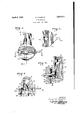
- Figure 1 is a front elevation of my improved nozzle showing the spray outlet on the left side
- Figure 2 is a vertical sectional view taken along line IIII of Figure 1,
- Figure 3 is a horizontal sectional view taken along line III-III of Figure 1, and
- Figure 4 shows a preferred type of spray aperture forming spacer and director.
- the crystallized sugar as taken from the evaporating pans contains" a certain amount of uncrystallized juice which must be separated from the crystals.
- This operation is carried out by placing the sugar in a basket type of perforated receptacle that is rotated at a high speed about a vertical axis and in which the sugar, as it is disposed around the wall of the basket by centrifugal force, is subjected to a high velocity jet or spray of washing water.
- the wash water In order to provide this uniform distribution of the wash water it is customary to project the wash water in the form of a sheet or fan likerspray which distributes the water uniformly between the top and bottom of the washing basket.
- the spray nozzle is generally disposed near the center of the basket and is located so as to direct the sheet of wash water radially outward in a vertical plane.
- the spray outlet In nozzles of the type now used the spray outlet is fixed and as a result any vertical adjustment of the spray in the basket must be accomplished by raising or lowering the nozzle as a whole together with the wash water supply pipe.
- 10 designates the main or body portion of my improved nozzle.
- the body portion 10 is provided with a vertically disposed annular surface 11 and is cored out to provide a conduit 12 for the washing liquid or fluid.
- the upper end of the body portion 10 is internally threaded as at 13 to receive a fluid supply pipe (not this end to form a seat for a ball check valve 15.
- the ball valve 15 in this embodiment is shown as held in engagement with the seat 14. by a helical spring 16.
- the spring 16 is preferably of such size and strength that it will hold the ball 15. in its valve closing position at all times when the fluid pressure is not sufficient to produce a proper spray. If it is desired to provide for an adjustment of the pressure exerted by the spring 16 this can be done by providing an adjustable. seat at the lower end of the spring.
- a member 17 Cooperating With the annals ai are upon the body member 10, I show a member 17 as having an annular surface 18 which is complementary to. the. annular. surface 11 and disposed between these two. surfaces 11 and 18, I provide a spacing or; spray. outlet defining element. 19.
- This spacing element 19 is in theform of; a disk-like memberand has a cut away portion designatedby the numeral 2Q which. defines the'length of a: spray outlet i
- the member. 17 is held upon the nozzle body. 10 by a bolt. 22 and the: spacing. disk 19. is. held in clamped engagement between the annular surfaces 11 and 18-.
- a central opening 23 isprovided in the spacing disk 19 through which'thebolt 22:1nay1 pass.
- the disk 19 may be turned: about the bolttoch-ange the position of the spray outlet 21. between the surfaces11and18.
- cutaway portion inthediskll is cutsufiic-iently deep to permitan" accumulation of r the washing fluidin thecavity 26.
- a spray LlOZZlQDfli'allS character described having a body portion through which. the liquid-to.besp-rayed may pass said'body portion. havinga fiat surface. at its outlet end,
- a spray-nozzleof t he character described having a; body portion. through. which. the
- liquidgto be sprayed may pass, said'body por-.
- tion having an annular-surface at its. outlet end; means havingapartially. flexibleannular surface secured inclamping engagement withsaidfirst annular-surface, and afspacing element disposed: between said surfaces having a cut away part adapted tovbe disposed adjacent the flexible. portion ofrsaid nieans for defining the length and swidth-ofa spray outlet and means for flexing said 'first means lit-d adjacent the spray OlltlhlilO provideanopem.
- a spray nozzle for sugar washing centrifugals and the like, the combination of a pair of oppositely disposed and spaced surfaces between which liquid may pass to normally form a sheet like spray of rectangular cross section, and means for deflecting one of said surfaces at a central point to control the distribution of the liquid and produce a sheet like spray having greater thickness at its edges where it leaves the nozzle than in the center.
- a spray nozzle for sugar washing centrifugals and the like, the combination of a fluid supply conduit a pair of oppositely disposed surfaces forming an outlet for said conduit, a relatively thin spacing means disposed and held in clamped engagement between said surfaces and having a part out away for forming a normally rectangular spray outlet, and means for deflecting one of said surfaces adjacent the spray outlet along a line extending parallel with the long axis of the outlet to control the distribution of the liquid in the spray substantially as described.
- a spray nozzle for sugar washing centrifugals and the like comprising, a body portion adapted to connect with a source of fluid, an end closure member for said body portion secured in clamped engagement therewith by a single axially extending screw, a spacing member disposed between said end closure member and said body portion and rotatably mounted upon said axially extending screw, and means carried by said member whereby it may be moved to change the direction of the spray.
Landscapes
- Nozzles (AREA)
Description
l at e nt ed- Apr. 5, 1932 UNITED STATES GIUSEPPE IACOIBITTI, OF CROCKET'I, CALIFORNIA SPRAY NOZZLE Application filed September 16, 1930. Serial No. 482,216.
My present invention relates to a spray nozzle and more particularly to an improved nozzle for controlling the spray of water in sugar washing centrifugals.
The principal object of my invention is to provide a new and novel type .of spray nozzle for sugar washing centrifugals having features and advantages not possessed by nozzles heretofore provided for this purpose.
A further object of my invention is to provide in a nozzle of the so called fan spray type a means whereby the direction of the spray can be changed in the plane of the spray without disturbing the position of the nozzle proper.
Another object of my invention is to provide in a spray nozzle of the type described a means for preventing a drip from the nozzle when the pressure of the liquid being sprayed is insufiicient to form a proper spray.
Another object of my invention is to provide in a spray nozzle of the fan or sheet spray type a means whereby the distribution 5 of the liquid in the sheet of spray may be varied in a simple manner.
Other objects and advantages of my invention will be in part pointed out and in part evident from the following description taken in connection with the accompanying drawings wherein I have shown, by way of illustration and not of limitation, a preferred form of my invention.
In the drawings wherein like numerals re- 5 fer to like parts throughout the several views:
Figure 1 is a front elevation of my improved nozzle showing the spray outlet on the left side,
Figure 2 is a vertical sectional view taken along line IIII of Figure 1,
Figure 3 is a horizontal sectional view taken along line III-III of Figure 1, and
Figure 4 shows a preferred type of spray aperture forming spacer and director.
In the washing of sugar crystals at the refinery the crystallized sugar as taken from the evaporating pans contains" a certain amount of uncrystallized juice which must be separated from the crystals. This operationis carried out by placing the sugar in a basket type of perforated receptacle that is rotated at a high speed about a vertical axis and in which the sugar, as it is disposed around the wall of the basket by centrifugal force, is subjected to a high velocity jet or spray of washing water. 7
For a proper washing of the sugar crystals in this manner it is necessary that the washing operation'be timed so that the crystals will not be subjected to more water than is required for the elimination of the impurities. It is also necessary that the spray or V jet from the nozzle be so directed that the layer of crystals disposed upon the walls of 6 the basket will be subjected to a uniform amount of 'wash water over the entire surfaceduring the washing operation.
In order to provide this uniform distribution of the wash water it is customary to project the wash water in the form of a sheet or fan likerspray which distributes the water uniformly between the top and bottom of the washing basket. The spray nozzle is generally disposed near the center of the basket and is located so as to direct the sheet of wash water radially outward in a vertical plane. In nozzles of the type now used the spray outlet is fixed and as a result any vertical adjustment of the spray in the basket must be accomplished by raising or lowering the nozzle as a whole together with the wash water supply pipe. Itis important that the spray outlet be properly located with respect to the walls of the centrifugal basket and it is therefore a further object of my invention to provide a means for adjusting the direction of the spray in a simple manner without changing the location of the nozzle or disturbing the supply connections.
For a better understanding of my invention reference should be had to the accompanying drawings'wherein 10 designates the main or body portion of my improved nozzle. The body portion 10 is provided with a vertically disposed annular surface 11 and is cored out to provide a conduit 12 for the washing liquid or fluid. The upper end of the body portion 10 is internally threaded as at 13 to receive a fluid supply pipe (not this end to form a seat for a ball check valve 15. The ball valve 15 in this embodiment is shown as held in engagement with the seat 14. by a helical spring 16. The spring 16 is preferably of such size and strength that it will hold the ball 15. in its valve closing position at all times when the fluid pressure is not sufficient to produce a proper spray. If it is desired to provide for an adjustment of the pressure exerted by the spring 16 this can be done by providing an adjustable. seat at the lower end of the spring.
Cooperating With the annals ai are upon the body member 10, I show a member 17 as having an annular surface 18 which is complementary to. the. annular. surface 11 and disposed between these two. surfaces 11 and 18, I provide a spacing or; spray. outlet defining element. 19. This spacing element 19 is in theform of; a disk-like memberand has a cut away portion designatedby the numeral 2Q which. defines the'length of a: spray outlet i The member. 17 is held upon the nozzle body. 10 by a bolt. 22 and the: spacing. disk 19. is. held in clamped engagement between the annular surfaces 11 and 18-. A central opening 23 isprovided in the spacing disk 19 through which'thebolt 22:1nay1 pass.
With the above construction. it will-.beseen thatwhen the bolt 22is loosened slightlythe disk 19 may be turned: about the bolttoch-ange the position of the spray outlet 21. between the surfaces11and18. The disk 19 .isvshown as provided witha projecting. portioniorhandle'2t to facilitate a: movement thereof when changing the direction of the spray.
By referring to Figuresfl and: 3 of:- the drawings itwillbe seen that in formingcthe r annularisurfaces 11 andl18'upon themem- I bers l0and 17 there are also f-ormeds in these members, cavities 25 and: 26- respectively. The cavity 25- is connected with the conduit 12 by a plurality- 0f; passageways 27 and: the
cutaway portion inthediskll) is cutsufiic-iently deep to permitan" accumulation of r the washing fluidin thecavity 26. By forming'these-cavities -and 26 with substantially the same depth as shown, l -equalize thepres- -:sure on each side-of the sprayopening 21.
*sprayoutlet soasto substantially. equalize the pressure throughout the areaof'thespray.
Byireferfing to Figure. 3 it will be seen that I accomplish the above by. milling outatangentially' extendingslot- 28 in thernember Y 17 immediately in. back of the annular surface 18 and threading a' screw 29 in the remaining portion of the member 17. XVith this construction there will be formed a projecting lip 30 which can be easily deflected and as a result the annular surface 18 at this point may be also deflected inwardly at the spray outlet. In thisv connection it should be noted that the member 17 also rotatable about the bolt 22 and as a result the point of deflection in the annular surface 18 can be moved with the spray outlet or with respect to the WVhile I have, for the sake of clearness and in orderto disclose. my invention so that the same can be readily understood, described and illustrated specific devices and arrangements, I desire. to have it understood: that this. in.- vention is. not limited; to the. specific means disclosed but may be embodied; in. other-ways that will suggest themselves, in. view oh this broad disclosure, to persons. skilled in. the art. It is believed: that this invention is broadly new and; it is. desired to claim. it as such so. that all such. changes as ccmewithin the scope or" the appended claims are to. be considered as part of this. invention.
Having thus described: my invention what I claim. and: desireto secureby Letters Batent is:
1. A spray LlOZZlQDfli'allS character described having a body portion through which. the liquid-to.besp-rayed may pass said'body portion. havinga fiat surface. at its outlet end,
ill)
means secured. in; clamping engagement: with said surface, a spacing. element; disposed between said surface. and; said last means having a part cut. away fordeiining thelength and width of a. spray outlet and means for deflecting said" first means. adjacent the cut away-portion of saidspacing element to diminish the width. off the spray outlet. intermediate itsends,
2. A spray-nozzleof t he character described having a; body portion. through. which. the
liquidgto be sprayed may pass, said'body por-.
tion having an annular-surface at its. outlet end; means havingapartially. flexibleannular surface secured inclamping engagement withsaidfirst annular-surface, and afspacing element disposed: between said surfaces having a cut away part adapted tovbe disposed adjacent the flexible. portion ofrsaid nieans for defining the length and swidth-ofa spray outlet and means for flexing said 'first means lit-d adjacent the spray OlltlhlilO provideanopem.
ing having a greater. widthat itsends. than in thecenter.
3. In a. spray nozzle of. thecharacterydescribed, the combination of a. body member adaptedtto connect with a source of fluidun.
aipartjcnt away to define aspraym tIet, and.
means carried by said disk whereby it may be moved to change the direction of the spray.
4. In a spray nozzle for sugar washing centrifugals and the like, the combination of a pair of oppositely disposed and spaced surfaces between which liquid may pass to normally form a sheet like spray of rectangular cross section, and means for deflecting one of said surfaces at a central point to control the distribution of the liquid and produce a sheet like spray having greater thickness at its edges where it leaves the nozzle than in the center.
5. In a spray nozzle for sugar washing centrifugals and the like, the combination of a fluid supply conduit a pair of oppositely disposed surfaces forming an outlet for said conduit, a relatively thin spacing means disposed and held in clamped engagement between said surfaces and having a part out away for forming a normally rectangular spray outlet, and means for deflecting one of said surfaces adjacent the spray outlet along a line extending parallel with the long axis of the outlet to control the distribution of the liquid in the spray substantially as described.
6. A spray nozzle for sugar washing centrifugals and the like comprising, a body portion adapted to connect with a source of fluid, an end closure member for said body portion secured in clamped engagement therewith by a single axially extending screw, a spacing member disposed between said end closure member and said body portion and rotatably mounted upon said axially extending screw, and means carried by said member whereby it may be moved to change the direction of the spray.
GIUSEPPE IACOBITTI.
Priority Applications (1)
| Application Number | Priority Date | Filing Date | Title |
|---|---|---|---|
| US482216A US1852013A (en) | 1930-09-16 | 1930-09-16 | Spray nozzle |
Applications Claiming Priority (1)
| Application Number | Priority Date | Filing Date | Title |
|---|---|---|---|
| US482216A US1852013A (en) | 1930-09-16 | 1930-09-16 | Spray nozzle |
Publications (1)
| Publication Number | Publication Date |
|---|---|
| US1852013A true US1852013A (en) | 1932-04-05 |
Family
ID=23915183
Family Applications (1)
| Application Number | Title | Priority Date | Filing Date |
|---|---|---|---|
| US482216A Expired - Lifetime US1852013A (en) | 1930-09-16 | 1930-09-16 | Spray nozzle |
Country Status (1)
| Country | Link |
|---|---|
| US (1) | US1852013A (en) |
-
1930
- 1930-09-16 US US482216A patent/US1852013A/en not_active Expired - Lifetime
Similar Documents
| Publication | Publication Date | Title |
|---|---|---|
| US11036243B2 (en) | Vapor splitter and method for adjusting vapor split ratio | |
| US3515348A (en) | Mist-producing device | |
| US3112263A (en) | Device in a screen filter fitted with a sloping screen | |
| US1852013A (en) | Spray nozzle | |
| US2832643A (en) | Flow regulator | |
| US1522982A (en) | Automatic means for controlling the flow of liquid into a tank | |
| US1936413A (en) | Spray nozzle | |
| KR890002245B1 (en) | Branch gate of granular fluid raw material | |
| US2559894A (en) | Shower head | |
| EP0046277A1 (en) | Apparatus for gravity separation of liquid mixtures | |
| US1271939A (en) | Sprinkler-nozzle. | |
| US86158A (en) | Improvement in nozzle-filters | |
| EP0308693B1 (en) | Manual shower for a continuous and pulsating water jet | |
| US883337A (en) | Drainage-valve. | |
| US1119176A (en) | Centrifugal separator. | |
| US1376916A (en) | Bubbler for drinking-fountains | |
| US2106871A (en) | Poultry fountain | |
| DE1816003B2 (en) | Dishwashing machine air expansion chamber - has a lid with an integral air escape tube | |
| KR101990459B1 (en) | Liquid splitter | |
| US837902A (en) | Filter strainer-nozzle. | |
| US1399294A (en) | Condenser | |
| US1261439A (en) | Filter. | |
| US1040875A (en) | Cooling-tower. | |
| US2290237A (en) | Discharge for separators | |
| US1128178A (en) | Convertible spray and jet nozzle. |