US1852003A - Drag line extension boom - Google Patents
Drag line extension boom Download PDFInfo
- Publication number
- US1852003A US1852003A US198373A US19837327A US1852003A US 1852003 A US1852003 A US 1852003A US 198373 A US198373 A US 198373A US 19837327 A US19837327 A US 19837327A US 1852003 A US1852003 A US 1852003A
- Authority
- US
- United States
- Prior art keywords
- boom
- arm
- extension
- yoke
- line extension
- Prior art date
- Legal status (The legal status is an assumption and is not a legal conclusion. Google has not performed a legal analysis and makes no representation as to the accuracy of the status listed.)
- Expired - Lifetime
Links
- 238000010276 construction Methods 0.000 description 7
- 239000007787 solid Substances 0.000 description 1
Images
Classifications
-
- E—FIXED CONSTRUCTIONS
- E21—EARTH OR ROCK DRILLING; MINING
- E21B—EARTH OR ROCK DRILLING; OBTAINING OIL, GAS, WATER, SOLUBLE OR MELTABLE MATERIALS OR A SLURRY OF MINERALS FROM WELLS
- E21B15/00—Supports for the drilling machine, e.g. derricks or masts
Definitions
- My invention relates to an extension boom for use in connection with hoisting devices to e employed in connection with tractors,
- Another object is to provide a support for the end of the boom to make the same more stable in the handling of heavy loads.
- the invention resides particularly in the mechanical construction of the parts and their relations to each other. These features of construction will be set out with greater particularity in the specification which follows.
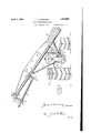
- i is a rear elevation of the tractor with my invention mounted thereon, certain parts being broken away for greater clearness.
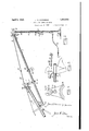
- Fig. 2 is a side elevation of the forward end of the main boom and the extension arm, illustrating the construction of the invention
- Figs. 3 and 4 are side and front elevations respectively of the upper portion of the truss rod attaching bracket constructed 'particularly for use with my improvement.
- Like numerals of reference are employed to designate like parts in all the views.
- the boom 1 is preferably made of tubular construction and will ordinarily be constructed of any pipe or suitable length adapted to be supported upon a tractor, indic'ated generally at A.
- boom are brace rods 5 and 6.
- the boom is also supported by a pair of rods 7 on the opposite side of the tractor frame and eX- tending diagonally upward for-attachment 1 to brackets 9 upon the boom;
- the boom is reinforced by means ofj-a truss rod 10 connected to the opposite ends of the boom and passing over supporting posts ll, 11 at points sp'aced at each side vof the central point of the boom.
- a forward end of the boom has a cap 14 thereon on which is formed a downwardly curved arm 15, to which is nected a yoke 16.
- the said yoke is Securedl to the arm by means of a transverse bolt 17 extending through the upper end of the yoke and the forward end of said arm.
- Said yoke has a sleeve or supporting bearing 18 towards its lower end to receive the extension arm 19.
- the transverse bolt 20 through said yoke allows the sameito be'tightened upon the extension arm so as to hold the same rigidly.
- the extension arm 19 is preferably of tubular construction, although manifestly itv may be made solid, if desired. vThe lower-or inner end thereof is supported within a stirrup 21 clamped to said arm by'meansof the transthe stirrup is pivoted upon a bolt 23 to the lower end of a clamping ring 24 fitting adjustably upon the forward end of the boom '11 I' i 4At the forward end of the extension arm 19 is a cap 25 which has formed thereon a downwardly curved arm 26 having an opening 27 therein to receive an eye-bolt' 28-secured to the collar 29, at the upper end of a supporting post 30.
- a truss rod 32 On the upper side of the cap 25 is an upwardly extending lug 31 having an opening therein to receive a truss rod 32.
- Said truss rod has a nut 33 thereon screwed upon the said rod and adapted to tighten the tension upon the rod 4in an obvious manner.
- the truss rod 32 has adjacent its lower end a lug or flangev 34, secured rigidly to the rod and adapted to engage within the upper forked end 35 of a bracket 36 projecting upwardly from the cap 14 upon the boom 1.
- the said bracket 36 has an opening 37 therein below the forked upper end to receive the forward end of the truss rod 10, previously described.
- the said bracket thereby furnishes attachment for the truss rods upon both boom and extension arm.
- VThe truss rod 32 upon the arm has a plurality of spaced lugs 34' to engage within the forked end of bracket 36, thus allowing the extension understood that when the arm is to be shortened from the position shown in Fig. 2, the adjustable ring 24 securing the inner end of V the arm to the boom 1 will be moved inward- V-on to the proper length so Ltudinally,
- the supporting leg 30 is adjustable longithe upper end thereof being telescopically received within a sleeve 33 projecting upwardly from the base member 39.
- the post 30 has a plurality of openings 39 therethrough to receive a pin 40, so as to vary the height of the post in an obvious manner.
- the pin 40' is preferably secured by means of the 'chain 41 to the body of the post so that it may not become lost.
- a sheave or pulley 42 adjustable along the arm by means of a clamping ring 43 so as to receive a drag line or cable by means of which the load is to be handled.
- the forward arm 26 upon the extension arm may have an opening 44 therein toflwhich a pulley or other supporting member may be secured, if desired.
- the manner in' whichlthe boom extension is employed will be obvious to those skilled in the art, and need not be further considered.
- the lower end of the post 30 may have a lineor cable 45 thereon for attachment to some stationary member to' which the post may be anchored during the hoisting operation.
- V i V i
- clamping ring on one end of said arm adjustable along said boom between its ends, and a yoke provided on the end of said bracket and supporting said arm intermediate the ends thereof.
- a portable support a boom thereon extending laterally from said support, a bracket at the forward end of said boom, a truss rod described,
- tension arm a yoke pivoted on the rforward end of said bracket and engaging said arm, means connecting the rear end of said arm and said boom, a truss rod connected with the forward end of said arm, and lugs on said rod adjustably engaging said forked end of said bracket for the purpose described.
- a drag line extension boom for tractors comprising a main boom, a pivoted yoke on the forward end of said boom, an extension arm supported intermediate its ends by said yoke, an adjustable connection between the end of said arm and said mainboom, and additional means serving to hold said arm in various adjusted positions relative to said boom.
- An extension boom for tractors com'- prising a main boom, a yoke pivotally supported at the forward end of said boom, an extension arm supported intermediate its ends in said yoke and slidable relative thereto, an adjustable connectionbetween the innerl end Vof said'arm and said main boom and an adjustable support for the outer end of said arm.
Landscapes
- Engineering & Computer Science (AREA)
- Life Sciences & Earth Sciences (AREA)
- Geology (AREA)
- Mining & Mineral Resources (AREA)
- Mechanical Engineering (AREA)
- Physics & Mathematics (AREA)
- Environmental & Geological Engineering (AREA)
- Fluid Mechanics (AREA)
- General Life Sciences & Earth Sciences (AREA)
- Geochemistry & Mineralogy (AREA)
- Jib Cranes (AREA)
Description
April 5, 1932- V J. MMMMMMMM Gs 1,852,003 I April5, 1932. J..D. cuMMlNGs DRAG LINE ExTENsIoN BooM 2 Sheets-Sheet Filed June 13. 192.7
Patented Apr. 5, 1932 i JAMES I). cUMMINe's,
OF HOUSTON, TEXAS DRAG- LINE EXTENSION BOOIVI' p Application filed June 13,
My invention relates to an extension boom for use in connection with hoisting devices to e employed in connection with tractors,
It is an object of the invention to provide an extension arm to be used upon a boom employed upon tractors or similar movable supports whereby loads may be lifted in connection particularly with oilfield development. It is desired to provide means whereby pipe and similar loads may be hoisted and moved by mechanical means operative in the field.
It is another object to provide means for adjustable support of an extension arm whereby it may be adjustable as to length.
Another object is to provide a support for the end of the boom to make the same more stable in the handling of heavy loads.
The invention resides particularly in the mechanical construction of the parts and their relations to each other. These features of construction will be set out with greater particularity in the specification which follows.
Referring to the drawings herewith, Fig. 1
i is a rear elevation of the tractor with my invention mounted thereon, certain parts being broken away for greater clearness. Fig. 2 is a side elevation of the forward end of the main boom and the extension arm, illustrating the construction of the invention, Figs. 3 and 4 are side and front elevations respectively of the upper portion of the truss rod attaching bracket constructed 'particularly for use with my improvement. Like numerals of reference are employed to designate like parts in all the views.
The mounting and general construction of the main boom upon which my extension is employed is not a part of the present inven- '3 tion, and the construction thereof is hence referred to herein only in general terms.
, The boom 1 is preferably made of tubular construction and will ordinarily be constructed of any pipe or suitable length adapted to be supported upon a tractor, indic'ated generally at A. There are supporting legs 2 and 3 connected with the lower end of the boom, these supporting legs being mounted upon the side of the tractor frame, as shown 59 at 4. On opposite sides of the body of the 'verse bolt 22. The upper end'of 1927. Serial No. 198373.
boom are brace rods 5 and 6. The boom is also supported by a pair of rods 7 on the opposite side of the tractor frame and eX- tending diagonally upward for-attachment 1 to brackets 9 upon the boom; The boom is reinforced by means ofj-a truss rod 10 connected to the opposite ends of the boom and passing over supporting posts ll, 11 at points sp'aced at each side vof the central point of the boom. Upon .the lower end of the boom and on the side of the tractor opposite the load which is to be raised, I provide a plate 12 upon whichv a series of weights 13 of suitable dimensions maybe placed to provide sufficient weight to balance the load which is to be handled at the forward end .of the boom.
A forward end of the boom has a cap 14 thereon on which is formed a downwardly curved arm 15, to which is nected a yoke 16. The said yoke is Securedl to the arm by means of a transverse bolt 17 extending through the upper end of the yoke and the forward end of said arm. Said yoke has a sleeve or supporting bearing 18 towards its lower end to receive the extension arm 19. The transverse bolt 20 through said yoke allows the sameito be'tightened upon the extension arm so as to hold the same rigidly.
The extension arm 19 is preferably of tubular construction, although manifestly itv may be made solid, if desired. vThe lower-or inner end thereof is supported within a stirrup 21 clamped to said arm by'meansof the transthe stirrup is pivoted upon a bolt 23 to the lower end of a clamping ring 24 fitting adjustably upon the forward end of the boom '11 I' i 4At the forward end of the extension arm 19 is a cap 25 which has formed thereon a downwardly curved arm 26 having an opening 27 therein to receive an eye-bolt' 28-secured to the collar 29, at the upper end of a supporting post 30. On the upper side of the cap 25 is an upwardly extending lug 31 having an opening therein to receive a truss rod 32. Said truss rod has a nut 33 thereon screwed upon the said rod and adapted to tighten the tension upon the rod 4in an obvious manner. i'
pivotally con'- .the
arm to be adjusted as to length. It will be The truss rod 32 has adjacent its lower end a lug or flangev 34, secured rigidly to the rod and adapted to engage within the upper forked end 35 of a bracket 36 projecting upwardly from the cap 14 upon the boom 1. The said bracket 36 has an opening 37 therein below the forked upper end to receive the forward end of the truss rod 10, previously described. The said bracket thereby furnishes attachment for the truss rods upon both boom and extension arm. VThe truss rod 32 upon the arm has a plurality of spaced lugs 34' to engage within the forked end of bracket 36, thus allowing the extension understood that when the arm is to be shortened from the position shown in Fig. 2, the adjustable ring 24 securing the inner end of V the arm to the boom 1 will be moved inward- V-on to the proper length so Ltudinally,
ly along the said boom to be attached between the two truss supports 11 and adjusted therethat one of the the forked end lufl's 34' will env'age within b b 2D :of the bracket 36. i The parts may then be adjusted rigidly in position and the tension upon the truss rod 32 may be increased by means of the nut 33 to iirmiy support the extension arm.
The supporting leg 30 is adjustable longithe upper end thereof being telescopically received within a sleeve 33 projecting upwardly from the base member 39. The post 30 has a plurality of openings 39 therethrough to receive a pin 40, so as to vary the height of the post in an obvious manner. The pin 40'is preferably secured by means of the 'chain 41 to the body of the post so that it may not become lost. i
I contemplate placing upon the extension arm 19 a sheave or pulley 42 adjustable along the arm by means of a clamping ring 43 so as to receive a drag line or cable by means of which the load is to be handled. The forward arm 26 upon the extension arm may have an opening 44 therein toflwhich a pulley or other supporting member may be secured, if desired.
The manner in' whichlthe boom extension is employed will be obvious to those skilled in the art, and need not be further considered. The lower end of the post 30 may have a lineor cable 45 thereon for attachment to some stationary member to' which the post may be anchored during the hoisting operation. V i
Having thus described my invention, what I claim as new and desire to protect by Letters Patent is: i
1. In a device of the character described,
clamping ring on one end of said arm adjustable along said boom between its ends, and a yoke provided on the end of said bracket and supporting said arm intermediate the ends thereof.
2. In a device of the character a portable support, a boom thereon extending laterally from said support, a bracket at the forward end of said boom, a truss rod described,
tension arm, a yoke pivoted on the rforward end of said bracket and engaging said arm, means connecting the rear end of said arm and said boom, a truss rod connected with the forward end of said arm, and lugs on said rod adjustably engaging said forked end of said bracket for the purpose described.
4. A drag line extension boom for tractors comprising a main boom, a pivoted yoke on the forward end of said boom, an extension arm supported intermediate its ends by said yoke, an adjustable connection between the end of said arm and said mainboom, and additional means serving to hold said arm in various adjusted positions relative to said boom.
5. An extension boom for tractors com'- prising a main boom, a yoke pivotally supported at the forward end of said boom, an extension arm supported intermediate its ends in said yoke and slidable relative thereto, an adjustable connectionbetween the innerl end Vof said'arm and said main boom and an adjustable support for the outer end of said arm.
ln testimony whereof I hereunto affix my signature this 9th day of June, A. D.'1927.v
i JAMES D. CUMMINGS.,
a portable support, an angularly extending
Priority Applications (1)
| Application Number | Priority Date | Filing Date | Title |
|---|---|---|---|
| US198373A US1852003A (en) | 1927-06-13 | 1927-06-13 | Drag line extension boom |
Applications Claiming Priority (1)
| Application Number | Priority Date | Filing Date | Title |
|---|---|---|---|
| US198373A US1852003A (en) | 1927-06-13 | 1927-06-13 | Drag line extension boom |
Publications (1)
| Publication Number | Publication Date |
|---|---|
| US1852003A true US1852003A (en) | 1932-04-05 |
Family
ID=22733125
Family Applications (1)
| Application Number | Title | Priority Date | Filing Date |
|---|---|---|---|
| US198373A Expired - Lifetime US1852003A (en) | 1927-06-13 | 1927-06-13 | Drag line extension boom |
Country Status (1)
| Country | Link |
|---|---|
| US (1) | US1852003A (en) |
-
1927
- 1927-06-13 US US198373A patent/US1852003A/en not_active Expired - Lifetime
Similar Documents
| Publication | Publication Date | Title |
|---|---|---|
| US2715014A (en) | Vehicle derrick | |
| US3470699A (en) | Safety device for trenches and the like | |
| US2881003A (en) | Device for raising and lowering basketball bankboards | |
| US3163304A (en) | Scoop and loader attachment for tractors | |
| FR3078739B1 (en) | DRILLING MACHINE COMPRISING A CONNECTION DEVICE FOR A VERTICALITY MEASURING DEVICE | |
| US1852003A (en) | Drag line extension boom | |
| US2718719A (en) | Auxiliary blade attachment for bulldozers | |
| US2252514A (en) | Hoist | |
| US2609940A (en) | Crane boom suspension | |
| US2688411A (en) | Collapsible gantry | |
| US2275195A (en) | Gin pole | |
| US2378915A (en) | Suspension for crane booms | |
| US2645523A (en) | Support structure for boom type crop sprayers | |
| US3176854A (en) | Boom suspension system | |
| US2243306A (en) | Power control for earth working devices | |
| US2838182A (en) | Hydraulically operated truck derricks | |
| US1765295A (en) | Tractor boom crane | |
| US2437754A (en) | Jetty | |
| US2621803A (en) | Mobile crane | |
| US979173A (en) | Derrick bull-wheel. | |
| US1949750A (en) | Derrick structure and method for raising a derrick mast | |
| US1649837A (en) | Elevating and supporting bracket | |
| US891796A (en) | Steel derrick and excavating-machine. | |
| US1879848A (en) | Portable transformer and hoist | |
| US1096337A (en) | Derrick for pulling stumps. |