US1851990A - Pressing machine - Google Patents
Pressing machine Download PDFInfo
- Publication number
- US1851990A US1851990A US363769A US36376929A US1851990A US 1851990 A US1851990 A US 1851990A US 363769 A US363769 A US 363769A US 36376929 A US36376929 A US 36376929A US 1851990 A US1851990 A US 1851990A
- Authority
- US
- United States
- Prior art keywords
- valve
- rod
- operating means
- outlet
- parts
- Prior art date
- Legal status (The legal status is an assumption and is not a legal conclusion. Google has not performed a legal analysis and makes no representation as to the accuracy of the status listed.)
- Expired - Lifetime
Links
- 239000012530 fluid Substances 0.000 description 17
- 230000000694 effects Effects 0.000 description 14
- 230000000994 depressogenic effect Effects 0.000 description 5
- 230000006835 compression Effects 0.000 description 4
- 238000007906 compression Methods 0.000 description 4
- 238000010276 construction Methods 0.000 description 3
- 238000000926 separation method Methods 0.000 description 3
- 208000027418 Wounds and injury Diseases 0.000 description 2
- 230000006378 damage Effects 0.000 description 2
- 208000014674 injury Diseases 0.000 description 2
- 230000008878 coupling Effects 0.000 description 1
- 238000010168 coupling process Methods 0.000 description 1
- 238000005859 coupling reaction Methods 0.000 description 1
- 230000003028 elevating effect Effects 0.000 description 1
- 239000004744 fabric Substances 0.000 description 1
- NJPPVKZQTLUDBO-UHFFFAOYSA-N novaluron Chemical compound C1=C(Cl)C(OC(F)(F)C(OC(F)(F)F)F)=CC=C1NC(=O)NC(=O)C1=C(F)C=CC=C1F NJPPVKZQTLUDBO-UHFFFAOYSA-N 0.000 description 1
- 230000010355 oscillation Effects 0.000 description 1
- XXPDBLUZJRXNNZ-UHFFFAOYSA-N promethazine hydrochloride Chemical compound Cl.C1=CC=C2N(CC(C)N(C)C)C3=CC=CC=C3SC2=C1 XXPDBLUZJRXNNZ-UHFFFAOYSA-N 0.000 description 1
- 230000035939 shock Effects 0.000 description 1
Images

Classifications
-
- D—TEXTILES; PAPER
- D06—TREATMENT OF TEXTILES OR THE LIKE; LAUNDERING; FLEXIBLE MATERIALS NOT OTHERWISE PROVIDED FOR
- D06F—LAUNDERING, DRYING, IRONING, PRESSING OR FOLDING TEXTILE ARTICLES
- D06F71/00—Apparatus for hot-pressing clothes, linen or other textile articles, i.e. wherein there is substantially no relative movement between pressing element and article while pressure is being applied to the article; Similar machines for cold-pressing clothes, linen or other textile articles
- D06F71/04—Apparatus for hot-pressing clothes, linen or other textile articles, i.e. wherein there is substantially no relative movement between pressing element and article while pressure is being applied to the article; Similar machines for cold-pressing clothes, linen or other textile articles power-actuated
- D06F71/06—Apparatus for hot-pressing clothes, linen or other textile articles, i.e. wherein there is substantially no relative movement between pressing element and article while pressure is being applied to the article; Similar machines for cold-pressing clothes, linen or other textile articles power-actuated fluid-actuated
- D06F71/062—Apparatus for hot-pressing clothes, linen or other textile articles, i.e. wherein there is substantially no relative movement between pressing element and article while pressure is being applied to the article; Similar machines for cold-pressing clothes, linen or other textile articles power-actuated fluid-actuated with an upper movable pressing member and a lower fixed pressing member
- D06F71/065—Apparatus for hot-pressing clothes, linen or other textile articles, i.e. wherein there is substantially no relative movement between pressing element and article while pressure is being applied to the article; Similar machines for cold-pressing clothes, linen or other textile articles power-actuated fluid-actuated with an upper movable pressing member and a lower fixed pressing member the upper movable member rotating about a fixed axis
- D06F71/067—Fluid-control mechanisms for controlling the ironing pressure or the movement of the pressure member
Definitions
- This invention relates to improvements in machines for pressing fabrics, such as wearing apparel, and has particular relation to improvements in those parts of such machines which control the closing thereof for the pressing operation and the openingthereof.
- Such a machine is closed by bringing about pressingengagement of the two pressing members of the machine and is openedby bringing about disengagement or separation of said members, suflicient separation being preferably produced to provlde convenient access to the lower pressing member for ar-' mally closing outlet valve, said outlet valve.
- a further object of the present invention is the provision of such a pressing machine having improved control mechanism as above specified, with the outlet valve operating means in two parts normally in inoperative relation, and put into operative relation by a means operated by opening-actuation of the inlet valve operating means.
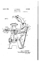
- FIG. 1 is an elevation of the right side of a pressing machine embodying the present inven- PATENT orrlca MAoHInE 1929. Serial No.'863,769.
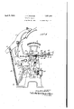
- Fig. 2 is an elevation of the left side of said machine, with parts thereof in section on the line 22, Fig. 3, and parts thereof broken away to show interior construction
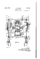
- Fig. 3 is a detail sectional view taken generally onthe line 3-3, Figs. 1 and 2, the cylinder and the valve connections being shown as they are for the sake of clarity
- Fig. 4 is a detail view showing the front part of the operating means for the outlet valve
- Fig. 5 is a. similar view showing the front part of the operating means for the inlet valve
- Fig. 6 is a detail view on the line 6-6, Figs. land 2, of the valve maintaining means
- FIG. 7 is a detail view of the front part of the operating means for the outlet valve, said view being taken on the line 77, Fig. 3;
- Fig. 8 is a longitudinal sectional view of, the exhaustmuflier, the view beingtaken on the line 8-8, F i 2; and
- Fig. 9 1s a detail view of said muffler looking toward the outlet end thereof, with parts broken away to show interior construction.
- the pressing machine illustrated in the drawings includes a suitable frame 1 ona pedestal 2 of which is mounted a lower pressing member 3. Said frame is also provided with a'rearwardly and upwardly ex-- tendingarm ion the upper end of which is pivoted at 5 a head lever 6 carrying at its forward end an upper. pressing'member 7. Connected by the pin 14 to the rear end portion of said head lever are the upper ends of two springs 8 having'their lower ends connected at 9 to the machine frame, said springs tending to move said head lever,
- the means for moving the upper pressing member into and out of pressing-engagement with the lower pressing member includes a toggle comprising an upper member and a lower member 11, the upper end of said lower toggle member being connected to the lower end of the upper toggle member by a-pin 12.
- the upper end of the upper toggle member is connected by means ofa swivel block 13 and the pin'l l to the rear end portion of the head lever 6 while the lower end of the lower toggle member 11 is connected at 9 to the machine frame.
- a piston rod 21 Connected by the pin to the lower toggle member 11, just below the knuckle pin 12 thereof, is the rear end of a piston rod 21 having on its front end a piston 22 movable within a horizontally disposed cylinder 23 mounted for oscillation on the pins in the machine frame 1.
- the purpose of connecting the piston rod 21 to the toggle 10, 11 below the knuckle 12 thereof is to'increase the amount of separation of the two pressing members when the press is open, with a. shorter throw of the piston.
- Either steam or air is suitable formoving the piston 22 in the cylinder 23 to eil ect closing of the press.
- the means for supplying such a fluid to said cylinder includes a pipe 30, Fig. 3, which, if air is the fluid used, may have its inlet end connected to an air compressor (not shown).
- the outlet or discharge end of pipe is connected to the supply side of the casing 31 of an inlet valve 32.
- the flow of fluid through said valve is controlled by a. valve member 33 normally held closed against its seat by a spring 34.
- Connected to the discharge side of said inlet valve casing is one end of a flexible tube 37 having its other end connected to the forward end of the cylinder 23.
- the inlet valve 32 is opened and an outlet or exhaust valve hereinafter described is closed. Steam or air from supply pipe 30 is now free to flow through the inlet valve to the cylinder 23 and the piston 22 in said cylinder is moved rearwardl under the pressure of said steam or air. uch rearward movement of the piston straightens the toggle formed by members 10, and 11 and causes the head lever 6 to move v about its pivot in a counter clockwise direction, Fig. 1, thereby bringing the upper pressmg member 7 downwardly into engagement with the lower stationary pressing member 3, with sufiicient pressure to properly press the work on said lower pressing member.
- a flexible tube 48 has one of its ends connected to the tube 37 near the delivery end thereof and its other end connected to the supply sideof the casing 49 of Learned fluid through this outlet or exhaust .valve is controlled by a valve member 52 normally tending to move to closed position against its seat under the influence of spring 53. Upon the opening of the outlet or exhaust valve, the
- the present control mechanism requires for its operation to effect closing of press the use of both of the operators hands.
- the use oi one of her hands is needed for the operation of the inlet valve and the use other other hand is needed for the operation of the outlet or exhaust valve.
- the use of both hands is required until the pressing members have been brought into engagement or substantially so, after which the liability of injury to her hands is over and she is then free for other duties or for other things, such freedom being due to the provision of the valve maintaining means hereinafter described.
- the inlet valve 32 is arranged on the right side of the machine for operation by the right hand of the operator and the outlet or exhaust valve 45 is arranged on the left side of the machine for operation by the operator's left hand.
- the operating means for the inlet valve includes a hand lever pivoted upon a pin 61 mounted. in a bracket 63 carried by a bracket 64 secured to the right side of the mach-inc frame and supporting the rightside of a work supporting table 65. Said hand lever is provided rearwardly of its pivot 61 with a downwardly extending arm 67 connected to a clevis 68 mounted on the forward end of a rod 69.
- the operating means for the outlet or exhaust valve is in two parts normally out of operative relation.
- the front one includes a hand lever 80 pivoted upon a pin'81 mounted in a bracket 82 carried bya bracket 83 secured to the left side of the machine frame and supporting the left side of the work table 65.
- Said hand lever is provided rearwardly ofits pivot 81 with a downwardly extending arm 85 connected to a clevis 86;
- the other part of said operating means, the rear part includes a rod 87 having its front end portion slidably mounted in the-clevis 86 and provided on its front end with a head 88.
- the middle portion of saidrod extends through a part of the table bracket 83 and the rear end of said rod is secured to a bracket 90 on which is adjustably mounted an operating 'member 91. Said member engages the rear end of a' valve stem 92 having its front end extending I into the outlet valve casing 49 for engagement with the outlet valve member 52.
- lever 80 effects rearward movementof clevis 86,'rod 87, bracket 90, the bracket operating member 91 and the valve stem 92, the 'rearward movement of said valve stem permit ting the outlet valvemember 52 to move rearmall closin valves. to y g wardly to closed position against its seat by its spring 53.
- the inlet valve 32 and the outlet or exhaust valve are nor- When the ress is open, the inlet valve remains close by its I own s ring 34 but separate means must be provi ed' for overcoming the closing effect of the outlet valve spring 53 in order to hold said valve open when the press'is open.
- Said means 'com rises a spring 95 surrounding the rod 8 of the outlet valve operatingmeans and having its rear end engaging that art 'of the table bracket 83 through whic the rod 87 slides.
- the front end of spring 95 engages a collar 96 pinned or otherwise rigidly connected to rod 87. Since the spring 95 is considerably stronger than the outlet valve spring 53, the rod' 87 of the outlet valve operating means is normally maintained in its forward position, with the result that the'valve stem 92is also maintained in its forward position. and the outlet valve member 521is held open by the engagement of said stemwith said valve member.
- the means for maintaining the inlet valve open and permitting the outlet or exhaust valve to remain closed for the pressing operation includes a transversely extending rod 100, preferably of non-circular form, such as square, and having its ends journalled in brackets 101 carried by the table brackets 64 and 83.
- Rigidly secured on the right endportion of rod 100 is a lever 102 having a bifurcated portion 103 straddling the rear end portion of a rod 104 provided on its rear end with a fixed collar or head 105.
- An intermediateportion of said rod 104 extends through a part of the table bracket 64 and the forward end of said rod is connected .bracket 83 and the forward end of said rod is connected to the bracket 90 of the outlet valve operating means.
- a coiled spring 120 Arranged in sleeve 116 between the rod head 115 and the lower end of said sleeve is a coiled spring 120.
- Rods 104 and 109 are thereby held in their rear positions by levers 102 and 107 and the inlet let valve will open under the in valve is therefore maintained open and the outlet valve is maintained closed, the outlet valve being maintained closed because spring 95 is not now effective to pull rod 87 forwardly, and the outlet valve member 52 remains closed under the action of its spring 53.
- Levers 102 and 107 of the maintaining means do not engage the headed rear ends of rods 104 and 109, however, until the pressing members have been brought into” engagement, or substantially so. Therefore, if the operator holds the outlet valve closed but releases the inlet valve hand lever before engagement of the pressing members has been brought about (and hence before the valve maintaining means becomes efiective),
- the inlet valve Will close under the action of its spring 34 and the press will not be closed. If the inlet valve is kept open, but the operator releases the outlet or exhaust valve handle 80. before engagement of the pressing members has been brought about (and hence before the maintaining means becomes effective to resist the spring 95 ofthe outlet valve operating means) the outfluence of spring 95 and the press will not be closed, for the fluid; sup lied to the cylinder 23 will i readily escape t erefrom through the open outlet valve.
- the operating means p for the outlet valve is in two parts normally out of operative relation. When such is the relation of these parts, operation of one part has no effect upon the other.
- the hand lever 80 may be depressed but no movement of rod 87 will be brought about because the clevis 86 simply slides on said rod.
- a spring 125 is arranged on the forward end of rod 87, with the forward end of said spring engaging the clevis 86 and the rear end of said spring engaging a pin or other abutment 126v fast on rod 87. Therefore, when the two parts of the outlet valve operating means are out 1 rod 87;
- the clevis 86 simply slides rearwardly on rod 87 and compresses spring 125 with no appreciable rearward movement of When the hand lever is released, the spring 125 moves the clevis 86 forwardly and elevates the operating partof hand lever 80, as will be readily understood.
- the means for putting the two parts of the outlet valve operating means into operative relation includes two transversely extending rods 130 and 131 having their inner or adjacent ends connected by a coupling 132
- the outer or right end of rod 131 is journalled in the clevis 68 of the inlet valve operating means and the outer or left end of rod 130 is journalled in the clevis 88 of the outlet valve operating means.
- East on the right end of rod 131 is the rear end portion of a lever 134 having its forward end provided with an adjusting screw 135 lying below for operation by the hand lever 60 of the inlet valve operating means.
- l ast on the left end of rod 130 is the forward end of a lever 137 having its rear end 138 arranged below the rod 87 vof the outlet valve operating means just in advance of the collar 96 on said rod.
- the operator simply raises or elevates the left hand lever 80 of the outlet valve operating means, which first effects forward movement of the clevis 86 into engagement with the head 88 on the front end' of rod 87 and then effects forward move-v ment of both said clevis and said rod.
- the spring 120 of the maintaining means In order to move rod 87 forward, the spring 120 of the maintaining means must be still further compressed, but such further compression of said spring does not make it noticeably more diflicult for the operator to raise or elevate hand lever 80.
- Such further com pression of the spring 120 of the maintaining operating means and such forward movement of said valve stem effects an opening of the outlet valve 52, said valve moving against the compression of its spring 53.
- the opening of the exhaust valve 52 efiects,'of course, an exhausting of the fluid within the cylinder 23. said fluid flowing from said cylinder through tube 48, the now opened outlet valve 52, pipe 55 and the hereinafter described.
- the inlet valve operating means and the outlet valve operating means are provided'with push buttons by means of whichthey may be operated by the press operator.
- the inlet valve hand lever 60 has adjustably mounted therein the lower end of a stem 145 having its upper end lying within a sleeve 146 mounted upon the top portion of the bracket 63. Slidably mountedin the upper end portion of this sleeve for operative engagement with the of 80 pounds per square inch or more, there is considerable noise made by the exhaust of the air.
- a suitable mufiler is connected to the discharge end of the exhaust pipe 55 leadin from the outlet or exhaust valve.
- the mu er here shown includes a cylindrical body member 160 to the end cap 161 of which the exhaust pipe 55 is connected.
- the other end cap 162 of thev muffler is provided with a plurality of apertures 163 and arranged within the muffler is a coil of wire mesh 165, which effectively breaks up the forceof the air being exhausted, as will be readily understood.
- a suitable snubber 170 is provided for the head lever 6.
- This snubber is connected to the rear end portion of the head lever 6 by having the rear end of the snubber lever 171 connected to the lower end of a lever 172 hav-v ing its upper end connected to the rear end portion of the head lever, such as to the pin 14 thereof.
- the snubber acts only in one direction so that there will be no resistance. in the .snubber when the head lever 6 is being moved in a clockwise direction, Fig. 2, to effect closing of the press; However, when the head lever 6 is moved in a counter-clockwise direction, Fig. 2, to effect. opening of the press, the snubber will retard such counter-clockwise movement of the head lever and the press will be opened without shock or jar.
- a pair of bumpers are mounted in the rear end of the cylinder 23 for engagement by the piston 22.
- Each of these bumpers includes a bolt 180 having its rear end adjustably mounted in an opening in the rear end wall 181 of the cylinder.
- Said cylinder end wall 181 is provided. with a cylindrical cavity 182 in which the front end portion of bolt 180 lies and arranged in saidcavity, surrounding the bolt, is a spring 183.
- the front end of said spring engages a head 185 on the front end of the bolt and the rear end of said spring engages the cylinder rear end wall 181.
- Mechanism for controlling the flow of fluid to and from a cylinder including two valves, operating means for one of said valves comprising two arts normally out of operative relation, and means controlled by operation of the other valve for putting said parts into operative relation, whereby said parts are capable of valve operation.
- Mechanism for controlling the flow of fluid to and from a cylinder including an inlet valve and an outlet valve, operating means for said outlet valve comprising two parts normally out of operative relation, and means controlled b operation of the inlet valve for d parts into operative relation, whereby said parts are capable of effecting operation of said outlet valve.
- Mechanism for controlling the flow ort fluid to and from a cylinder including an inlet valve and an outlet valve, operating means for said outlet valve comprising two parts normally out of operative relation, and means controlled by openingoperation of the inlet valve for putting said parts into operative relation, whereby said parts are capable of efi'ecting elosing'operation of said outlet valve.
- Mechanism for controlling the flow of fluid to and from a cylinder including two valves, operatingmeans for one of said valves comprisingtwo parts, one of which is an operator operable part, said partsbeing normally out of operative relation, whereby actuat-ion of said operator operable part will not actuate the other part and thecondition of said one valve will not therefore be changed, and means controlled by operation of the other Valve for putting the two parts of the operating means of said one valve into operative relation, whereby actuation of the operator operable part of said operating means will effect actuation of the other part thereof and the condition of said one valve Will thereby be changed.
- Mechanism for controlling the flow of fluid relative to a fluid-receiving cylinder including a valve, operating means for said valve comprising two parts, one of which is an operator operable part having an operated position and an unoperated position, said parts being normally out of operative relation, whereby actuation of said operator operable part will not actuate the other part and the condition of said valve will not therefore be changed, means-for putting the/two parts of said valve operating means into opera-- tive relation, whereby actuation of the operator operable part of said operating means will tor operable part to unoperated position when it is operated and the two parts are out of operative relation.
- Mechanism for controlling the flow of fluid relative to a fluid-receiving cylinder including a valve, operating means for said valve. comprising two parts, one of which is an operatoroperable part having an operated position and an unoperated position and the other of said parts is a valve operating part, said parts being normally out of operative relation, whereby actuation of said operator operable part will not actuate the valve operating part and the condition of said valve will not therefore be changed, means for putting the two parts of said valve operating means into operative relation, whereby actuation of the operator operable part of said operating means will efi'ect actuation of the valve operating part thereof and the condition of said valve will thereby be changed,
- Mechanism for controlling the flow of fluid relative to a fluid-receiving cylinder including a valve, operating means, for said valve comprising two parts normally out of operative relation, one of said parts being an operator operable part having a movable member and the other of said parts being a whereby operation of said operator operable part causes the movable member of said part to effect movement of the element of the valve operating part, with consequent operation of said valve.
- Mechanism for controlling the flow of v fluid. relative to a fluid-receiving cylinder including a valve, operating means for said valve comprising two parts normally out of operative relation, one of said parts being an operator operable part having a movable member and the other of said parts being a valve operating pat-t having an element along .which said movable member slides when said a operator operable part is operated and said parts are out of operative relation, whereby operation of said operator operable part will not actuate the valve operating part and the condition of said valve will not therefore be changed, and means for putting the two parts of said valve operating means into operative relation, whereby operation of the operator operable part of said operating means eil'ects actuation of the valve operating part, with consequent operation of said valve, said putting means including a swinging member movable with the movable member of said operator operable part and an abutment fast on the element of said valve operating part, said swinging member being adapted for engament with said abutment when said
- Mechanism for controlling the flow of fiuid t0 and from a cylinder including two valves, operating means for one of said valves comprising two parts normally out of operative relation, one of said partsbeing an operator operable part having a movable member and the other of said parts being a valve operating part having an element along which said movable member'slides when said operator operable part is operated and said parts are out of operative relation, whereby operation of said operator operable part will not actuate the valve operating part and the condition of said valve will not therefore be changed, means for putting the two parts of said valve operating means into operative relation, whereby operation of the operator operable part of the operating means effects actuation of the valve operating part, with consequent operation of said valve, said putting means includin a swinging member movable with the mova le member of said operator operable.
- said swinging member being adapted for engagement with said abutment when said member is in a certain position of its swing, and means operated by operation of said other valve for putting said swinging member in said certain posi' tion, whereby it engages said abutment.
- mechanism for effecting engagement of said pressing members to thereby bring about closing of the press said mechanism including an inlet valve and an outlet valve, valve operating means for opening said inlet valve, valve operating means for closing said outlet valve, and maintaining means for causing the inlet valve to remain open and the outlet valve to remain closed, said maintaining means including a rearwardly extending rod connected to each valve operating means and provided onits rear end with a head, a transverse shaft on which are fast two levers for engaging the heads of said rearwardly exsignature.
Landscapes
- Engineering & Computer Science (AREA)
- Textile Engineering (AREA)
- Threshing Machine Elements (AREA)
- Shaping Metal By Deep-Drawing, Or The Like (AREA)
- Treatment Of Fiber Materials (AREA)
- Mechanically-Actuated Valves (AREA)
Description
April 5, 1932. J. P. QNGISER 135L9 0 PRESSING MACHINE IBY A TTORNEYJ in detail hereinafter.
Patented Apr. 5', 1932 UNITED STATES JOHN P. SINGISEIR, OF CHICAGO, ILLINOIS, MACHINERY QOMPANY,
PRESSING Application filed May 17,
This invention relates to improvements in machines for pressing fabrics, such as wearing apparel, and has particular relation to improvements in those parts of such machines which control the closing thereof for the pressing operation and the openingthereof. Such a machine is closed by bringing about pressingengagement of the two pressing members of the machine and is openedby bringing about disengagement or separation of said members, suflicient separation being preferably produced to provlde convenient access to the lower pressing member for ar-' mally closing outlet valve, said outlet valve.
being maintained in open position, when the press is open, by a spring forming a part of its operating means, mechanical maintaining means operated by closing and opening movements of the press bein provided for holding, when the press is c osed, the inlet valve open and for resisting the opening effect of the spring of the operating means-for the outlet valve, thereby permitting the normally closing outlet valve to remain closed.
A further object of the present invention is the provision of such a pressing machine having improved control mechanism as above specified, with the outlet valve operating means in two parts normally in inoperative relation, and put into operative relation by a means operated by opening-actuation of the inlet valve operating means.
Further objects of the invention are in part obvious and in part will appear more In the accompanying drawings, Fig. 1 is an elevation of the right side of a pressing machine embodying the present inven- PATENT orrlca MAoHInE 1929. Serial No.'863,769.
tion, parts thereof being in "section on the line. 1-1, Fig. 3, and parts thereof being broken away to show interior construction Fig. 2 is an elevation of the left side of said machine, with parts thereof in section on the line 22, Fig. 3, and parts thereof broken away to show interior construction; Fig. 3 is a detail sectional view taken generally onthe line 3-3, Figs. 1 and 2, the cylinder and the valve connections being shown as they are for the sake of clarity; Fig. 4 is a detail view showing the front part of the operating means for the outlet valve; Fig. 5 is a. similar view showing the front part of the operating means for the inlet valve; Fig. 6 is a detail view on the line 6-6, Figs. land 2, of the valve maintaining means; Fig. 7 is a detail view of the front part of the operating means for the outlet valve, said view being taken on the line 77, Fig. 3; Fig. 8 is a longitudinal sectional view of, the exhaustmuflier, the view beingtaken on the line 8-8, F i 2; and Fig. 9 1s a detail view of said muffler looking toward the outlet end thereof, with parts broken away to show interior construction.
The pressing machine illustrated in the drawings includes a suitable frame 1 ona pedestal 2 of which is mounted a lower pressing member 3. Said frame is also provided with a'rearwardly and upwardly ex-- tendingarm ion the upper end of which is pivoted at 5 a head lever 6 carrying at its forward end an upper. pressing'member 7. Connected by the pin 14 to the rear end portion of said head lever are the upper ends of two springs 8 having'their lower ends connected at 9 to the machine frame, said springs tending to move said head lever,
and hence the upper pressing member 7, in
a clockwise direction, Fig. 1, and thereby serving to open the press, upon the open- .4
ing of the outlet or exhaust valve hereinafter referred to and'to thereafter maintain the press open with the upper pressing member separated from the lower ressing member a sufiicient amount to ena le convenient access to be had to said lower pressing member for arranging thereon the work to be pressed.
The means for moving the upper pressing member into and out of pressing-engagement with the lower pressing member includes a toggle comprising an upper member and a lower member 11, the upper end of said lower toggle member being connected to the lower end of the upper toggle member by a-pin 12. The upper end of the upper toggle member is connected by means ofa swivel block 13 and the pin'l l to the rear end portion of the head lever 6 while the lower end of the lower toggle member 11 is connected at 9 to the machine frame.
Connected by the pin to the lower toggle member 11, just below the knuckle pin 12 thereof, is the rear end of a piston rod 21 having on its front end a piston 22 movable within a horizontally disposed cylinder 23 mounted for oscillation on the pins in the machine frame 1. The purpose of connecting the piston rod 21 to the toggle 10, 11 below the knuckle 12 thereof is to'increase the amount of separation of the two pressing members when the press is open, with a. shorter throw of the piston.
Either steam or air is suitable formoving the piston 22 in the cylinder 23 to eil ect closing of the press. The means for supplying such a fluid to said cylinder includes a pipe 30, Fig. 3, which, if air is the fluid used, may have its inlet end connected to an air compressor (not shown). The outlet or discharge end of pipe is connected to the supply side of the casing 31 of an inlet valve 32. The flow of fluid through said valve is controlled by a. valve member 33 normally held closed against its seat by a spring 34. Connected to the discharge side of said inlet valve casing is one end of a flexible tube 37 having its other end connected to the forward end of the cylinder 23.
To close the press, the inlet valve 32 is opened and an outlet or exhaust valve hereinafter described is closed. Steam or air from supply pipe 30 is now free to flow through the inlet valve to the cylinder 23 and the piston 22 in said cylinder is moved rearwardl under the pressure of said steam or air. uch rearward movement of the piston straightens the toggle formed by members 10, and 11 and causes the head lever 6 to move v about its pivot in a counter clockwise direction, Fig. 1, thereby bringing the upper pressmg member 7 downwardly into engagement with the lower stationary pressing member 3, with sufiicient pressure to properly press the work on said lower pressing member.
In order to open the press, the fiuid'supplied to the cylinder 23 for the press closing 0 ration must be exhausted therefrom.
or this purpose, a flexible tube 48 has one of its ends connected to the tube 37 near the delivery end thereof and its other end connected to the supply sideof the casing 49 of Learned fluid through this outlet or exhaust .valve is controlled by a valve member 52 normally tending to move to closed position against its seat under the influence of spring 53. Upon the opening of the outlet or exhaust valve, the
fluid in cylinder 23 is exhausted therefrom through said valve and the. toggle 10, ll is broken and the press thereby opened by the springs 8, said springs thereafter serving to maintain the press open. For conveying the exhaust steam or air from the outlet or e zhaust valve,a pipe 55 is connected to the discharge side of the casing 49 of the outlet or exhaust valve.
Tn order to safeguard the operator of the press from having one or both of her hands caught and crushed between the pressing members by the closing oi the press. the present control mechanism requires for its operation to effect closing of press the use of both of the operators hands. The use oi one of her hands is needed for the operation of the inlet valve and the use other other hand is needed for the operation of the outlet or exhaust valve. The use of both hands is required until the pressing members have been brought into engagement or substantially so, after which the liability of injury to her hands is over and she is then free for other duties or for other things, such freedom being due to the provision of the valve maintaining means hereinafter described.
Tn the present embodiment of the invention, the inlet valve 32 is arranged on the right side of the machine for operation by the right hand of the operator and the outlet or exhaust valve 45 is arranged on the left side of the machine for operation by the operator's left hand.
The operating means for the inlet valve includes a hand lever pivoted upon a pin 61 mounted. in a bracket 63 carried by a bracket 64 secured to the right side of the mach-inc frame and supporting the rightside of a work supporting table 65. Said hand lever is provided rearwardly of its pivot 61 with a downwardly extending arm 67 connected to a clevis 68 mounted on the forward end of a rod 69. The middle portion of said rod eittends through a part of the table bracket 6 and the rear end of said rod is connected to a bracket 72 on which is adjustably mounted a member 7 3 for engaging the outer end oi a valve stem 74 having its inner end lying within the inlet valve casing 31 for operative engagement with the inlet valvemember Depression of the hand lever 60 causes rearward movement of clevis 68, rod 69, bracket 72, the bracket operating member 73, and the valve stem 74, said stem engaging and thereby forcing the inlet valve member 33 away from its seat, against the presthe outlet or exhaust valve 45. The flow of sure of spring 34. The inlet valve is thereby pressing operation is free to flow there through to-cylinder 23.
The operating means for the outlet or exhaust valve is in two parts normally out of operative relation. -One of, said parts, the front one, includes a hand lever 80 pivoted upon a pin'81 mounted in a bracket 82 carried bya bracket 83 secured to the left side of the machine frame and supporting the left side of the work table 65. Said hand lever is provided rearwardly ofits pivot 81 with a downwardly extending arm 85 connected to a clevis 86; The other part of said operating means, the rear part, includes a rod 87 having its front end portion slidably mounted in the-clevis 86 and provided on its front end with a head 88. The middle portion of saidrod extends through a part of the table bracket 83 and the rear end of said rod is secured to a bracket 90 on which is adjustably mounted an operating 'member 91. Said member engages the rear end of a' valve stem 92 having its front end extending I into the outlet valve casing 49 for engagement with the outlet valve member 52.
When the two parts of the outlet valve operating means are put into operative relation, by the means and in the manner hereinafter described, depression of the hand.
' As before mentioned, the inlet valve 32 and the outlet or exhaust valve are nor- When the ress is open, the inlet valve remains close by its I own s ring 34 but separate means must be provi ed' for overcoming the closing effect of the outlet valve spring 53 in order to hold said valve open when the press'is open.
Said means 'com rises a spring 95 surrounding the rod 8 of the outlet valve operatingmeans and having its rear end engaging that art 'of the table bracket 83 through whic the rod 87 slides. The front end of spring 95 engages a collar 96 pinned or otherwise rigidly connected to rod 87. Since the spring 95 is considerably stronger than the outlet valve spring 53, the rod' 87 of the outlet valve operating means is normally maintained in its forward position, with the result that the'valve stem 92is also maintained in its forward position. and the outlet valve member 521is held open by the engagement of said stemwith said valve member.
In order to close ress, the operator 'must actuate with her r1 ht hand the inlet manual actuation of the valves is necessary until the pressing members come into ongagement. or substantially so, after which the maintaining means hereinafter-described becomes eifective to hold theinlet valve open and to ermit' the outlet or exhaust valve to remain closed for the pressin operation. When there'is no longer any lia ility of injury to the operators hands by being caught and crushed between the pressing members by the closing of the press she is free for other duties or for other things, but not until then.
The means for maintaining the inlet valve open and permitting the outlet or exhaust valve to remain closed for the pressing operation includes a transversely extending rod 100, preferably of non-circular form, such as square, and having its ends journalled in brackets 101 carried by the table brackets 64 and 83., Rigidly secured on the right endportion of rod 100 is a lever 102 having a bifurcated portion 103 straddling the rear end portion of a rod 104 provided on its rear end with a fixed collar or head 105. An intermediateportion of said rod 104 extends through a part of the table bracket 64 and the forward end of said rod is connected .bracket 83 and the forward end of said rod is connected to the bracket 90 of the outlet valve operating means. .Rigidly mounted on rod 100 between levers 102 and 107 is one end of a lever 112 havin its other end connected to the lower end 0% a rod 113. A head 115 is mounted on the upper end of said rod, Fig. l. and slides in a sleeve 116 having its upper end pivoted at 117 to the rear end portlon of the head lever 6. Arranged in sleeve 116 between the rod head 115 and the lower end of said sleeve is a coiled spring 120.
When the hand lever 60 is depressed to open the inlet valve, rearward movement is effected of rod 69 of the inlet valve operating means and rod 104 of the maintaining means. When the hand lever is depressed to close the-outlet or exhaust valve, and the two parts of the outlet valve operating means are in operative relation as hereinafter described, rearward-movement is effected of rod 87 of the outlet valveoperating means and rod 109 of the maintaining means. In the closing of the press, the head lever 6 turns in a counterclockwise direction, Fig. 1, thereby elevating its rear end'portion. ince the sleeve 116 of the maintaining means-is connected to the rear end portion of the head lever, said sleeve is likewise elevated and the rod 113 is pulled upwardly the en agement of the sleeve turns the levers 102 and 107 fast on said rod in a counter-clockwise direction, thereby moving the bifurcated portion 103 of lever 102 rearwardly into engagement with the head 105 on the rear end of rod 104 and movingthe bifurcated portion 108 of lever 107 rearwardly into engagement with the head 110 on the rear end of rod 109. Rods 104 and 109 are thereby held in their rear positions by levers 102 and 107 and the inlet let valve will open under the in valve is therefore maintained open and the outlet valve is maintained closed, the outlet valve being maintained closed because spring 95 is not now effective to pull rod 87 forwardly, and the outlet valve member 52 remains closed under the action of its spring 53.
the inlet valve Will close under the action of its spring 34 and the press will not be closed. If the inlet valve is kept open, but the operator releases the outlet or exhaust valve handle 80. before engagement of the pressing members has been brought about (and hence before the maintaining means becomes effective to resist the spring 95 ofthe outlet valve operating means) the outfluence of spring 95 and the press will not be closed, for the fluid; sup lied to the cylinder 23 will i readily escape t erefrom through the open outlet valve.
As before mentioned, the operating means p for the outlet valve is in two parts normally out of operative relation. When such is the relation of these parts, operation of one part has no effect upon the other. For example, the hand lever 80 may be depressed but no movement of rod 87 will be brought about because the clevis 86 simply slides on said rod.
For the purpose of returning the hand lever 80 to its upper position, a spring 125 is arranged on the forward end of rod 87, with the forward end of said spring engaging the clevis 86 and the rear end of said spring engaging a pin or other abutment 126v fast on rod 87. Therefore, when the two parts of the outlet valve operating means are out 1 rod 87;
nssaeeo of operative relation and the hand lever 80 is depressed, the clevis 86 simply slides rearwardly on rod 87 and compresses spring 125 with no appreciable rearward movement of When the hand lever is released, the spring 125 moves the clevis 86 forwardly and elevates the operating partof hand lever 80, as will be readily understood.
The means for putting the two parts of the outlet valve operating means into operative relation includes two transversely extending rods 130 and 131 having their inner or adjacent ends connected by a coupling 132 The outer or right end of rod 131 is journalled in the clevis 68 of the inlet valve operating means and the outer or left end of rod 130 is journalled in the clevis 88 of the outlet valve operating means. East on the right end of rod 131 is the rear end portion of a lever 134 having its forward end provided with an adjusting screw 135 lying below for operation by the hand lever 60 of the inlet valve operating means. l ast on the left end of rod 130 is the forward end of a lever 137 having its rear end 138 arranged below the rod 87 vof the outlet valve operating means just in advance of the collar 96 on said rod.
It will thus be seen that when the hand lever 60 of the inlet valve operating means is depressed, the lever 134, rods 130 and 131 and the lever 137 will be turned in a counterclockwise direction, Figs. 1 and 3, and the rear end portion 138 of lever 137 will thus be raised into contact with the rod 87 of the outlet valve operating means just in advance of the rod collar 96. When the rear end engagement of the rear end portion 138 of lever 137 with the collar 96 on rod 87. If the operating means for the inlet valve is not actuated to elevate the rear end portion 138 of lever 137, depression of the hand lever 80 of the outlet valve operating means will produce no movement of rod 87, for while the clevis 86, and hence the hand lever 137 will be moved rearwardly, lever 137 will not engage the collar 96 of rod 87 but will pass belowthe same.
By requiring the operation of the inlet valve operating means to open the inlet valve prior to effective operation of the outlet valve operating means-toclose the outlet valve, the operator is compelled to use both of her hands to effect closing. of the press, and a leaky inlet valve will not enable her to close the press by simply operating the outlet valve operating -means.
To open the press, the operator simply raises or elevates the left hand lever 80 of the outlet valve operating means, which first effects forward movement of the clevis 86 into engagement with the head 88 on the front end' of rod 87 and then effects forward move-v ment of both said clevis and said rod. In order to move rod 87 forward, the spring 120 of the maintaining means must be still further compressed, but such further compression of said spring does not make it noticeably more diflicult for the operator to raise or elevate hand lever 80. Such further com pression of the spring 120 of the maintaining operating means and such forward movement of said valve stem effects an opening of the outlet valve 52, said valve moving against the compression of its spring 53. The opening of the exhaust valve 52 efiects,'of course, an exhausting of the fluid within the cylinder 23. said fluid flowing from said cylinder through tube 48, the now opened outlet valve 52, pipe 55 and the hereinafter described.
In addition to the hand levers and 80, the inlet valve operating means and the outlet valve operating means are provided'with push buttons by means of whichthey may be operated by the press operator. The inlet valve hand lever 60 has adjustably mounted therein the lower end of a stem 145 having its upper end lying within a sleeve 146 mounted upon the top portion of the bracket 63. Slidably mountedin the upper end portion of this sleeve for operative engagement with the of 80 pounds per square inch or more, there is considerable noise made by the exhaust of the air. To eliminate such noise, a suitable mufiler is connected to the discharge end of the exhaust pipe 55 leadin from the outlet or exhaust valve. The mu er here shown includes a cylindrical body member 160 to the end cap 161 of which the exhaust pipe 55 is connected. The other end cap 162 of thev muffler is provided with a plurality of apertures 163 and arranged within the muffler is a coil of wire mesh 165, which effectively breaks up the forceof the air being exhausted, as will be readily understood.
Inorder to revent unnecessary slamming or arring of t 1e press'during opening'thereof, a suitable snubber 170 is provided for the head lever 6. This snubber is connected to the rear end portion of the head lever 6 by having the rear end of the snubber lever 171 connected to the lower end of a lever 172 hav-v ing its upper end connected to the rear end portion of the head lever, such as to the pin 14 thereof. The snubber acts only in one direction so that there will be no resistance. in the .snubber when the head lever 6 is being moved in a clockwise direction, Fig. 2, to effect closing of the press; However, when the head lever 6 is moved in a counter-clockwise direction, Fig. 2, to effect. opening of the press, the snubber will retard such counter-clockwise movement of the head lever and the press will be opened without shock or jar.
To cushion the engagement of the two pressing members, a pair of bumpers are mounted in the rear end of the cylinder 23 for engagement by the piston 22. Each of these bumpers includes a bolt 180 having its rear end adjustably mounted in an opening in the rear end wall 181 of the cylinder. Said cylinder end wall 181 is provided. with a cylindrical cavity 182 in which the front end portion of bolt 180 lies and arranged in saidcavity, surrounding the bolt, is a spring 183. The front end of said spring engages a head 185 on the front end of the bolt and the rear end of said spring engages the cylinder rear end wall 181. When the piston 22-is moved rearwardly in the cylinder 23 under the pressure of the incoming steam or air, it engages the heads 185 of bolts 180 and further rearward movement of said piston is resisted by the spring's 1'83, said-springs effectively preventing the piston from slamming against the cylinder rear end wall 181 and thereby preventing the upper pressing member from slamming down in engagement with the lower pressing mem er. 'The movement of the upperpressing member down into ap proximate engagement with the lower pressing member will therefore be comparatively rapid, but further downward movement of the upper pressing member'into maximum or full pressure engagement with the lower pressingmember will be comparatively slow.
These bumpers in the cylinder 23 also aid in'the opening of the press, sincethey give an initial forward kick to the piston 22 when the outlet valve is opened, thereby greatly speeding up the opening operation of the press.
Other features of the invention will be apparent to those skilled in the art to which it relates.
Having described my invention, what I claim is:
1. Mechanism for controlling the flow of fluid to and from a cylinder, including two valves, operating means for one of said valves comprising two arts normally out of operative relation, and means controlled by operation of the other valve for putting said parts into operative relation, whereby said parts are capable of valve operation.
putting sai 2. Mechanism for controlling the flow of fluid to and from a cylinder, including an inlet valve and an outlet valve, operating means for said outlet valve comprising two parts normally out of operative relation, and means controlled b operation of the inlet valve for d parts into operative relation, whereby said parts are capable of effecting operation of said outlet valve.
3. Mechanism for controlling the flow ort fluid to and from a cylinder, including an inlet valve and an outlet valve, operating means for said outlet valve comprising two parts normally out of operative relation, and means controlled by openingoperation of the inlet valve for putting said parts into operative relation, whereby said parts are capable of efi'ecting elosing'operation of said outlet valve.
4. Mechanism for controlling the flow of fluid to and from a cylinder, including two valves, operatingmeans for one of said valves comprisingtwo parts, one of which is an operator operable part, said partsbeing normally out of operative relation, whereby actuat-ion of said operator operable part will not actuate the other part and thecondition of said one valve will not therefore be changed, and means controlled by operation of the other Valve for putting the two parts of the operating means of said one valve into operative relation, whereby actuation of the operator operable part of said operating means will effect actuation of the other part thereof and the condition of said one valve Will thereby be changed.
5. Mechanism for controlling the flow of fluid relative to a fluid-receiving cylinder, including a valve, operating means for said valve comprising two parts, one of which is an operator operable part having an operated position and an unoperated position, said parts being normally out of operative relation, whereby actuation of said operator operable part will not actuate the other part and the condition of said valve will not therefore be changed, means-for putting the/two parts of said valve operating means into opera-- tive relation, whereby actuation of the operator operable part of said operating means will tor operable part to unoperated position when it is operated and the two parts are out of operative relation.
6. Mechanism for controlling the flow of fluid relative to a fluid-receiving cylinder, including a valve, operating means for said valve. comprising two parts, one of which is an operatoroperable part having an operated position and an unoperated position and the other of said parts is a valve operating part, said parts being normally out of operative relation, whereby actuation of said operator operable part will not actuate the valve operating part and the condition of said valve will not therefore be changed, means for putting the two parts of said valve operating means into operative relation, whereby actuation of the operator operable part of said operating means will efi'ect actuation of the valve operating part thereof and the condition of said valve will thereby be changed,
and means for restoring said operator operable part to unoperated position when it is operated and the two parts are out of operative relation, said restoring means being carried by the valve operating part of said valve operating means.
7 Mechanism for controlling the flow of fluid relative to a fluid-receiving cylinder, including a valve, operating means, for said valve comprising two parts normally out of operative relation, one of said parts being an operator operable part having a movable member and the other of said parts being a whereby operation of said operator operable part causes the movable member of said part to effect movement of the element of the valve operating part, with consequent operation of said valve.-
8, Mechanism for controlling the flow of v fluid. relative to a fluid-receiving cylinder, including a valve, operating means for said valve comprising two parts normally out of operative relation, one of said parts being an operator operable part having a movable member and the other of said parts being a valve operating pat-t having an element along .which said movable member slides when said a operator operable part is operated and said parts are out of operative relation, whereby operation of said operator operable part will not actuate the valve operating part and the condition of said valve will not therefore be changed, and means for putting the two parts of said valve operating means into operative relation, whereby operation of the operator operable part of said operating means eil'ects actuation of the valve operating part, with consequent operation of said valve, said putting means including a swinging member movable with the movable member of said operator operable part and an abutment fast on the element of said valve operating part, said swinging member being adapted for engament with said abutment when said member is in a certain position of its swing.
9. Mechanism for controlling the flow of fiuid t0 and from a cylinder, including two valves, operating means for one of said valves comprising two parts normally out of operative relation, one of said partsbeing an operator operable part having a movable member and the other of said parts being a valve operating part having an element along which said movable member'slides when said operator operable part is operated and said parts are out of operative relation, whereby operation of said operator operable part will not actuate the valve operating part and the condition of said valve will not therefore be changed, means for putting the two parts of said valve operating means into operative relation, whereby operation of the operator operable part of the operating means effects actuation of the valve operating part, with consequent operation of said valve, said putting means includin a swinging member movable with the mova le member of said operator operable. part and an abutment fast on the element of said valve operating part, said swinging member being adapted for engagement with said abutment when said member is in a certain position of its swing, and means operated by operation of said other valve for putting said swinging member in said certain posi' tion, whereby it engages said abutment.
10. In a pressing machine having relatively movable pressing members, mechanism for effecting engagement of said pressing members to thereby bring about closing of the press, said mechanism including an inlet valve and an outlet valve, valve operating means for opening said inlet valve, valve operating means for closing said outlet valve, and maintaining means for causing the inlet valve to remain open and the outlet valve to remain closed, said maintaining means including a rearwardly extending rod connected to each valve operating means and provided onits rear end with a head, a transverse shaft on which are fast two levers for engaging the heads of said rearwardly exsignature.
tending rods for the purpose of holding said rods rearwardly, and connecting means between said shaft and a part of the mechanism for effecting en agement of said pressing members, where y 'said shaft and the levers thereon are operated by closing of the press.
In testimony whereof I hereby aflix my JOHN P. SINGISER.
Priority Applications (5)
| Application Number | Priority Date | Filing Date | Title |
|---|---|---|---|
| US363769A US1851990A (en) | 1929-05-17 | 1929-05-17 | Pressing machine |
| GB35891/30A GB341928A (en) | 1929-05-17 | 1929-10-23 | Improvements in pressing machines |
| GB32254/29A GB341927A (en) | 1929-05-17 | 1929-10-23 | Improvements in pressing machines |
| DEA59543D DE540258C (en) | 1929-05-17 | 1929-11-06 | Ironing press |
| FR692225D FR692225A (en) | 1929-05-17 | 1930-03-18 | Improvements to machines for pressing fabrics, clothes, etc. |
Applications Claiming Priority (1)
| Application Number | Priority Date | Filing Date | Title |
|---|---|---|---|
| US363769A US1851990A (en) | 1929-05-17 | 1929-05-17 | Pressing machine |
Publications (1)
| Publication Number | Publication Date |
|---|---|
| US1851990A true US1851990A (en) | 1932-04-05 |
Family
ID=23431649
Family Applications (1)
| Application Number | Title | Priority Date | Filing Date |
|---|---|---|---|
| US363769A Expired - Lifetime US1851990A (en) | 1929-05-17 | 1929-05-17 | Pressing machine |
Country Status (4)
| Country | Link |
|---|---|
| US (1) | US1851990A (en) |
| DE (1) | DE540258C (en) |
| FR (1) | FR692225A (en) |
| GB (2) | GB341928A (en) |
-
1929
- 1929-05-17 US US363769A patent/US1851990A/en not_active Expired - Lifetime
- 1929-10-23 GB GB35891/30A patent/GB341928A/en not_active Expired
- 1929-10-23 GB GB32254/29A patent/GB341927A/en not_active Expired
- 1929-11-06 DE DEA59543D patent/DE540258C/en not_active Expired
-
1930
- 1930-03-18 FR FR692225D patent/FR692225A/en not_active Expired
Also Published As
| Publication number | Publication date |
|---|---|
| GB341927A (en) | 1931-01-23 |
| DE540258C (en) | 1931-12-14 |
| GB341928A (en) | 1931-01-23 |
| FR692225A (en) | 1930-10-31 |
Similar Documents
| Publication | Publication Date | Title |
|---|---|---|
| US2956714A (en) | Pressing machine | |
| US1851990A (en) | Pressing machine | |
| US2535785A (en) | Fluid operated press and control therefor | |
| US1852507A (en) | Actuating follow-up mechanism for pressing machines | |
| US2724287A (en) | knoth | |
| US2337086A (en) | Sleeve press | |
| US1854888A (en) | Controlling mechanism for pressing machines | |
| US1890341A (en) | Pressing machine | |
| US1930349A (en) | Power press | |
| US1556625A (en) | Pressing machine | |
| US2022176A (en) | Pressing machine and element | |
| US2171559A (en) | Control mechanism for pressing machines | |
| US2242480A (en) | Multicylinder pressing machine | |
| US2198224A (en) | Press control mechanism | |
| US1874697A (en) | Automatic pressure locking means | |
| US1896496A (en) | Pressing machine | |
| US2280404A (en) | Motion checking or snubbing device | |
| US1609273A (en) | Pneumatic control and safety device for pressing machines | |
| US1896217A (en) | Pressing machine | |
| US1697124A (en) | Pressing machine | |
| US1829184A (en) | Power actuating mechanism | |
| US2043468A (en) | Control for pressing machines | |
| US1994414A (en) | Garment or ironing press | |
| US1771476A (en) | Pressing machine | |
| US2171566A (en) | Pressing machine control |