US1851983A - Burner control - Google Patents
Burner control Download PDFInfo
- Publication number
- US1851983A US1851983A US458241A US45824130A US1851983A US 1851983 A US1851983 A US 1851983A US 458241 A US458241 A US 458241A US 45824130 A US45824130 A US 45824130A US 1851983 A US1851983 A US 1851983A
- Authority
- US
- United States
- Prior art keywords
- switch
- frame
- contact
- shaft
- block
- Prior art date
- Legal status (The legal status is an assumption and is not a legal conclusion. Google has not performed a legal analysis and makes no representation as to the accuracy of the status listed.)
- Expired - Lifetime
Links
- 239000004020 conductor Substances 0.000 description 21
- 238000010438 heat treatment Methods 0.000 description 21
- 230000007246 mechanism Effects 0.000 description 15
- 229910052751 metal Inorganic materials 0.000 description 6
- 239000003921 oil Substances 0.000 description 6
- 239000011810 insulating material Substances 0.000 description 4
- 230000007935 neutral effect Effects 0.000 description 3
- 230000000694 effects Effects 0.000 description 2
- XLYOFNOQVPJJNP-UHFFFAOYSA-N water Substances O XLYOFNOQVPJJNP-UHFFFAOYSA-N 0.000 description 2
- 238000009825 accumulation Methods 0.000 description 1
- 229910052729 chemical element Inorganic materials 0.000 description 1
- 238000010276 construction Methods 0.000 description 1
- 230000008602 contraction Effects 0.000 description 1
- 238000001816 cooling Methods 0.000 description 1
- 238000010586 diagram Methods 0.000 description 1
- 238000004880 explosion Methods 0.000 description 1
- 239000000295 fuel oil Substances 0.000 description 1
- 230000005484 gravity Effects 0.000 description 1
- KEBHLNDPKPIPLI-UHFFFAOYSA-N hydron;2-(3h-inden-4-yloxymethyl)morpholine;chloride Chemical compound Cl.C=1C=CC=2C=CCC=2C=1OCC1CNCCO1 KEBHLNDPKPIPLI-UHFFFAOYSA-N 0.000 description 1
- QSHDDOUJBYECFT-UHFFFAOYSA-N mercury Chemical compound [Hg] QSHDDOUJBYECFT-UHFFFAOYSA-N 0.000 description 1
- 229910052753 mercury Inorganic materials 0.000 description 1
- 239000002184 metal Substances 0.000 description 1
- 239000010445 mica Substances 0.000 description 1
- 229910052618 mica group Inorganic materials 0.000 description 1
- 230000004048 modification Effects 0.000 description 1
- 238000012986 modification Methods 0.000 description 1
- 210000003813 thumb Anatomy 0.000 description 1
- 210000001364 upper extremity Anatomy 0.000 description 1
Images


Classifications
-
- H—ELECTRICITY
- H01—ELECTRIC ELEMENTS
- H01H—ELECTRIC SWITCHES; RELAYS; SELECTORS; EMERGENCY PROTECTIVE DEVICES
- H01H37/00—Thermally-actuated switches
- H01H37/02—Details
- H01H37/32—Thermally-sensitive members
- H01H37/52—Thermally-sensitive members actuated due to deflection of bimetallic element
- H01H37/56—Thermally-sensitive members actuated due to deflection of bimetallic element having spirally wound or helically wound bimetallic element
Definitions
- My invention relates to a burner control of the samegeneral character asthat described and-disclosed, in my co-pending patentvapplication Serial No; 219,652, filed'September 15,
- An important object of the invention is to provide simple, compactly arranged switch mechanisms thermostaticallyv controlled to means for efiiciently and quickly makingand breaking the controlling circuits.
- Figure 1 isasideelevation, partly.- in section, of" the electrical and thermaltcontrolling apparatus mounted on a furnace wall;
- Figure 2 is a frontelev-ation ofithe appara tus mounted on abase from which the enclose ing cover hasbeen removed;
- Figure 3' is a planview: of: the apparatus
- Figured- is a section on-plane-IV- HZ of Figure 3';
- Figure 5 is a section oniplane VV of igure l.
- Figure 6 is a diagram of the circuit connecting-the various-electrical and thermal elements.-
- control are compactly mounted on a" base lOwhichi-s preferably of'insulating material and to the bacl: of which is secured a supporting block or frame 11 having'the cylindrical opening 12 for receiving the cylindricalouterend ofa tubular frame 13.
- this tubular frame extends: through an opening 1% in the wall 15 offthefurnacetobe supplied, andthe frame has a flange 16 byv 1930; Serial 3T0. 4 58,2421.
- the frame 11 is mounted a distance above the center of the base 10 which is cylindrical, and extending through th frame 11 and the base 10 is the shaft 18, the frame 11 forming a bearing for the shaft.
- An inverted U- shaped bracket 19 is secured to the front side of the base 10 and extends downwardly to receive the shaft 18 at an intermediate point to form a bearing support therefor.
- a setting member or frame 25 mounted on the shaft 18 just outside of the bracket 19 is a setting member or frame 25, Jreferably ofinsulatingmaterial, which frame, above the shaft, has the slit 26 and receives a screw :27 so that the frame may clamp the-shaft-with more or less friction, in order that, when the frame is unobstructed, rotation of the shaft will rotate the frame, but when the frame is stopped, the shaft may continue to rotate.
- This isfor the purpose of relieving the thermostat element 23 from strain and to permit further contraction or expansion thereof after ithasserved the purpose of rotating the shaft to position the setting member.
- the setting frame is cut away to leave the opposed legs 28 and 29.
- the 16,9,528 supports an adjustable contact screw 30 having a contact, point 31, while the leg 29 supports an adjustable stop screw 32.
- a switch member or frame 33 which may freely tube and will rotate on the shaft and whose longitudinal movement is restrained by the bracket 19 and the collar 34 on the shaft.
- the frame has the depending arm 35 from which the contact post 36 extends into position between the contact point 31 and the stop screw 32 on the setting member 25.
- the switch frame 33 has the transverse bore 37 for receiving the closed tube 38 containing a ball weight 39.
- the frame above the tube is split and is drawn together by a screw 40 to securely clamp and hold the tube.
- the tube extends beyond each side of the frame and, when the frame is swung, the ball will move to the lower end of the tube and will tend to hold the frame in its swung position.
- the setting frame 25 has a weight 41 secured thereto on the side from which the leg 28 extends which supports the contact 31, so that the frame will tend to rotate to carry the contact point 31against the terminal post 36 and to swing the switch frame 33 beyond its center line so that the ball will roll in the tend to hold the switch frame with he terminal post against the stop screw 32.
- the swing of the setting frame 25 is limited by stop screws 42 and 43 threading through the top of the bracket 19.
- the adjustment of the screw 43 is such that the setting frame 25 may be swung by its weight 41 a distance sufficient to swing the switch frame 33 beyond its neutral line so that the ball weight 39 may continue the movement of the switch frame to'carry the contact post 36 against the stop screw 32 and away from the contact point 31.
- the stop screw 42 permits rotation of the setting frame in the opposite direction a sufficient distance to swing the switch frame through its neutral line so that the ball weight may then continue the movement of the switch frame to carry the terminal post 36 away from the stop screw 32 and against the contact point 31.
- the arrangement of the thermostat element 23 is such that, when it becomes cool, it will cause rotation of the rod 22 in counterclockwise direction ( Figure 2). Rotation of the rod 22 will rotate the shaft 18, and the frictional engagement of the shaft 18 with the setting member, assisted by the weight 41 on the setting member, will swing this member in counterclockwise direction, this resulting, as has just been explained, in swinging the switch frame 33 to carry the terminal post 36 away from the contact point 31 and against the stop screw 32.
- the thermostat element 23 is heated, the rotation of the shaft 18 will be in the opposite direction and against the weight 41, and the terminal post on the switch frame will be moved away from the stop screw 32 and against the terminal point 31.
- the shaft 18 may continue to be rotated by the thermostat element on account of the friction and the strip 47 mav engagement between'the shaft 18 and the setting member.
- the setting member 25 may be comparatively slowly swung
- the switch frame 33 after being carried through its neutralline by the setting member will then be rapidly swung by the ball weight into either of its positions to thus cause quick make and break of circuits to be controlled and to reduce to a minimum any sparking between the terminal post 36 and the contact point 31.
- a block 44 of insulating material which forms part of safety switch mechanism.
- the block is restrained against extended longitudinal movement on the shaft by a washer 45 and a collar 46.
- the shaft 18 receives the block at one side thereof, so that the right end of the block (Fig. 2) is heavier and tends to swing the block in clockwise direction.
- a bi-metallic, thermal-responsive strip 47 which extends from the front leg of a U- shaped supporting bracket 48 secured by its rear leg to the rearside of the block.
- This bracket 48 is also formed .of a bi-inetallic, thermal-responsive strip, but the arrangement is such that the thermal response of the strip 47 and bracket 48 will be in opposed directions in order that any tendency of the strip 47 to respond to ordinary atmospheric changes of temperature will be counteracted by the response of the bracket 48 to such temperature variations.
- the supporting connection between the bracket 48 d be by means of a small block 49 (Fig.
- a heater structure is secured to the bi-metallicelement 47' and comprises a block of insulating material 50 clamped against the front face of the element by screws 51 and a bar 52 engaged across the back of the strip.
- the block has grooves supporting a heating coil 53, and aplate of mica or other insulating material 54 is interposed between the block and the strip to prevent electrical contact of the coil with the strip.
- the block has terminal screws 55 and 56 receiving the ends of the heating coil so that it may be readily connected in circuit.
- the bi-m tallic strip 47 is so arranged that, when heated by the heating coil, it will flex forwardly.
- an arm 57 Extending forwardly from the left side of the setting member 25 is an arm 57 having a vertical slot 58 at its outer end for receiving the end of the bi-metallic element 47 to limit the deflection thereof. Threading through the'arm 57 is a rod 59 whose outer end projects a distance into the slot 58 to be aoove the free end of the bi-metallic element 47 when such element is deflectedinwardly, so that this rod will thus form a'stop to prevent swing of the block 44 by gravity and independently of the swing of the setting member 25.
- the bi-nietallic element When the bi-nietallic element is deflected forwardly upon being heated by the heating coil, it will release itself from the rod, so that the unbalanced block 44 will rotate clockwise (Fig. 2).
- a U-shaped switch spring is secured, by its shorter leg by means of a. screw 61 extending through the block.
- the upper longer leg of the spring extends laterally across the block and near its free end has a contact point 62 for contacting with a terminal contact 63 at the end of a bolt 64 extending through the block (Fig. 2).
- the switch spring is tensioned so that, when unrestrained, it will hold its contact 62 against the terminal contact 63.
- the free end of the switch spring will encounter a post 65 projectingforwardly from the adjacent end of the m mber 25, and the switch spring will then be restrained while the block 44 continues its rotation, and the spring contact will be separated from the terminal point 63, as shown in Figure 5.
- the post 65 may serve also as a stop to be engaged by the bi-metallic member 48 on the block 44 to limit the of the block in counterclockwise direction, while post 66 extending forwardly from the setting member 25 will be engaged by the member 48 to limit the clockwise rotation of the block 44.
- a protecting housing 67 which may be in the form of a metal shell, is provided for the apparatus and seats on the base 10 and is detachably secured by means of thumb screws 68.
- a resetting lever 69 Pivoted to the outer wall of the housing is a resetting lever 69 which be turned y means of a button 68 to engage its end 69 against the right end of the bi-metallic structure to thereby swing the block 44 in counterclockwise direction to reset the bi-metallic element 47 in latching engagement with the rod 59.
- FIG. 61 diagrammatically represent the various operating elements of the control and the electrical circuit connection therefor.
- the supply conductors 70 and 71 are connected by a line switch 7 2 with a current supply circuit 73.
- the conductors 7 0 and 71 extend through a pipe fitting 74' and connect respectively with the terminal posts 74 and 7 5 mounted on the base 10.
- the terminal post 76 on the base is connected by conductor 77 with the screw 30 which terminates in the contact point 31.
- This contact point is connected by a conductor 7 8 with the terminal 55 of the heating coil 53, whose other terminal 56 is connected by a conductor 79 with the terminal screw 61 connecting with the switch lever 60.
- This terminal screw 61 is connected by a conductor 80 with the binding post 81 on the base '10.
- the terminal screw 64, terminating in the contact point 63 for the switch lever 60 is connected by conductor 83 with the terminal
- the motor M for driving the means for projecting the oil or gas into the furnace is connected by conductors 84 and 85 with the terminal posts 75 and 76 on the base 10, and a transformer T for producing ignition sparks the points 86 is connected by conductors 87 and 88 with the binding posts 7 5 and 81 on the base 10.
- the spark points 86 are located to ignite the gas or vapor issuing from the burner or nozzle in the furnace, and the thermostat element 23 is located in close proximity to the burner or nozzle so as to be subjected to the heat therefrom after ignition takes place.
- a house thermostat 89 of any of the welllrnowntypes may be included in one of the supply conductors, and, where the heating device is a boiler, a suitable device 90 may be included in the circuit for automatically opening the supply circuit as, for example, when the boiler water falls below a certain predetermined level, or when the steam temperature or pressure reaches a certain predetermined maximum.
- thermosta-t element 23 will respond more quickly to the heat of the furnace and will cause rotation of the shaft 18 in clockwise direction (Fig. 2), so that beforethe thermostat clement l? becomes effective to'uniatch the switch block a l, the setting member 25 will berotated in clockwise direction by the sha t 18 to cause swing of the switch member 25 to carry its terminal post 36 into engagement with the contact point 31, and then the short circuit comprising the conductors 80, 82 and 77, is closed around the heating coil,
- the end of the safety switch will encounter the stop post and the terminal 63 will be withdrawn from the switch contact 62 and the supply circuit to the motor will be opened, so that further supply of gas or oil to the heating device will be stopped.
- the motor might start after closure of the supply circuit by the line switch 72, but the transformer would fail to function.
- the gas or oil delivered to the furnace would then not be ignited and the main thermostat element 23 would not be heated, and flooding or gas accumulation would result, and there might be a violent explosion should the spark suddenly become operative.
- failure of the thermostat 23 to function will keep the heater coil effective and the safety switch structure ill become unlatched and will cause opening of the supply circuit for the motor, which then stops;
- the flame would become extinguished, as, for example, by the failure of proper oil or gas supply to the burner ornozzle.
- the main thermostat element 23 would then cool and set the control apparatus to effect opening of the short cirrod 22 and, consequently, from the shaft 18.
- the weight ll on the setting member 25 will swing the set ting member and cause disconnection of the switch member 25 irom the contact point 31, so t the short circuit around the heating coil will be opened and the coil will function to supply heat to cause unlatching of the safe ty switch, with consequent opening of the motor supply circuit.
- the house thermostat 89 will open the motor supply circuit when the temperature in the room reaches tie predetermined maximum, and likewise, the control device 90 will open the motor supph circuit, as for example, when the water in the boiler becomes too low for the steam temperature or pressure reaches a predetermined maximum.
- My improved burner control is of simple and compact arrangement, and the various parts therefor can be'econcmically manufactured and assembled. It will be noted that delicate switch elements, such as mercury switches, have been eliminated, and simple, rugged and durable circuit-controlling or switch elements have been provided.
- the easily rotatable switch member 25, which controls the short circuit for the heating coil causes quick make and break of the controlling circuits by means of the ball weight 27.
- the overbalanced safety switch structure a l when unlatched, quickly breaks the motor supply circuit. in my improved control apparatus, the parts therefor accu- Ele13 retain their adjusted conditions and cannotreadily become out of order.
- a switch mechanism the combinat'o of a shaft, a setting member mo shaft to rotate therewith, abutr said setting member, a switch me ed on said shaft to swing free having a circuit contact exte between said abutment arms, 1' setting member causing engagement abutment arms with said contact to swing of said switch member to a neutral line, means associat switch member for continu' thereof after setting member, and a con ment arms for cooperating i member contact.
- comb i u atic-n lbch. member ally structure from sid for swinging said un independently of abutment in the path 0" engagement of said said abutment.
- a switch mech nism the comb uati on of a shaft, a setting member met 1 tate with said shaft, a switch bl-O mechanism normally connec to rotate with said setting in actuated means for means tending to swi block, a switch mounted on c U 7 an abutment on said setting member on by said switch when said block rotfi thereby cause actuation of said switch.
- a switch mechanism the combination of a shaft, a setting member mounted to rotate with said shaft, a switch frame piv oted adjacent to said setting element, said frame being overbalanced and tending to swing in one direction relative to said setting member, a latch projection on said setting member, a thermostatic latch member normally engaging said latch extension to hold said frame f om swinging, an electrical he 1 ing element for said thermostatic lat i A- g member, heating of said latch member causing disengagement thereof from said latch projection thereby permitting rotation of said frame, a switch on said switcn frame, and an abutment on said setti gaged by said switcn when t to thereby cause actuation of said sw'" V 5.
- a switch mechanism In a switch mechanism, the combition of a pivoted frame, said frame overbalanced and tending to swing wardly, a thermostatically controlle normally holding said frame up, thermal means responsive to current flow for heating said thermostat latch mechanism to cause unlatching of said frame whereby said frame will swing downwardly, a circuit terminal on said frame, a switch spring mounted on said frame and normally engaging said circuit terminal, and an abutment in the path of said spring engaged thereby when said frame swings to be thereby separated from said terminal contact.
- a switch mechanism in a switch mechanism, the combination of a rotary shaft, a thermostat member responsive to changes in temperature to rotate said shaft, switch mechanism actuated by the rotation of said shaft, an auxiliary switch and a pivoted supporting frame therefor, said frame being overbalanced and tend ing to swing downwardly when released, a thermostat controlled latch normally holding said frame up, a heating coil responsive to current flow for heating said thermostat latch controlling mechanism to cause unlatching of said frame, a short circuit closed around said heating coil when said shaft controlled switch mechanism is actuated by the rotation of the shaft in one direction, said short circuit being opened when said shaft is rotated in the opposite direction, said auxiliary switch being closed when said frame is held in latched position, and an abutment cooperating with said auxiliary switch to cause opening thereof when the unlatched frame swings down.
- a switch mechanism a rotary element, a member movable by said element including a contact on one side of the element and tilting means on the other side of the element for forcing said contact into either one of two positions, contact means for engaging said contact when it is in one of said positions, switch means associated with said element and electro-thermal means for opening said switch means upon a failure of said element to move said contact to the position in which it is in engagement with said contact means.
- a rotary ele ment a member movable by said element including a contact on one side of the element and tilting means on the other side of the element for forcing said contact into either one oftwopositions, contact means for engaging said contact when it is in one of said positions, switch means associated with said element and electro-thermal means for opening said switch means upon a failure of said element to move said contact to the positi on in which it is in engagement with said contact means, said tilting means including a tube having therein a ball rollable in said tube over the axis of said element to effect movement of said contact.
- a rotary element, member movable by said element including a contact on one side of the element and tilting means on the other side of the element for forcing said contact into either one of two positions, contact means for engaging said contact when it is in one of said positions, switch means associated with said element and electro-thermal means for opening said switch means upon a'failure of said element to move said contact to the position in which it is in engagement with said contact means, said electro-thermal means including a bi-metallic latch for normally maintaining said switch means in a closed position and a heatercoil for releasing said latch to permit of the opening of said switch means.
- a switch mechanism a rotary element, a member movable by sald element 1ncluding a contact on one side of the element and tilting means on the other side of the element for forcing said contact into either one of two positions, contact means for engaging said contact when itis in one of said positions, switch means associated with said element, electro-thermal means for opening said switchmeans upon a failure of said element to move said contact to the position in which it is in engagement with said contact means, and manual means for closing said switch means upon an opening of the same by said electro-thermal means.
Landscapes
- Physics & Mathematics (AREA)
- Thermal Sciences (AREA)
- Thermally Actuated Switches (AREA)
Description
April 5, 1932.
c. L. RAYFIELD 1,851,983
BURNER CONTROL Filed May 31, 1930 3 Sheets-Sheet l 6O 7? V r; f L1 i/ r 80 8.9 L1 L1 April 5, 1932. c RAYHELD 1,851,983
BURNER CONTROL Filed May 3]., 1930 3 SheetsSheet I) m (fid r/es Z Fay Zelda Patented Apr. 5, 1932 CHARLES L. BAYFIELDQOF' CHICAGO, IIJLINOIS, ASSIGNOR .TO RATEZFIELD MFG. 09., OF
CHICAGO; ILLINQIS, A CORPORATION OF IL'L'ILTGIS BURNER" CONTROL Application filed May: 31,
My invention relates to a burner control of the samegeneral character asthat described and-disclosed, in my co-pending patentvapplication Serial No; 219,652, filed'September 15,
1927, and is particularly applicabletoheating devices in which thecombustion element is gas orthe vapor of fuel oils.
An important object of the invention is to provide simple, compactly arranged switch mechanisms thermostaticallyv controlled to means for efiiciently and quickly makingand breaking the controlling circuits.
The above enumerated andother features oft-he invention are incorporated in the structure shown on the accompanying drawings.
Referring to the drawings,
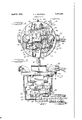
Figure 1 isasideelevation, partly.- in section, of" the electrical and thermaltcontrolling apparatus mounted on a furnace wall;
Figure 2 is a frontelev-ation ofithe appara tus mounted on abase from which the enclose ing cover hasbeen removed;
Figure 3' is a planview: of: the apparatus;
Figured-is a section on-plane-IV- HZ of Figure 3';
Figure 5 is a section oniplane VV of igure l; and
Figure 6 is a diagram of the circuit connecting-the various-electrical and thermal elements.-
T he electrical, thermal, andother; elements forming part of my improved. control: are compactly mounted on a" base lOwhichi-s preferably of'insulating material and to the bacl: of which is secured a supporting block or frame 11 having'the cylindrical opening 12 for receiving the cylindricalouterend ofa tubular frame 13. As shown in Figure- 1', this tubular frame extends: through an opening 1% in the wall 15 offthefurnacetobe supplied, andthe frame has a flange 16 byv 1930; Serial 3T0. 4 58,2421.
which it is rigidly secured to the frame 11 is split, as clearly shown i 3. and 4 and receives a screw 17 by means oi'which the frame may be securely contractedaround the tubular frame 13 to dly secure the frames together.
The frame 11 is mounted a distance above the center of the base 10 which is cylindrical, and extending through th frame 11 and the base 10 is the shaft 18, the frame 11 forming a bearing for the shaft.
An inverted U- shaped bracket 19 is secured to the front side of the base 10 and extends downwardly to receive the shaft 18 at an intermediate point to form a bearing support therefor.
Extendin from the outer end of the shaft Sis a couplingsleeve 20 having channels or slots 21 for receiving the outer splined end of a rod 2 which extends inwardly through he frame 13 andis secured to the inner end Response of'the thermostat element 23 to temperature changes will result in rotation of, the rod 22 and of'the shaft 18.
Mounted on the shaft 18 just outside of the bracket 19 is a setting member or frame 25, Jreferably ofinsulatingmaterial, which frame, above the shaft, has the slit 26 and receives a screw :27 so that the frame may clamp the-shaft-with more or less friction, in order that, when the frame is unobstructed, rotation of the shaft will rotate the frame, but when the frame is stopped, the shaft may continue to rotate. This isfor the purpose of relieving the thermostat element 23 from strain and to permit further contraction or expansion thereof after ithasserved the purpose of rotating the shaft to position the setting member.
at itslower end, the setting frame is cut away to leave the opposed legs 28 and 29. The 16,9,528 supports an adjustable contact screw 30 having a contact, point 31, while the leg 29 supports an adjustable stop screw 32.
Mountedon the shaft 18 between the outer wallof the bracket 19 and the base 10 isa switch member or frame 33 which may freely tube and will rotate on the shaft and whose longitudinal movement is restrained by the bracket 19 and the collar 34 on the shaft. The frame has the depending arm 35 from which the contact post 36 extends into position between the contact point 31 and the stop screw 32 on the setting member 25. Above the shaft 18, the switch frame 33 has the transverse bore 37 for receiving the closed tube 38 containing a ball weight 39. The frame above the tube is split and is drawn together by a screw 40 to securely clamp and hold the tube. The tube extends beyond each side of the frame and, when the frame is swung, the ball will move to the lower end of the tube and will tend to hold the frame in its swung position.
The setting frame 25 has a weight 41 secured thereto on the side from which the leg 28 extends which supports the contact 31, so that the frame will tend to rotate to carry the contact point 31against the terminal post 36 and to swing the switch frame 33 beyond its center line so that the ball will roll in the tend to hold the switch frame with he terminal post against the stop screw 32. The swing of the setting frame 25 is limited by stop screws 42 and 43 threading through the top of the bracket 19. The adjustment of the screw 43 is such that the setting frame 25 may be swung by its weight 41 a distance sufficient to swing the switch frame 33 beyond its neutral line so that the ball weight 39 may continue the movement of the switch frame to'carry the contact post 36 against the stop screw 32 and away from the contact point 31. The stop screw 42 permits rotation of the setting frame in the opposite direction a sufficient distance to swing the switch frame through its neutral line so that the ball weight may then continue the movement of the switch frame to carry the terminal post 36 away from the stop screw 32 and against the contact point 31.
The arrangement of the thermostat element 23. is such that, when it becomes cool, it will cause rotation of the rod 22 in counterclockwise direction (Figure 2). Rotation of the rod 22 will rotate the shaft 18, and the frictional engagement of the shaft 18 with the setting member, assisted by the weight 41 on the setting member, will swing this member in counterclockwise direction, this resulting, as has just been explained, in swinging the switch frame 33 to carry the terminal post 36 away from the contact point 31 and against the stop screw 32. When the thermostat element 23 is heated, the rotation of the shaft 18 will be in the opposite direction and against the weight 41, and the terminal post on the switch frame will be moved away from the stop screw 32 and against the terminal point 31. After swing of the setting member'to either of the setting positions, the shaft 18 may continue to be rotated by the thermostat element on account of the friction and the strip 47 mav engagement between'the shaft 18 and the setting member.
It will be noted that, although the setting member 25 may be comparatively slowly swung, the switch frame 33, after being carried through its neutralline by the setting member will then be rapidly swung by the ball weight into either of its positions to thus cause quick make and break of circuits to be controlled and to reduce to a minimum any sparking between the terminal post 36 and the contact point 31.
Mounted to freely rotate on the shaft 18 in frontof the setting member 25 is a block 44 of insulating material which forms part of safety switch mechanism. The block is restrained against extended longitudinal movement on the shaft by a washer 45 and a collar 46. The shaft 18 receives the block at one side thereof, so that the right end of the block (Fig. 2) is heavier and tends to swing the block in clockwise direction.
Extending across the front of the block 44 is a bi-metallic, thermal-responsive strip 47 which extends from the front leg of a U- shaped supporting bracket 48 secured by its rear leg to the rearside of the block. This bracket 48 is also formed .of a bi-inetallic, thermal-responsive strip, but the arrangement is such that the thermal response of the strip 47 and bracket 48 will be in opposed directions in order that any tendency of the strip 47 to respond to ordinary atmospheric changes of temperature will be counteracted by the response of the bracket 48 to such temperature variations. The supporting connection between the bracket 48 d be by means of a small block 49 (Fig.
A heater structure is secured to the bi-metallicelement 47' and comprises a block of insulating material 50 clamped against the front face of the element by screws 51 and a bar 52 engaged across the back of the strip. The block has grooves supporting a heating coil 53, and aplate of mica or other insulating material 54 is interposed between the block and the strip to prevent electrical contact of the coil with the strip. The block has terminal screws 55 and 56 receiving the ends of the heating coil so that it may be readily connected in circuit. The bi-m tallic strip 47 is so arranged that, when heated by the heating coil, it will flex forwardly.
Extending forwardly from the left side of the setting member 25 is an arm 57 having a vertical slot 58 at its outer end for receiving the end of the bi-metallic element 47 to limit the deflection thereof. Threading through the'arm 57 is a rod 59 whose outer end projects a distance into the slot 58 to be aoove the free end of the bi-metallic element 47 when such element is deflectedinwardly, so that this rod will thus form a'stop to prevent swing of the block 44 by gravity and independently of the swing of the setting member 25. When the bi-nietallic element is deflected forwardly upon being heated by the heating coil, it will release itself from the rod, so that the unbalanced block 44 will rotate clockwise (Fig. 2).
On top of the block 44 a U-shaped switch spring is secured, by its shorter leg by means of a. screw 61 extending through the block. The upper longer leg of the spring extends laterally across the block and near its free end has a contact point 62 for contacting with a terminal contact 63 at the end of a bolt 64 extending through the block (Fig. 2). The switch spring is tensioned so that, when unrestrained, it will hold its contact 62 against the terminal contact 63. However, when the block 44 is rotated independently of the settin member 25, the free end of the switch spring will encounter a post 65 projectingforwardly from the adjacent end of the m mber 25, and the switch spring will then be restrained while the block 44 continues its rotation, and the spring contact will be separated from the terminal point 63, as shown in Figure 5. The post 65 may serve also as a stop to be engaged by the bi-metallic member 48 on the block 44 to limit the of the block in counterclockwise direction, while post 66 extending forwardly from the setting member 25 will be engaged by the member 48 to limit the clockwise rotation of the block 44. It will be noted that, when the bi-metallic element 47 is deflected forwardly to unlatch itself from the rod 59, and the block 48 rotates, the element will remain in front of the rod so that, when it is deflected rearwardly upon cooling, it will engage its inner face against the end of the rod, so that, when the block 48 is restored, the element will pass along the end of the rod and will then swing back into latching position under the rod.
Referring to Fi ure 1, a protecting housing 67, which may be in the form of a metal shell, is provided for the apparatus and seats on the base 10 and is detachably secured by means of thumb screws 68. Pivoted to the outer wall of the housing is a resetting lever 69 which be turned y means of a button 68 to engage its end 69 against the right end of the bi-metallic structure to thereby swing the block 44 in counterclockwise direction to reset the bi-metallic element 47 in latching engagement with the rod 59.
On Figure 6,1 diagrammatically represent the various operating elements of the control and the electrical circuit connection therefor. The supply conductors 70 and 71 are connected by a line switch 7 2 with a current supply circuit 73. The conductors 7 0 and 71 extend through a pipe fitting 74' and connect respectively with the terminal posts 74 and 7 5 mounted on the base 10. The terminal post 76 on the base is connected by conductor 77 with the screw 30 which terminates in the contact point 31. This contact point is connected by a conductor 7 8 with the terminal 55 of the heating coil 53, whose other terminal 56 is connected by a conductor 79 with the terminal screw 61 connecting with the switch lever 60. This terminal screw 61 is connected by a conductor 80 with the binding post 81 on the base '10. A conductor 82 c0nnects this binding post with the terminal post 36 on the switch frame 33. The terminal screw 64, terminating in the contact point 63 for the switch lever 60 is connected by conductor 83 with the terminal post 74 on the base 10.
The motor M for driving the means for projecting the oil or gas into the furnace is connected by conductors 84 and 85 with the terminal posts 75 and 76 on the base 10, and a transformer T for producing ignition sparks the points 86 is connected by conductors 87 and 88 with the binding posts 7 5 and 81 on the base 10.
The spark points 86 are located to ignite the gas or vapor issuing from the burner or nozzle in the furnace, and the thermostat element 23 is located in close proximity to the burner or nozzle so as to be subjected to the heat therefrom after ignition takes place. A house thermostat 89 of any of the welllrnowntypes may be included in one of the supply conductors, and, where the heating device is a boiler, a suitable device 90 may be included in the circuit for automatically opening the supply circuit as, for example, when the boiler water falls below a certain predetermined level, or when the steam temperature or pressure reaches a certain predetermined maximum.
Describing now the operation, suppose that the heating device to be served is cold. When the thermostat element J3 cooled after its last heating, it rotated the shaft 18 in counterclockwise direction (Fi to swing the setting member 25 in the same direction and to thereby cause swing of the switch frame 25 by the ball weight 27 to disengage the contact post 86 from the contact point 31 and to hold it against the stop 32, as shown in Figure 2. lVhen the line switch 7 2 is now closed, current will flow through the conductor 70, the control devices 89 and 90, conductor 83 to the contact point 63 of the safe ty swi ch, and, this switch is at this time latched in normal position by the rod 59, the current will continue through the switch contact 62 and the switch sjring 60, then through the heating coil conductors 78, 77 and 85 to the motor M, and from the motor through conductor 84 to the supply conductor 71. The motor will now set the oil or gas delivery apparatus in operation. At the same time, a branch circuit delivers current through the transformer T, this circuit e2:-
tending fronrthe binding post 74 through,
The current low through the heating coil generates heat which is transmitted to the binetallic thermostat element 47 which there upon starts to flex forwardly, but, if everything is in proper condition, the main thermosta-t element 23 will respond more quickly to the heat of the furnace and will cause rotation of the shaft 18 in clockwise direction (Fig. 2), so that beforethe thermostat clement l? becomes effective to'uniatch the switch block a l, the setting member 25 will berotated in clockwise direction by the sha t 18 to cause swing of the switch member 25 to carry its terminal post 36 into engagement with the contact point 31, and then the short circuit comprising the conductors 80, 82 and 77, is closed around the heating coil,
which, being then deprived of its current heated to unlatch itself.
flow, will cool ofi so that the thermostat el ment at? will be held latched. The switch 60 which is included serially in the supply c1r- Qcuit will then remain closed and current will continue to flow through the motor. i hen this short circuit is closed,the transformer will be directly bridged around the motor and will continue to receive current flow for V A supplying ignition sparking. 3.3
upon such swing, the end of the safety switch will encounter the stop post and the terminal 63 will be withdrawn from the switch contact 62 and the supply circuit to the motor will be opened, so that further supply of gas or oil to the heating device will be stopped. For example, the motor might start after closure of the supply circuit by the line switch 72, but the transformer would fail to function. The gas or oil delivered to the furnace would then not be ignited and the main thermostat element 23 would not be heated, and flooding or gas accumulation would result, and there might be a violent explosion should the spark suddenly become operative. However, as explained, failure of the thermostat 23 to function will keep the heater coil effective and the safety switch structure ill become unlatched and will cause opening of the supply circuit for the motor, which then stops;
It might also happen that, after a period of efficient operation of the heating device and control apparatus, the flame would become extinguished, as, for example, by the failure of proper oil or gas supply to the burner ornozzle. The main thermostat element 23 would then cool and set the control apparatus to effect opening of the short cirrod 22 and, consequently, from the shaft 18. Under these conditions, the weight ll on the setting member 25 will swing the set ting member and cause disconnection of the switch member 25 irom the contact point 31, so t the short circuit around the heating coil will be opened and the coil will function to supply heat to cause unlatching of the safe ty switch, with consequent opening of the motor supply circuit.
it is understood, of course, that the house thermostat 89 will open the motor supply circuit when the temperature in the room reaches tie predetermined maximum, and likewise, the control device 90 will open the motor supph circuit, as for example, when the water in the boiler becomes too low for the steam temperature or pressure reaches a predetermined maximum.
My improved burner control is of simple and compact arrangement, and the various parts therefor can be'econcmically manufactured and assembled. It will be noted that delicate switch elements, such as mercury switches, have been eliminated, and simple, rugged and durable circuit-controlling or switch elements have been provided. The easily rotatable switch member 25, which controls the short circuit for the heating coil causes quick make and break of the controlling circuits by means of the ball weight 27. Likewise, the overbalanced safety switch structure a l, when unlatched, quickly breaks the motor supply circuit. in my improved control apparatus, the parts therefor accu- Ele13 retain their adjusted conditions and cannotreadily become out of order.
it is evident, of course, that changes and modifications, both in construction, arrange ment and operation, may be made without departing from the scope and principles of the invention, and I, therefore, do not desire l I. I L
to so limited except as is spec fied in the appended claims.
I claim as follows:
1. In a switch mechanism, the combinat'o of a shaft, a setting member mo shaft to rotate therewith, abutr said setting member, a switch me ed on said shaft to swing free having a circuit contact exte between said abutment arms, 1' setting member causing engagement abutment arms with said contact to swing of said switch member to a neutral line, means associat switch member for continu' thereof after setting member, and a con ment arms for cooperating i member contact.
2. In a switch mechaof a rotatable shaft s ed on said shaft to tate switch structure necting saio er: said settin +1, out:
comb i u atic-n lbch. member, ally structure from sid for swinging said un independently of abutment in the path 0" engagement of said said abutment.
3. In a switch mech nism, the comb uati on of a shaft, a setting member met 1 tate with said shaft, a switch bl-O mechanism normally connec to rotate with said setting in actuated means for means tending to swi block, a switch mounted on c U 7 an abutment on said setting member on by said switch when said block rotfi thereby cause actuation of said switch.
4:. In a switch mechanism, the combination of a shaft, a setting member mounted to rotate with said shaft, a switch frame piv oted adjacent to said setting element, said frame being overbalanced and tending to swing in one direction relative to said setting member, a latch projection on said setting member, a thermostatic latch member normally engaging said latch extension to hold said frame f om swinging, an electrical he 1 ing element for said thermostatic lat i A- g member, heating of said latch member causing disengagement thereof from said latch projection thereby permitting rotation of said frame, a switch on said switcn frame, and an abutment on said setti gaged by said switcn when t to thereby cause actuation of said sw'" V 5. In a switch mechanism, the combition of a pivoted frame, said frame overbalanced and tending to swing wardly, a thermostatically controlle normally holding said frame up, thermal means responsive to current flow for heating said thermostat latch mechanism to cause unlatching of said frame whereby said frame will swing downwardly, a circuit terminal on said frame, a switch spring mounted on said frame and normally engaging said circuit terminal, and an abutment in the path of said spring engaged thereby when said frame swings to be thereby separated from said terminal contact.
6. in a switch mechanism, the combination of a rotary shaft, a thermostat member responsive to changes in temperature to rotate said shaft, switch mechanism actuated by the rotation of said shaft, an auxiliary switch and a pivoted supporting frame therefor, said frame being overbalanced and tend ing to swing downwardly when released, a thermostat controlled latch normally holding said frame up, a heating coil responsive to current flow for heating said thermostat latch controlling mechanism to cause unlatching of said frame, a short circuit closed around said heating coil when said shaft controlled switch mechanism is actuated by the rotation of the shaft in one direction, said short circuit being opened when said shaft is rotated in the opposite direction, said auxiliary switch being closed when said frame is held in latched position, and an abutment cooperating with said auxiliary switch to cause opening thereof when the unlatched frame swings down.
7. In a switch mechanism, a rotary element, a member movable by said element including a contact on one side of the element and tilting means on the other side of the element for forcing said contact into either one of two positions, contact means for engaging said contact when it is in one of said positions, switch means associated with said element and electro-thermal means for opening said switch means upon a failure of said element to move said contact to the position in which it is in engagement with said contact means.
8. In a switch mechanism, a rotary ele ment, a member movable by said element including a contact on one side of the element and tilting means on the other side of the element for forcing said contact into either one oftwopositions, contact means for engaging said contact when it is in one of said positions, switch means associated with said element and electro-thermal means for opening said switch means upon a failure of said element to move said contact to the positi on in which it is in engagement with said contact means, said tilting means including a tube having therein a ball rollable in said tube over the axis of said element to effect movement of said contact.
9, In switch mechanism, a rotary element, member movable by said element including a contact on one side of the element and tilting means on the other side of the element for forcing said contact into either one of two positions, contact means for engaging said contact when it is in one of said positions, switch means associated with said element and electro-thermal means for opening said switch means upon a'failure of said element to move said contact to the position in which it is in engagement with said contact means, said electro-thermal means including a bi-metallic latch for normally maintaining said switch means in a closed position and a heatercoil for releasing said latch to permit of the opening of said switch means.
10. In a switch mechanism, a rotary element, a member movable by sald element 1ncluding a contact on one side of the element and tilting means on the other side of the element for forcing said contact into either one of two positions, contact means for engaging said contact when itis in one of said positions, switch means associated with said element, electro-thermal means for opening said switchmeans upon a failure of said element to move said contact to the position in which it is in engagement with said contact means, and manual means for closing said switch means upon an opening of the same by said electro-thermal means.
In testimony whereof I have hereunto subscribed my name atChicago, Cook County,
CHARLES L. RAYFIELD.
Illinois.
Priority Applications (1)
| Application Number | Priority Date | Filing Date | Title |
|---|---|---|---|
| US458241A US1851983A (en) | 1930-05-31 | 1930-05-31 | Burner control |
Applications Claiming Priority (1)
| Application Number | Priority Date | Filing Date | Title |
|---|---|---|---|
| US458241A US1851983A (en) | 1930-05-31 | 1930-05-31 | Burner control |
Publications (1)
| Publication Number | Publication Date |
|---|---|
| US1851983A true US1851983A (en) | 1932-04-05 |
Family
ID=23819953
Family Applications (1)
| Application Number | Title | Priority Date | Filing Date |
|---|---|---|---|
| US458241A Expired - Lifetime US1851983A (en) | 1930-05-31 | 1930-05-31 | Burner control |
Country Status (1)
| Country | Link |
|---|---|
| US (1) | US1851983A (en) |
-
1930
- 1930-05-31 US US458241A patent/US1851983A/en not_active Expired - Lifetime
Similar Documents
| Publication | Publication Date | Title |
|---|---|---|
| US4360338A (en) | Control system for dual coil pilot valve burner system | |
| US2089081A (en) | Safety control mechanism | |
| US2216748A (en) | Thermal electric switch | |
| US1851983A (en) | Burner control | |
| US2195649A (en) | Oil burner | |
| US3484177A (en) | Igniter and control means | |
| US2510265A (en) | Ignition and control system for fuel burners | |
| US2261586A (en) | Control system for fluid fuel burners | |
| US2154644A (en) | Safety control system | |
| US2398215A (en) | Safety control apparatus for gaseous fuel burners | |
| US1793011A (en) | Automatic oil-burner-control system | |
| US2113858A (en) | Control unit | |
| US2399673A (en) | Control system | |
| US2503259A (en) | Lost motion control system | |
| US2012322A (en) | Automatic control of combustion | |
| US3138194A (en) | Multiple burner heating system | |
| US3115180A (en) | Remote reset safety control for gaseous fuel burners | |
| US1969967A (en) | Burner control apparatus and system | |
| US2254984A (en) | Burner control system | |
| US1908009A (en) | Electrical switch and control circuit therefor | |
| US2194245A (en) | Fuel burner control system | |
| US2185317A (en) | Control apparatus | |
| US2355309A (en) | Automatic burner control system | |
| US1883246A (en) | Electrical switch and control circuit therefor | |
| US4255118A (en) | Electric ignition system |