US1851972A - Printing press sheet delivery frame - Google Patents
Printing press sheet delivery frame Download PDFInfo
- Publication number
- US1851972A US1851972A US373960A US37396029A US1851972A US 1851972 A US1851972 A US 1851972A US 373960 A US373960 A US 373960A US 37396029 A US37396029 A US 37396029A US 1851972 A US1851972 A US 1851972A
- Authority
- US
- United States
- Prior art keywords
- frame
- walls
- sheets
- printing press
- sheet
- Prior art date
- Legal status (The legal status is an assumption and is not a legal conclusion. Google has not performed a legal analysis and makes no representation as to the accuracy of the status listed.)
- Expired - Lifetime
Links
- 239000002184 metal Substances 0.000 description 3
- 238000010276 construction Methods 0.000 description 2
- 229940000425 combination drug Drugs 0.000 description 1
- 230000005611 electricity Effects 0.000 description 1
- 239000000463 material Substances 0.000 description 1
- 230000004048 modification Effects 0.000 description 1
- 238000012986 modification Methods 0.000 description 1
- 238000010008 shearing Methods 0.000 description 1
- 230000003068 static effect Effects 0.000 description 1
- 210000002105 tongue Anatomy 0.000 description 1
- 238000009423 ventilation Methods 0.000 description 1
Images

Classifications
-
- B—PERFORMING OPERATIONS; TRANSPORTING
- B65—CONVEYING; PACKING; STORING; HANDLING THIN OR FILAMENTARY MATERIAL
- B65H—HANDLING THIN OR FILAMENTARY MATERIAL, e.g. SHEETS, WEBS, CABLES
- B65H31/00—Pile receivers
-
- B—PERFORMING OPERATIONS; TRANSPORTING
- B41—PRINTING; LINING MACHINES; TYPEWRITERS; STAMPS
- B41F—PRINTING MACHINES OR PRESSES
- B41F23/00—Devices for treating the surfaces of sheets, webs, or other articles in connection with printing
- B41F23/04—Devices for treating the surfaces of sheets, webs, or other articles in connection with printing by heat drying, by cooling, by applying powders
- B41F23/044—Drying sheets, e.g. between two printing stations
- B41F23/0443—Drying sheets, e.g. between two printing stations after printing
Definitions
- This invention relates to improvements in printing presses and more particularly to devices receptive of the printed sheets as delivered from the press.
- Such sheets freshly printed upon one or both'sides, are commonly passed over a zone of heat, as a pluralit of small gas flames, or an electric heater unlt, to oxidize the surface of the ink, and also to dispel inherent static electricity in the sheets which advance to become stacked in a pile at the end of the press, ready for further operations.
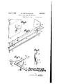
- Figure 1 is a plan view of an embodiment of the invention as attached for operation.
- Figure 2 is a transverse sectional view taken on line 22 of Fig. 1, showing the sheets as deposited.
- Figure 3 is a perspective view of one of the adjustable side walls as attached to a support bar, showing the adjustable open corner.
- Figure is a similar view showing a support bar and its connections to a j oggle rod.
- Figure 5 is a like view of an independent i bar attaching device.
- Figure 6 is a fragmentary perspective view showing an attaching clip formed on one of the frame walls.
- -A printed sheet receiving table 10 see Fig. 2, forming part of the press, such as the Babcock or like type, is provided with means for height adjustment and spaced adjacent the corners of the tableare four posts 11, surmounted by rigid brackets 12, 13, 14 and 15 extending towards the center line of the table, the bracket 15 having an arm 15" extending angularly outward and rearward or towards the direction from which the printed sheets are delivered from the press.
- J ournalled inthe end of the arm 15' is an upright shaft 16 to which is communicated a semi rotary motion reciprocatively'by some convenient means, as part of the press.
- a lever 17 Fixed on the upperend of the shaft 16 is a lever 17 having pivotally attached at its end a horizontal rod 18, its forwardly extending end pivotally engaging an angular arm 19 of a double bell-cranklever having.
- a similar lever having opposed arms 23 24 and a right angled arm 25 ispivoted at 26 to the bracket 12.
- a connecting rod 27. is pivoted to the arms 21 and 23 and a similar rod 28 connects the arms 20 and 24, these rods extending in parallel transversely across the front of the press.
- a third double bell-crank lever pivoted at 30 to the bracket 15 has an angular arm 31 pivoted to the rod 18 its opposed arms 32-33 are connected by rods 34-35 to the arms 36-37 of a fourth double bell-crank lever, pivoted at 38 to the bracket 14 and its angular arm 39 is engaged by :a connecting rod 40 with the arm 25.
- a pair of studs 41-42 are fixed respectively in the brackets 1218 to extend horizontally towards the front and slidably engaged on the studs are sheet metal spring clips 43, each comprising a pair of divergent arms 44 containing slightly oversized openings through which the studs freely pass when the arms are pressed inward to permit adj ustment of the clip, the arms springing out when released to firmly grip the stud.
- These clip arms are integrally connected by a body member 45 having a raised portion 46 containing a rectangular opening closely fitting a rectangular bar 47 in a plane above the studs and which may thus be adjusted with relation to the sheet as delivered into the enclosure.
- Another pair of duplicate clips 43 are adjustable on the rods 1840, to carry a bar 48 parallel with the bar 47
- still another pair of clips carry a bar 49 by their connection with the rods 28-35 movable coincidentally with, but oppositely to the rods 727-34.
- a pair of thin sheet metal plates 5050 constitutesectionsof the front and rear memformed by shearing and upsetting, to receive the plate portions of sheet metal spring clips having tongues 56 formed to present gripping means, as at 57, to engage the rectangular support bars 47-48.
- the clips are struck directly from the walls of the frame to present a spring portion 56 and a grip 57 through which the bars may be passed.
- the end walls 5859 of the frame may also be formed in sections, these walls being provided with similar spring clips 56 to engage the support bars.
- the end walls 58-5 9 may have more movement transmitted to them, as will be evident, their inward motion taking place as the sheets are settling down, thus moving them endwise into registration. It is also within the scope of the invention to dispense with all movement of the frame walls.
- the elements 54 and 56 admit of ventilation, releasing the entrained hot air and it is within the scope of the invention to provide specific. ventilating openings, although the spaced corners in practice have been found completely effective for the purpose.
- a printed sheet receiving frame comprising four upright walls forming a rectangle, each wall being composed of sections adjustable in length and arranged to present clearly open spaces at each of their corner intersections.
- a printed sheet receiving frame having relatively adjustable walls spaced at their. corners, support bars arranged in parallel relation to said walls and slidably engaged thereto, and clips adjustably connecting said bars to supports.
Landscapes
- Engineering & Computer Science (AREA)
- Mechanical Engineering (AREA)
- Registering Or Overturning Sheets (AREA)
- Pile Receivers (AREA)
Description
April 5, 1932. H. c. BLAUVELaT ET AL 1,851,972
PRINTING PRESS SHEET DELIVERY FRAME Filed June 27, 1929 2 Sheets-Sheet l x INVENTOR, ouv dmad/fi B wan/um a MM.
ATTORNEY April 5, 1932. H. c. BLAUVELT ET AL 1,351,972,
PRINTING PRESS SHEET DELIVERY FRAME Filed June 27, 1929 2 Sheets-Sheet 2 55M 4mm INVENTORS LU k oRNEY' Patented Apr. 5, 19323 UNITED STATES PATENT. OFFICE HARRY GOE BLAUVELT, OF NEW YORK, AND JOHN EDWARD'SCHELBERG, OF ROSEDALE', I,
. NEW YORK PRINTING PRESS SHEET DELIVERY FRAME.
Application filed .Tune 27,
This invention relates to improvements in printing presses and more particularly to devices receptive of the printed sheets as delivered from the press.
Such sheets, freshly printed upon one or both'sides, are commonly passed over a zone of heat, as a pluralit of small gas flames, or an electric heater unlt, to oxidize the surface of the ink, and also to dispel inherent static electricity in the sheets which advance to become stacked in a pile at the end of the press, ready for further operations.
In practice it is often found necessary to interpose slip sheeting betweenthe printed sheets to prevent offsetting or transference of some of the ink from the face of the lower sheet to the back of the next above, although the ink will at times stick to the slip sheets and cause offset on the work.
It is also desirable that the pile of printed sheets be stacked uniformly with the edges of eachsheet in register throughout."
Various expedients have been'devisedto attainthese purposes, such for instance as closedframe structures in which the sheets float on a film of air entrained under their lower surfaces and fallslowly as the air escapes at their-edges, the corners of the sheets descending slower than their main portions. It is an object of the presentinventionto provide an adjustable enclosure having quite high."walls, each sidebeing adjustable in length to enclose the printed sheets with a minimum of space at their edges, and which are arranged to present open corners, adjustable in extent to suit the'size and weight of the paper used, so that the sheets passing over the heated zone with hot air entrained,
1929. Serial No. 373,960.
means for ad ustably attaching 1 the frame walls to support bars commonly provided with the press.
These several important objects are accom-, plished by the novel construction and com bination of parts hereinafter described and illustrated in the accompanying drawings, forming a material part ofthis disclosure, and in which Figure 1 is a plan view of an embodiment of the invention as attached for operation.
Figure 2 is a transverse sectional view taken on line 22 of Fig. 1, showing the sheets as deposited.
Figure 3 is a perspective view of one of the adjustable side walls as attached to a support bar, showing the adjustable open corner.
Figure is a similar view showing a support bar and its connections to a j oggle rod.
Figure 5 is a like view of an independent i bar attaching device.
Figure 6 is a fragmentary perspective view showing an attaching clip formed on one of the frame walls.
, -A printed sheet receiving table 10, see Fig. 2, forming part of the press, such as the Babcock or like type, is provided with means for height adjustment and spaced adjacent the corners of the tableare four posts 11, surmounted by rigid brackets 12, 13, 14 and 15 extending towards the center line of the table, the bracket 15 having an arm 15" extending angularly outward and rearward or towards the direction from which the printed sheets are delivered from the press.
J ournalled inthe end of the arm 15' is an upright shaft 16 to which is communicated a semi rotary motion reciprocatively'by some convenient means, as part of the press.
Fixed on the upperend of the shaft 16 is a lever 17 having pivotally attached at its end a horizontal rod 18, its forwardly extending end pivotally engaging an angular arm 19 of a double bell-cranklever having. two
opposed arms 2021 respectively, the lever being pivoted at 22 on the bracket 13.
as integrally.
A similar lever having opposed arms 23 24 and a right angled arm 25 ispivoted at 26 to the bracket 12. A connecting rod 27. is pivoted to the arms 21 and 23 and a similar rod 28 connects the arms 20 and 24, these rods extending in parallel transversely across the front of the press.
A third double bell-crank lever pivoted at 30 to the bracket 15 has an angular arm 31 pivoted to the rod 18 its opposed arms 32-33 are connected by rods 34-35 to the arms 36-37 of a fourth double bell-crank lever, pivoted at 38 to the bracket 14 and its angular arm 39 is engaged by :a connecting rod 40 with the arm 25. I M
It will now be apparent that the rods 18 and 40, at the ends of the table will move in unison in the same direction, also the rod 28 and 35, while at the same time the rods 27 and 34 move in unisonin opposite directions coincidentally.
A pair of studs 41-42 are fixed respectively in the brackets 1218 to extend horizontally towards the front and slidably engaged on the studs are sheet metal spring clips 43, each comprising a pair of divergent arms 44 containing slightly oversized openings through which the studs freely pass when the arms are pressed inward to permit adj ustment of the clip, the arms springing out when released to firmly grip the stud.
, These clip arms are integrally connected by a body member 45 having a raised portion 46 containing a rectangular opening closely fitting a rectangular bar 47 in a plane above the studs and which may thus be adjusted with relation to the sheet as delivered into the enclosure.
Another pair of duplicate clips 43 are adjustable on the rods 1840, to carry a bar 48 parallel with the bar 47 Other clips, attached to the rods 2734, adjustably carry a bar 49, and still another pair of clips carry a bar 49 by their connection with the rods 28-35 movable coincidentally with, but oppositely to the rods 727-34.
It is to be understood that the foregoing description of jogger frame structure will apply to a certain make of press, while other presses may vary considerably in detail, but all presses to which the device is applicable are provided with some means for carrying the four support bars; it will be further understood that thejogger device is not a part of the present invention, which consists of a sheet enclosing frame now to be described.
A pair of thin sheet metal plates 5050 constitutesectionsof the front and rear memformed by shearing and upsetting, to receive the plate portions of sheet metal spring clips having tongues 56 formed to present gripping means, as at 57, to engage the rectangular support bars 47-48.
In the modification showing Fig. 6 the clips are struck directly from the walls of the frame to present a spring portion 56 and a grip 57 through which the bars may be passed.
The end walls 5859 of the frame may also be formed in sections, these walls being provided with similar spring clips 56 to engage the support bars.
As the extent of joggling the frame front walls 5052 is very little, being limited by are of the angular levers 19253139, and the rear walls 50-52 are held fixed by the bar 47, these walls may be adjusted in length to conform with the length of the paper sheet to be printed.
The end walls 58-5 9 however may have more movement transmitted to them, as will be evident, their inward motion taking place as the sheets are settling down, thus moving them endwise into registration. It is also within the scope of the invention to dispense with all movement of the frame walls.
In any case, when the frame walls are in their closed position, spaces 60 are adjustably maintained at each corner of the frame, and this adjustment should be made in accordancewith the speed of reception of the sheets from the press, the weight of the paper andthe size of the sheet, the preferred arrangement being that several of the sheets are floating on intermediate air cushions as they are deposited on the table in a pile as seen in Fig. 2. j j p The wall 50-52 acts as a stop against which the front edges of the sheets make contact, while the end walls, due to their reciprocative movement, causes the end edges to assume an accurately alined position as they are deposited.
It is further to be noted that the elements 54 and 56 admit of ventilation, releasing the entrained hot air and it is within the scope of the invention to provide specific. ventilating openings, although the spaced corners in practice have been found completely effective for the purpose.
From the foregoing it will be seen that a simple device for this purpose has been disclosed in the preferred form of its embodiment, but it is not desired to restrict the de tails to the exact construction shown, it being obvious that changes, not involving the exercise of invention, may be made without conflicting with the scope of the appended claims.
Having thus described the invention, what is claimed as new and desired to secure by Letters Patent, is
1. A printed sheet receiving frame comprising four upright walls forming a rectangle, each wall being composed of sections adjustable in length and arranged to present clearly open spaces at each of their corner intersections.
2. A printed sheet receiving frame having relatively adjustable walls spaced at their. corners, support bars arranged in parallel relation to said walls and slidably engaged thereto, and clips adjustably connecting said bars to supports.
3. The combination with the jogger frame of a printing press and a sheet receiving table, of a frame adjustable to the size of a printed sheet and open at its corners, clips on the outer surfaces of the frame walls, rectangular bars adjustably engaged in said clips, and adjustable connections between said bars and said jogger frame.
4. The combination with the jogger frame of a printing press and a sheet receiving table, of an upright rectangular frame having length adjustable walls level on the inner sides, integral clips on the outer sides of said walls, bars slidable in said clips, spring clips adjustably connecting said bars with said jogger frame, and means to ventilate the rectangular frame at its walls intersections.
In testimony whereof we afiix our signatures.
HARRY COE BLAUVELT. J OHN EDWARD SCHELBERG.
Priority Applications (1)
| Application Number | Priority Date | Filing Date | Title |
|---|---|---|---|
| US373960A US1851972A (en) | 1929-06-27 | 1929-06-27 | Printing press sheet delivery frame |
Applications Claiming Priority (1)
| Application Number | Priority Date | Filing Date | Title |
|---|---|---|---|
| US373960A US1851972A (en) | 1929-06-27 | 1929-06-27 | Printing press sheet delivery frame |
Publications (1)
| Publication Number | Publication Date |
|---|---|
| US1851972A true US1851972A (en) | 1932-04-05 |
Family
ID=23474638
Family Applications (1)
| Application Number | Title | Priority Date | Filing Date |
|---|---|---|---|
| US373960A Expired - Lifetime US1851972A (en) | 1929-06-27 | 1929-06-27 | Printing press sheet delivery frame |
Country Status (1)
| Country | Link |
|---|---|
| US (1) | US1851972A (en) |
Cited By (5)
| Publication number | Priority date | Publication date | Assignee | Title |
|---|---|---|---|---|
| US2595437A (en) * | 1946-09-20 | 1952-05-06 | Southworth Machine Co | Sheet jogging mechanism for printing presses |
| US2980272A (en) * | 1957-08-07 | 1961-04-18 | Alexander V Wedensky | Hamper receiving and squaring apparatus |
| US3111233A (en) * | 1958-09-19 | 1963-11-19 | Mathews Conveyer Co | Pallet loading machine |
| US3380598A (en) * | 1966-04-11 | 1968-04-30 | Clayton J. Marschhausen | Retractable board holder for printing presses |
| US4023789A (en) * | 1974-02-07 | 1977-05-17 | Scott Paper Company | Method and apparatus for registering, feeding and separating original and copy sheets in a duplicator |
-
1929
- 1929-06-27 US US373960A patent/US1851972A/en not_active Expired - Lifetime
Cited By (5)
| Publication number | Priority date | Publication date | Assignee | Title |
|---|---|---|---|---|
| US2595437A (en) * | 1946-09-20 | 1952-05-06 | Southworth Machine Co | Sheet jogging mechanism for printing presses |
| US2980272A (en) * | 1957-08-07 | 1961-04-18 | Alexander V Wedensky | Hamper receiving and squaring apparatus |
| US3111233A (en) * | 1958-09-19 | 1963-11-19 | Mathews Conveyer Co | Pallet loading machine |
| US3380598A (en) * | 1966-04-11 | 1968-04-30 | Clayton J. Marschhausen | Retractable board holder for printing presses |
| US4023789A (en) * | 1974-02-07 | 1977-05-17 | Scott Paper Company | Method and apparatus for registering, feeding and separating original and copy sheets in a duplicator |
Similar Documents
| Publication | Publication Date | Title |
|---|---|---|
| US1851972A (en) | Printing press sheet delivery frame | |
| US1107859A (en) | Jogger for printing-presses. | |
| EP1652808B1 (en) | Sheet collecting device | |
| US1960697A (en) | Improved matrix former and drier | |
| FR2369193A1 (en) | SUCTION LEAF FLAPPING DEVICE | |
| GB1318756A (en) | Conditioning equipment for the copy paper supply in copyingmachines | |
| SE8504213D0 (en) | ARCH PRINTING MACHINE WITH ARCH INSTALLATION IN ONE PRESSURE MACHINE CYLINDER | |
| US3355167A (en) | Leveling platform with lift elements and dividers | |
| GB1035591A (en) | Improvements in heating units | |
| US1768498A (en) | Sheet-drying process anb apparatus | |
| US2660237A (en) | Vertical window shutter | |
| US1700990A (en) | Printer's frame | |
| US1574633A (en) | Printing-press attachment | |
| US1460260A (en) | Drying frame | |
| US624919A (en) | Rack for rubber stamps | |
| US724530A (en) | Combined printer's galley and chase. | |
| US1009459A (en) | Collector for printing-presses. | |
| US1866379A (en) | Chase for printing presses | |
| US1846158A (en) | Hot air blower | |
| GB407879A (en) | Improvements in and relating to sheet delivery apparatus particularly for printing machines | |
| US2863661A (en) | Interleaving device for a duplicating machine | |
| US360921A (en) | Paper-jogger | |
| US1777225A (en) | Printing machine | |
| USRE16036E (en) | Collating device for typewriters and adding machines | |
| US1321365A (en) | Btjrg |