US1851968A - Vehicle operated gate - Google Patents
Vehicle operated gate Download PDFInfo
- Publication number
- US1851968A US1851968A US478122A US47812230A US1851968A US 1851968 A US1851968 A US 1851968A US 478122 A US478122 A US 478122A US 47812230 A US47812230 A US 47812230A US 1851968 A US1851968 A US 1851968A
- Authority
- US
- United States
- Prior art keywords
- gate
- vehicle
- bar
- rods
- bars
- Prior art date
- Legal status (The legal status is an assumption and is not a legal conclusion. Google has not performed a legal analysis and makes no representation as to the accuracy of the status listed.)
- Expired - Lifetime
Links
- 208000027418 Wounds and injury Diseases 0.000 description 2
- 238000010276 construction Methods 0.000 description 2
- 230000006378 damage Effects 0.000 description 2
- 208000014674 injury Diseases 0.000 description 2
- 230000004075 alteration Effects 0.000 description 1
- 230000001174 ascending effect Effects 0.000 description 1
- 230000004048 modification Effects 0.000 description 1
- 238000012986 modification Methods 0.000 description 1
- 238000005728 strengthening Methods 0.000 description 1
Images
Classifications
-
- E—FIXED CONSTRUCTIONS
- E05—LOCKS; KEYS; WINDOW OR DOOR FITTINGS; SAFES
- E05F—DEVICES FOR MOVING WINGS INTO OPEN OR CLOSED POSITION; CHECKS FOR WINGS; WING FITTINGS NOT OTHERWISE PROVIDED FOR, CONCERNED WITH THE FUNCTIONING OF THE WING
- E05F13/00—Mechanisms operated by the movement or weight of a person or vehicle
- E05F13/04—Mechanisms operated by the movement or weight of a person or vehicle by platforms lowered by the weight of the user
Definitions
- My invention relates to new and useful improvements in vehicle-operated gates, and the primary object of my invention in this connection is the provision of a gate of this class which is opened bythe pressure of the wheels of the vehicle and closed by asuspended weight.
- Another particular object of lmy invention is the means employed for permitting the l wheels of the vehicle to bear against but without actually coming into Contact with the gate itself and for maintaining this contact until after the vehicle has passed beyond the ate.
- a further object of the invention resides in they means for preventing injury to the wheels of the vehicle when the gate is opened.
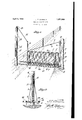
- Figure 1 is a perspective view of my improved gate in closed position, one of the posts which support the gate being partly broken away for the purpose of better illustration;
- Figure 2 is an enlarged vertical section through the gate, the view being had along the line 2 2 of Figure 1.
- 1 denotes the top bar, 2 the lower bar, and 3 and 4 the 5 vertical bars.
- a webbing 5 or other suitable material spans the space between the top, bottom and vertical bars and forms an oblong closure.
- the ends of the top and bottom rods 1 and 2 project beyond the vertical bar 3 and are secured to a larger vertically-disposed bar 6, the bars 1 and 2 being passed through the bar 6 and fastened thereto by the nuts 7
- the vertical bar 4 is extended upwardly above the bar 1 and forms a projection 8.
- a wire or rod 6 with a turnbuckle is connected to the projection 8 and to the top of the vertical bar.
- these bars may be of piping such 5 as shown in the drawings, or of any suitable material and in any thickness used. ingate structures. j
- the gate is closed and maintained in this position by a flexible element 14, loosely se-V cured to the upper end of the projection 8 and a weight 15 carried on the element ⁇ and disposed in the hollow post 16.
- a pulley 18 is rpflovided for the fiexible element 14.
- e form oy two parallel rods 19, one on eachv side of the gate, andk adjacent the bottom bar 2, and held in rigid and spacedrelation to the gate by the cross-rods 20.
- These rods 19 s project beyond ⁇ the front end of the gate, preferably passing underneath the fence A, and are providedat a point in line with the front right wheel of the vehicle with bumper rods 21.
- the bumper rods aremade to fit loosely ⁇ around the rods 19 so that they willrotate slightly when the ⁇ wheel of the vehicle strikes them and thus prevent injury to the tires or wheels.
- the rods 19 projecting beyond the front end of the gate will allow the :vehicle to pass, holding the gate open until the rear end of the vehicle is wellk past theswinging zone of the gate.V
- the pulley 18 is of the swivel type and permits the flexible element to move freely.l
- Suitable small posts are provided to limity the swinging movement of the gate in either direction as stops.
- the post 16 need not necessarily be hollow, as guide means may be provided to maintain the Weight 15 in 5 proper position.
- a gate of the character described embodying av framework the end vertical bars ofthe latter extending above the 'body of the gate, one of said bars ⁇ being pivoted in a support in the ground and pivotally sup- A ported atits upper end to a post ;y the other or: front vertical bar of the framework having its upper en d connected to a fiexilolel ele- Y ment; a .post lspaced .from the front vertical bar and extending above the height of the front vertical bar, a Weight on said iieXible element and means for permittingsaid flexible element toY ride.
Landscapes
- Refuge Islands, Traffic Blockers, Or Guard Fence (AREA)
Description
April 5, 1932.
J. F" CLASSEN VEHICLE OPERATED GATE Filed Aug. 27, 1930 INVEN TOR.
.l /a ff BY W au A TTORNEY.
Patented Apr. 5,` 1932 UNITED STATESv JOHN P. CLASSEN, OF SAN ANTONIO, TEXAS VEHICLE OPERATED` GATE Application led August 27, 1930. Serial No. 478,122; v
My invention relates to new and useful improvements in vehicle-operated gates, and the primary object of my invention in this connection is the provision of a gate of this class which is opened bythe pressure of the wheels of the vehicle and closed by asuspended weight.
Another particular object of lmy invention is the means employed for permitting the l wheels of the vehicle to bear against but without actually coming into Contact with the gate itself and for maintaining this contact until after the vehicle has passed beyond the ate.
A further object of the invention .resides in they means for preventing injury to the wheels of the vehicle when the gate is opened.
With the above objects in view, my invention will be fully understood from a perusal of the following detailed description, taken in connection with the accompanying drawings and wherein:
Figure 1 is a perspective view of my improved gate in closed position, one of the posts which support the gate being partly broken away for the purpose of better illustration; and
Figure 2 is an enlarged vertical section through the gate, the view being had along the line 2 2 of Figure 1.
Proceeding in accordance with the drawings and wherein similar numerals will designate the various parts of the gate, 1 denotes the top bar, 2 the lower bar, and 3 and 4 the 5 vertical bars. A webbing 5 or other suitable material, spans the space between the top, bottom and vertical bars and forms an oblong closure. The ends of the top and bottom rods 1 and 2 project beyond the vertical bar 3 and are secured to a larger vertically-disposed bar 6, the bars 1 and 2 being passed through the bar 6 and fastened thereto by the nuts 7 The vertical bar 4 is extended upwardly above the bar 1 and forms a projection 8.
For strengthening the gate a wire or rod 6 with a turnbuckle is connected to the projection 8 and to the top of the vertical bar. However, these bars may be of piping such 5 as shown in the drawings, or of any suitable material and in any thickness used. ingate structures. j
For suspending or hanging the gate in position the lower end of the vertical "bar 6'as at 10, in Figure 2, is pointed and supported yto turn in a depression in a concrete base r11. The upper end of this bar k6 is provided'with a collar with a bolt 12 and passed through the top of a post 13. In this manner the gate can be freely swung in the openinor and closing thereof, the pointed end of the lbar 6 forming a pivot.V
The gate is closed and maintained in this position by a flexible element 14, loosely se-V cured to the upper end of the projection 8 and a weight 15 carried on the element` and disposed in the hollow post 16. A pulley 18 is rpflovided for the fiexible element 14. f'
e form oy two parallel rods 19, one on eachv side of the gate, andk adjacent the bottom bar 2, and held in rigid and spacedrelation to the gate by the cross-rods 20. These rods 19 s project beyond `the front end of the gate, preferably passing underneath the fence A, and are providedat a point in line with the front right wheel of the vehicle with bumper rods 21. The bumper rods aremade to fit loosely `around the rods 19 so that they willrotate slightly when the` wheel of the vehicle strikes them and thus prevent injury to the tires or wheels.
' From thel foregoing it will now be apparent that when the wheel of the vehicle strikes the bumber rod 21 on either side of the gate, and the vehicle moved slowly against the gate, the latter will swing open, the weight 15 ascending. The post 16 is high enough gate is provided with a guard in the so that when the gate is swung aside the element 14 will clear the top of the vehicle, and likewise the rods 19 are sufficiently spaced from the gate itself to prevent contact with the fenders of the vehicle. The rods 19 projecting beyond the front end of the gate will allow the :vehicle to pass, holding the gate open until the rear end of the vehicle is wellk past theswinging zone of the gate.V The pulley 18 is of the swivel type and permits the flexible element to move freely.l
Suitable small posts are provided to limity the swinging movement of the gate in either direction as stops. The post 16 need not necessarily be hollow, as guide means may be provided to maintain the Weight 15 in 5 proper position.
Other modifications may be made in the construction of my invention, and it is to be understoodthat I do not limit myself to the precise construction here shown, as alterations may be made other than those su'ggested, and such as 'would beY Within the scope and meaning of theappended claims. What I claim as new and des-ire to secure by Letters Patent is: Q
1. A gate of the character described embodying av framework, the end vertical bars ofthe latter extending above the 'body of the gate, one of said bars `being pivoted in a support in the ground and pivotally sup- A ported atits upper end to a post ;y the other or: front vertical bar of the framework having its upper en d connected to a fiexilolel ele- Y ment; a .post lspaced .from the front vertical bar and extending above the height of the front vertical bar, a Weight on said iieXible element and means for permittingsaid flexible element toY ride. from the upper end of said post wheny the Weight is raisedand, 10W- ered; said frameworkinclnding bars spaced from the opposite sides thereof and parallel therewith, said bars extending beyond the front end of the gate and adapted to engage -With the vehiclein thev operation of the gate until the vehicle has cleared the gate bgd, v y g Y 2. vA gate ofthe character described and c as claimed in claim I, said4 spaced and parallel bars onthe sides ofthe gate includ# ing bumper rods frictonally engaged `with saidA bars.; the extended lbars beyond the front. end of the gate adapted. to pass under a e'nce associated With,` the. gate andthe ground andy clear of said' ost spa/ced from said front verticall bar; said post of aheight suicient to permit the iexiblev element lto clear the top of ave-hicle when the gate is operated.
In testimony Whereof'I aHiX my signature.
JOHN P.. CLASSENL
Priority Applications (1)
| Application Number | Priority Date | Filing Date | Title |
|---|---|---|---|
| US478122A US1851968A (en) | 1930-08-27 | 1930-08-27 | Vehicle operated gate |
Applications Claiming Priority (1)
| Application Number | Priority Date | Filing Date | Title |
|---|---|---|---|
| US478122A US1851968A (en) | 1930-08-27 | 1930-08-27 | Vehicle operated gate |
Publications (1)
| Publication Number | Publication Date |
|---|---|
| US1851968A true US1851968A (en) | 1932-04-05 |
Family
ID=23898614
Family Applications (1)
| Application Number | Title | Priority Date | Filing Date |
|---|---|---|---|
| US478122A Expired - Lifetime US1851968A (en) | 1930-08-27 | 1930-08-27 | Vehicle operated gate |
Country Status (1)
| Country | Link |
|---|---|
| US (1) | US1851968A (en) |
Cited By (4)
| Publication number | Priority date | Publication date | Assignee | Title |
|---|---|---|---|---|
| US2542731A (en) * | 1948-01-27 | 1951-02-20 | Melvin E Titus | Slack eliminator for trip ropes |
| US2599211A (en) * | 1946-09-23 | 1952-06-03 | Lyle C Tilbury | Gate |
| US2629192A (en) * | 1949-04-21 | 1953-02-24 | Jean A Brown | Automatic vehicle operated gate |
| US6792716B1 (en) * | 2002-02-12 | 2004-09-21 | Aubrey Dennis Luster | Barrier gate |
-
1930
- 1930-08-27 US US478122A patent/US1851968A/en not_active Expired - Lifetime
Cited By (4)
| Publication number | Priority date | Publication date | Assignee | Title |
|---|---|---|---|---|
| US2599211A (en) * | 1946-09-23 | 1952-06-03 | Lyle C Tilbury | Gate |
| US2542731A (en) * | 1948-01-27 | 1951-02-20 | Melvin E Titus | Slack eliminator for trip ropes |
| US2629192A (en) * | 1949-04-21 | 1953-02-24 | Jean A Brown | Automatic vehicle operated gate |
| US6792716B1 (en) * | 2002-02-12 | 2004-09-21 | Aubrey Dennis Luster | Barrier gate |
Similar Documents
| Publication | Publication Date | Title |
|---|---|---|
| US1412935A (en) | Baby-carriage screen | |
| US1851968A (en) | Vehicle operated gate | |
| US1582574A (en) | Fence | |
| US1759207A (en) | Automatically-operated fence gate | |
| US3299572A (en) | Drive-through livestock gate | |
| US2153708A (en) | Pedestrian barrier | |
| US1476963A (en) | Vehicle gate | |
| US1802599A (en) | Gate | |
| US308752A (en) | Automatic gate | |
| US2561683A (en) | Automatic gate | |
| US1544022A (en) | Self-closing automobile gate | |
| US1186273A (en) | Combined bridge and cattle-guard. | |
| US1596388A (en) | Automatic automobile gate | |
| US428905A (en) | auerra | |
| US1666727A (en) | Gate | |
| US1212106A (en) | Gate-operator. | |
| US57432A (en) | Improvement in gates | |
| US1514256A (en) | Gate | |
| US96159A (en) | Improved gopher-trap | |
| US1714942A (en) | Gate | |
| US544915A (en) | hag-eman | |
| US786124A (en) | Farm-gate. | |
| US1312479A (en) | Farm-gate latch | |
| US613254A (en) | deaton | |
| US948869A (en) | Gate. |