US1851966A - Keyboard mechanism - Google Patents
Keyboard mechanism Download PDFInfo
- Publication number
- US1851966A US1851966A US410292A US41029229A US1851966A US 1851966 A US1851966 A US 1851966A US 410292 A US410292 A US 410292A US 41029229 A US41029229 A US 41029229A US 1851966 A US1851966 A US 1851966A
- Authority
- US
- United States
- Prior art keywords
- roll
- cap
- rubber
- tube
- rubber tube
- Prior art date
- Legal status (The legal status is an assumption and is not a legal conclusion. Google has not performed a legal analysis and makes no representation as to the accuracy of the status listed.)
- Expired - Lifetime
Links
- 230000007246 mechanism Effects 0.000 title description 19
- 239000002184 metal Substances 0.000 description 5
- 239000003921 oil Substances 0.000 description 5
- 244000273256 Phragmites communis Species 0.000 description 4
- 235000014676 Phragmites communis Nutrition 0.000 description 4
- 241000282472 Canis lupus familiaris Species 0.000 description 3
- 239000008186 active pharmaceutical agent Substances 0.000 description 3
- 239000010687 lubricating oil Substances 0.000 description 3
- XXWGMJIUQNJXMV-UHFFFAOYSA-N 3-[13-hydroxy-13-[5-[5-(1-hydroxyundecyl)oxolan-2-yl]oxolan-2-yl]-12-oxotridecyl]-5-methyloxolan-2-one Chemical compound O1C(C(O)CCCCCCCCCC)CCC1C1OC(C(O)C(=O)CCCCCCCCCCCC2C(OC(C)C2)=O)CC1 XXWGMJIUQNJXMV-UHFFFAOYSA-N 0.000 description 2
- 238000010276 construction Methods 0.000 description 2
- 230000000994 depressogenic effect Effects 0.000 description 1
- 238000006073 displacement reaction Methods 0.000 description 1
- 230000000694 effects Effects 0.000 description 1
- 238000005461 lubrication Methods 0.000 description 1
- 238000000034 method Methods 0.000 description 1
- 238000006467 substitution reaction Methods 0.000 description 1
Images
Classifications
-
- B—PERFORMING OPERATIONS; TRANSPORTING
- B41—PRINTING; LINING MACHINES; TYPEWRITERS; STAMPS
- B41B—MACHINES OR ACCESSORIES FOR MAKING, SETTING, OR DISTRIBUTING TYPE; TYPE; PHOTOGRAPHIC OR PHOTOELECTRIC COMPOSING DEVICES
- B41B27/00—Control, indicating, or safety devices or systems for composing machines of various kinds or types
- B41B27/02—Systems for controlling all operations
- B41B27/04—Keyboards
Definitions
- This invention relates to keyboard mechanisms such as are employed in the commercial linotype machines or as illustrated in the United States patent to P. T. DodgeNo. 530,931.
- keyboard mechanisms such as are employed in the commercial linotype machines or as illustrated in the United States patent to P. T. DodgeNo. 530,931.
- such mechanisms comprise two series of pivoted cam yokes adapted mally sustain the cams out of contact with a Y pair of underlying,power-driven rolls, but
- the power-driven rolls are each covered With rubber, thisv rubber covering being in the form of a long seamless tube or sleeve, which is slipped endwise onto the metal roll and held in place thereon.
- thisv rubber covering being in the form of a long seamless tube or sleeve, which is slipped endwise onto the metal roll and held in place thereon.
- the present invention is intended to ob-V viate the foregoing and other objections and aims to provide for the quick and ready removal and substitution of the rubber tubes, and this in a Way Which Will prevent the Y i 3 lubricating oil at the roll bearings from finding its Way onto the rubber tubes
- thckeyboard is in operation,-a feature of importance because of the slippage Which would otherwise take placebetween the rubber covered rolls and the rotary cams whenv the latter are operated by the rolls.
- the present invention contemplates improved means in the form of a cap or nut Which is of aslightly greater diameter than that of the power-driven roll, and Which may be quickly attached to and detached from the roll at one end thereof, the cap thus serving not only to restrain the rubber tube against endwise displacement on the roll, but also to protect it from oil that is likely to escape from the adjacent roll bearing.
- the cap is bored to tit over the hub of the metal roll and 'is formed at its inner side face With an eccentric bevelled-Wall recess to interlock With an eccentric bevelled-edge rib or collar formed upon the roll hub.
- the rub* ber tube maybe locked in place upon the I metal roll, after being slipped endvvise thereon, simply by applying the retaining cap to the rollhub and giving it (the cap)V a slight rotation in either direction to cause its eccentric recess to move out of registry with the eccentric rib formed on the roll hub, theV bevelled surfaces ofthese parts serving byk such rotation of the cap to draw it tightly up against the end of the roll proper ⁇ and provide a substantially duid-tight joint between' them so as thus to prevent the oil from seeping through onto the rubbery tube which covers the outer surface of the roll.
- cap Due to its llarger diameter, the cap will of course protrude beyond the outer surface of the metal roll and so will provide an annular shoulder to engage the rubber cover or tube and prevent it from creeping off the roll at ⁇ that end.
- a similar cap could, if desired, be placed at the opposite end of the roll to prevent the rubber tube from Working oif the roll at that end, but the retaining member now facewise off the roll hub and allow the rubber tube to be drawn endwise from the roll.
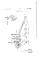
- Fig. l is a side elevation, partly in section'- and broken away, of a linotype keyboard mechanism equipped with the present improvements
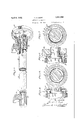
- Fig. 2 is a detail perspective view of the improved retaining cap, a portion thereof being cut away to show .thebevelled wall of its eccentric recess;
- Fig. 3 is an enlarged perspective View, showing the manner in which the rubber covered roll is mounted
- Fig. 4 is a detail sectional view, showing the cap with its eccentric recess disengaged from or in registry with the eccentric loc-king rib of the roll hub;
- Fig. 5 is a vertical section taken on the line 5-5 of Fig. 4;
- Fig. 6 is a section similar to Fig. 4, showing the cap with its eccentric recess in locking engagement with or out of registry with the eccentric rib of the roll hub; and Y Fig. 7 is a vertical section taken on the line 7-7 of Fig. 6.
- escapements (not shown), which are operated by a series of vertical reciprocating reeds A suitably guided in the framework and constantly urged downward by strong pull springs A1 (see Fig. l). rlhe upward movement of the reeds against the action of their springs is effected by horizontally disposed yokes B arranged in two banks or series and with their inner ends in position to engage the reeds.
- the yokes are formed with vertical open slots which fit over pivot rods B1; and between their ends, the yokes are provided with rotary cams or eccentrics C pivoted thereto and adapted to be rotated by the underlying power-driven rolls D1, there being two of these rolls, one for each series of yokes.
- the yokes B are supported upon pivoted trip dogs E, which hold the yokes at such height as to maintain the cams C out of engagement with the rolls D, the cams in this position ofthe parts being restrained against rotary7 motion by their engagement with fixed stop pins C1.
- Each of the rolls D1 is covered with a rubber tube or sleeve D for friotional contact with the rotary cams C and (as best shown in Fig. 3) is formed with reduced end bearing portions or hubs D2 and D2, the former being journaled in a fixed bearing block H1 at the left of the keyboard frame H, and the latter being journaled in a bearing sleeve or bushing D1 secured by means of a set screw h1 to a supporting block H2 at the right of the keyboard frame.
- the roll hub D3 is provided with a grooved collar D5 against which the end of the roll D1 abuts, while at the outer end of the sleeve, the roll hub (extended for the purpose) is provided with a driving gear D, which meshes with a similar gear D7 (Fig. l) secured to the other power-driven roll.
- the collar D5 being of slightly greater diameter than that of the roll D1, presents an annular shoulder for engagement with the right-hand end of the rubber coveringv tube D and thus prevents any endwise movement ofV the tube toward the right. It will be observed, however, (see Fig.
- the sleeve Dt is formed with the customary spot7 or recess wherein the set screw h1 engages and also with a radially disposed oil duct d1, which registers with an aperture h2 formed in the block H2 to permit lubrication of the bearing. It is necessary, therefore, to locate the sleeve in definite relation to the block H2, and the means usually employed for this purpose (see Fig. 3) consists of a stud or pin d2, which projects radially from the sleeve D4 and seats in an open notch ft2 formed in the right end of the block H2.
- the collar Dr formed with an annular groove d3 which is adapted to intercept and deflect any oil escaping from the bearing sleeve D1' or block H2 before it comes in contact with the rubber cover D.
- a knurled cap or nut J which may be quickly applied and locked to the roll or as quickly Vunlocked and detached from the roll when the latter is removed from the keyboard frame.
- the cap J (as best shown in Figs.
- the roll hub D2 is provided with a circular ec- -centrically located rib or collar D10, which may be integral with or otherwise permanently secured to the hub.
- the outer surface or periphery D9 of the ⁇ rib D10 (see Figs. 4 and 6) is beveled or cone-shaped in the direction of the end face DS, and the size of said rib is such that it will enter a circular recess J1 formed in the roll engaging face of the cap J when the latter is moved axially up against the end face D0 of the roll.
- the recess J1 is disposed eccentrically of the roll h ub D2 and presents s a correspondingly bevelled or cone-shaped bevelled surface D0 of the rib D10.
- the diameter of the recess J1 is only slightly greater than that of the rib D10, so that when tli-e latter enters the same as permitted by the registration o-f the two (see Figs. 4.- and 5), a slight turn of the cap relatively to the roll hub is sufficient to cause the cooperating bevelled surfaces D0 and J 5 to become frictionally engaged and interlocked (see Figs.
- cap J is locked securely to the power-driven roll D1-to hold its rubber cover D in place thereto, and,atthe same time, it is clamped tightly against the end face D8 of the roll to provide'an oiltight oint at this point and thus protect the rubber tube or cover D from any of they faces of the cap.
- a keyboard mechanism of the class described the combination of al power-driven roll for operating the cams, a rubber covering-tube removably mounted on the roll, means for preventing endwise movement of the rubber tube upon the roll in one direction. and a quick detachable cap also mounted on the roll for preventing endwise movement of the rubber tube in the opposite direction.
- a power-driven vroll for operating the calins a rubber covering-tube removably mounted on the roll, means for preventing endvvise movement of the rubber tube upon the roll in one direction, a cap detacliably mounted on one end of said roll for preventing endvvise movement the rubber tube upon the roll iii one direction, a capdetachably mounted on one end of said roll Vfor preventing endwise movement of the rubber tube in the opp site direction, and means adapted by a partial rotation of the cap in either direction tor loclring it iii its active position.
- keyboard Vmechanism of the class described the combination of a power-driven roll Jr ⁇ or operating the cams, a rubber covering-tube removably mounted on tlie roll, means for preventing endv-.fise movement of the rubber tube upon the roll in one direction, a retaining cap mounted on one end of the roll for preventing endivise movement of the rubber tube inthe opposite direction, said cap being removable from the roll in an axial direction, and an ⁇ eccentric member located permanently on the roll and adapted by a partial rotation of the cap in opposite directions to loci; the latter against arial move- ⁇ ment in its active position or to release it preparatory to removal.
- an eccentrically yrecessed cap for preventing endwise movement of the rubber tube in the opposite cirection, said cap being slidably ⁇ mounted for axial movement upon the bearing hub at one end of the roll, and means for locking the cap in its active position against axial movement, such means comprising an veccentric member formed on the roll hub and adapted to be engaged with the Walls ci the recess in the cap by a relative partial rotation of the cap and roll.l
- Aan eccentrically recessed cap for preventing endvvise movement of the rubber tube iii the opposite direction, said cap being slidably mounted for axial movement upon the bearing hub at one end of the roll, and means for locking the cap in its active position against axial movement, said means comprising an eccentric member formed on the roll hub and bevelled at its outer edge so as to engage with correspondingly bevelled inner Walls of the recess formed in the cap when the latter is given a partial turn in either direction.
- a power-driven roll for operating the cams
- a rubber covering-tube removably mounted on the roll
- a cap detachably mounted on the roll for preventing endwise movement ot the rubber tube in the opposite direction
- means for locking the cap in'its active position said cap being formed in its outer periphery with an annular groove to intercept the lubricating oil escaping from the roll bearings.
- a keyboard mechanism of the class described the combination of a power-driven roll for operating the cams, a rubber covering-tube removably mounted on the roll, means for preventing endWise movement of the rubber tube kupon the roll iii one direction, a cap detachably mounted on the roll for preventing endwise movement of the rubber tube in the opposite direction, and means adapted by a partial rotatio-n of the cap for locking it in its active position, said cap being formed in its outer periphery with a plurality of annular grooves for intercepting the lubricating oil escaping from the roll bearings.
- a keyboard mechanism oit the class described, the combination ot a power-driven roll for operating the cams, a rubber covering-tube removably mounted on the roll, means for preventing endwise movement oi the rubber tube upon the roll in one direction, an externally grooved cap detacliably mounted on the roll for preventing endvvise movement of the rubber tube in the opposite direction, and means adapted by a partial rotation of the cap for locking it in its active position, said locking means comprising an eccentric member formed on the roll and having its outer edge bevelled for engagement with a correspondingly bevelled-Wall recess formed in the roll engaging face ot the cap.
- a keyboard mechanism of the class described the combination ci a power-driven roll tor operating the cams, a rubber covering-tube removably mounted on the roll, said roll presenting a shoulder at one end flush with the rubber tube, a locking member formed on the roll and located immediately adjacent said end should-er, means 'for preventing endivise movement of tbe rubber tube upon the roll in one direction, and a quick detachable externally grooved cap for preventing endwise movement of the rubber tube in the opposite direction, said cap and locking member being formed with correspondingly bevelled surfaces adapted by their engagement through a partial rotation of the cap to lock the latter in its active position against the end shoulder of the roll.
- a power-driven cam operating roll formed at one end with a reduced end portion or bearing hub, a rubber covering-tube mounted on the roll and removable endwise 1 therefrom at that end, and a retaining cap for holding the rubber tube in place upon the roll, said cap being detachably mounted on thel roll and presenting an annular shoulder for engagement with the end of the rubber tube.
- a power-driven cam operating roll formed at one end with a reduced end portion or bearing hub, a rubber covering-tube mounted on the roll and removable endwise therefrom at that end, and a retaining cap for holding the rubber tube in place upon the roll, said cap being detachably mounted on the roll hub and presenting an annular shoulder for engagement with the end of the rubber tube.
- a power-driven cam operating roll formed at one end with a reduced end portion or bearing hub, a rubber covering- ""1' tube mounted on the roll and removable endwise therefrom at that end, a retaining cap centrally bored to lit loosely upon the roll hub and presenting an annular shoulder for engagement with the end of the rubber tube,
- a power-driven cam operating roll formed at one end with a reduced end portion or bearing hub, a rubber coveringtube mounted on the roll and removable endwise therefrom at that end, a retaining cap for holding the rubber tube in place upon the rol-l, said cap being centrally bored to fit loosely upon the roll hub and presenting a side face adapted to make Huid-tight contact with the end face of the roll proper, and means adapted by ak partial rotation of the cap with reference tothe roll hub to draw the side face of the cap tightly up against the end face of the roll.
- a power-driven cam operating roll formed at one end with a reduced end portion or bearing hub, a rubber covering-V tube mounted on the roll and removable endwise therefrom at that end, a retaining cap for holding the rubber tube in place upon the roll, said cap being centrally bored to fit portion or bearing hub, a rubber covering-v tube mounted on the roll and removable endwise therefrom at that end, a retaining cap for holding-the rubber tube in place upon the roll, said cap being centrally bored to it loosely upon the roll hub and presenting a side face adapted to make Huid-tight contact with the end face of the roll proper, a circu- ⁇ lar eccentrically located bevelled-wall recess formed in the roll contactingr face of the retaining cap, and a circular eccentrially located bevelled-edge rib or collar formed on the roll' hub immediately adjacent the roll end face and adapted to enter the cap recess, ythe bevelled surfaces of the rib and cap rece
Landscapes
- Rolls And Other Rotary Bodies (AREA)
Description
April 5, 1932 H. A. BURT 'g-g KEYBOARD MEGHANISM Filed Nov. 29, 1.929 2 Sheets-Sheet l INVENTOR K BY d AZTOR Y;
April 5, 1932. H. A. BURT 1,851,966
KEYBOARD MECHANI SM Filed Nov. 29, 1929 2 sheets-Sheet 2 l Which, When the keys are depressed, release- Patented Apr. 5, 1932 UNITED STATES PATENT OFFICE `:HAROLD A. BURT, F ST.,ALBANS, NEW YORK, ASSIGNOR TO MERGENTHALER LINO- TYPE COMPANY, A CORPORATION NEW YORK KEYBOARD MECHANISM Application tlledyNovember 29, 1929. Serial No. 410,292.
This invention relates to keyboard mechanisms such as are employed in the commercial linotype machines or as illustrated in the United States patent to P. T. DodgeNo. 530,931. Ordinarily, such mechanisms comprise two series of pivoted cam yokes adapted mally sustain the cams out of contact with a Y pair of underlying,power-driven rolls, but
the yokes and allow the cams to engage the rolls for rotation thereby. As the cams are thus rotated, they swing the pivoted yokes up- `wardly at their free ends and operate the in overlying escapement reeds, all in the manner well understood inthe art. c
Ordinarily, the power-driven rolls are each covered With rubber, thisv rubber covering being in the form of a long seamless tube or sleeve, which is slipped endwise onto the metal roll and held in place thereon. In actual practice, the life of such rubber covering tubes or sleeves is comparatively short on account of the Wear to which they are subf`= vjected by the repeated engagement therewith of the rotary cams, Which bear thereon with substantial pressure; in fact,oftentimes very decided grooves are cut into the lrubber tubes Abecause of this heavy pressure. As a result,
f' it becomes necessary from time to time to Vremove the Worn tubes from the rolls and sub stitute new ones, and this operation is slow and tedious, causing considerable inconvenience and loss of time.
The present invention is intended to ob-V viate the foregoing and other objections and aims to provide for the quick and ready removal and substitution of the rubber tubes, and this in a Way Which Will prevent the Y i 3 lubricating oil at the roll bearings from finding its Way onto the rubber tubes When thckeyboard is in operation,-a feature of importance because of the slippage Which would otherwise take placebetween the rubber covered rolls and the rotary cams whenv the latter are operated by the rolls. With these ends in view, the present invention contemplates improved means in the form of a cap or nut Which is of aslightly greater diameter than that of the power-driven roll, and Which may be quickly attached to and detached from the roll at one end thereof, the cap thus serving not only to restrain the rubber tube against endwise displacement on the roll, but also to protect it from oil that is likely to escape from the adjacent roll bearing. In the preferred embodiment illustrated, the cap is bored to tit over the hub of the metal roll and 'is formed at its inner side face With an eccentric bevelled-Wall recess to interlock With an eccentric bevelled-edge rib or collar formed upon the roll hub. c
According to this arrangement, the rub* ber tube maybe locked in place upon the I metal roll, after being slipped endvvise thereon, simply by applying the retaining cap to the rollhub and giving it (the cap)V a slight rotation in either direction to cause its eccentric recess to move out of registry with the eccentric rib formed on the roll hub, theV bevelled surfaces ofthese parts serving byk such rotation of the cap to draw it tightly up against the end of the roll proper` and provide a substantially duid-tight joint between' them so as thus to prevent the oil from seeping through onto the rubbery tube which covers the outer surface of the roll. Due to its llarger diameter, the cap will of course protrude beyond the outer surface of the metal roll and so will provide an annular shoulder to engage the rubber cover or tube and prevent it from creeping off the roll at` that end. A similar cap could, if desired, be placed at the opposite end of the roll to prevent the rubber tube from Working oif the roll at that end, but the retaining member now facewise off the roll hub and allow the rubber tube to be drawn endwise from the roll.
The eXact construction and operation of the parts will best be understood from the detailed description to follow, altho it will now be apparent from what has been said that the whole process of replacing a worn rubber tube by a new one can be carried out with the minimum of delay and effort.
Referring to the drawings Fig. l is a side elevation, partly in section'- and broken away, of a linotype keyboard mechanism equipped with the present improvements Fig. 2 is a detail perspective view of the improved retaining cap, a portion thereof being cut away to show .thebevelled wall of its eccentric recess;
Fig. 3 is an enlarged perspective View, showing the manner in which the rubber covered roll is mounted;
Fig. 4 is a detail sectional view, showing the cap with its eccentric recess disengaged from or in registry with the eccentric loc-king rib of the roll hub;
Fig. 5 is a vertical section taken on the line 5-5 of Fig. 4;
Fig. 6 is a section similar to Fig. 4, showing the cap with its eccentric recess in locking engagement with or out of registry with the eccentric rib of the roll hub; and Y Fig. 7 is a vertical section taken on the line 7-7 of Fig. 6.
As is usual in linotype machines, the release of the matrices from their storage magazine is controlled by escapements (not shown), which are operated by a series of vertical reciprocating reeds A suitably guided in the framework and constantly urged downward by strong pull springs A1 (see Fig. l). rlhe upward movement of the reeds against the action of their springs is effected by horizontally disposed yokes B arranged in two banks or series and with their inner ends in position to engage the reeds. At their opposite ends, the yokes are formed with vertical open slots which fit over pivot rods B1; and between their ends, the yokes are provided with rotary cams or eccentrics C pivoted thereto and adapted to be rotated by the underlying power-driven rolls D1, there being two of these rolls, one for each series of yokes. At their inner ends, the yokes B are supported upon pivoted trip dogs E, which hold the yokes at such height as to maintain the cams C out of engagement with the rolls D, the cams in this position ofthe parts being restrained against rotary7 motion by their engagement with fixed stop pins C1. When. however` theV dogs are moved, the cams C are disengaged from the stop pins C1 and, as the yokes drop, actuate the latter through their Contact with one or another ofthe rolls vD in the manner pre viously stated. The movement of the trip dogs is controlled by a series of vertical key bars F slidably arranged in the keyboard frame and connected directly to the linger keys or key levers Gr.
Each of the rolls D1 is covered with a rubber tube or sleeve D for friotional contact with the rotary cams C and (as best shown in Fig. 3) is formed with reduced end bearing portions or hubs D2 and D2, the former being journaled in a fixed bearing block H1 at the left of the keyboard frame H, and the latter being journaled in a bearing sleeve or bushing D1 secured by means of a set screw h1 to a supporting block H2 at the right of the keyboard frame. At the inner end of the sleeve D4, the roll hub D3 is provided with a grooved collar D5 against which the end of the roll D1 abuts, while at the outer end of the sleeve, the roll hub (extended for the purpose) is provided with a driving gear D, which meshes with a similar gear D7 (Fig. l) secured to the other power-driven roll. The collar D5, being of slightly greater diameter than that of the roll D1, presents an annular shoulder for engagement with the right-hand end of the rubber coveringv tube D and thus prevents any endwise movement ofV the tube toward the right. It will be observed, however, (see Fig. 3) that the diameter of the sleeve D", is slightly greater than l that of the collar D5 or the Vouter diameter of the rubber tube D, so that by loosening the set screw h1 the roll D1 and all parts carried thereby may be shifted axially (for removal or replacement) through the aperture which accommodates the sleeve D1 in the supporting block H2.
`The sleeve Dt is formed with the customary spot7 or recess wherein the set screw h1 engages and also with a radially disposed oil duct d1, which registers with an aperture h2 formed in the block H2 to permit lubrication of the bearing. It is necessary, therefore, to locate the sleeve in definite relation to the block H2, and the means usually employed for this purpose (see Fig. 3) consists of a stud or pin d2, which projects radially from the sleeve D4 and seats in an open notch ft2 formed in the right end of the block H2. This arrangement, while permitting the roll to bev quickly removed, insures the correct angular location of the bearing sleeve within its supporting block before the roll can be pushed home in its bearings. As shown clearly in Fig. 3, the collar Dris formed with an annular groove d3 which is adapted to intercept and deflect any oil escaping from the bearing sleeve D1' or block H2 before it comes in contact with the rubber cover D.
The parts, so far described, in construction and mode of operation. are substi'uitially the same as those embodied in the commercial linotype machine or as illustrated in the Dodge patent hereinbefore mentioned.
According to the present invention, in or` der to retain the rubber tube D in its proper position on the metal roll D1 against the collar D5 and thus prevent it fi'om creeping endwisel toward the left, there is provided a knurled cap or nut J, which may be quickly applied and locked to the roll or as quickly Vunlocked and detached from the roll when the latter is removed from the keyboard frame. The cap J (as best shown in Figs.
l and 6) is formed with a central bore J'i to it loosely on the roll hub D2 and normally occupies a position between the inner end of the bea-ring block H1 and the adjacent end face DS of the roll. The outer edge or periphery of the cap, however, overlaps or protrudes beyond the outer surface ofthe roll D1 so as 'to engage the rubber tube D which as clearly shown in Figs. 4t and 6 terminates flush with the end face DS.
Immediately adjacent the end face D8, the roll hub D2 is provided with a circular ec- -centrically located rib or collar D10, which may be integral with or otherwise permanently secured to the hub. The outer surface or periphery D9 of the` rib D10 (see Figs. 4 and 6) is beveled or cone-shaped in the direction of the end face DS, and the size of said rib is such that it will enter a circular recess J1 formed in the roll engaging face of the cap J when the latter is moved axially up against the end face D0 of the roll.
The recess J1, like the rib D10, is disposed eccentrically of the roll h ub D2 and presents s a correspondingly bevelled or cone-shaped bevelled surface D0 of the rib D10. The diameter of the recess J1 is only slightly greater than that of the rib D10, so that when tli-e latter enters the same as permitted by the registration o-f the two (see Figs. 4.- and 5), a slight turn of the cap relatively to the roll hub is sufficient to cause the cooperating bevelled surfaces D0 and J 5 to become frictionally engaged and interlocked (see Figs.
6 and 7 In this way, the cap J is locked securely to the power-driven roll D1-to hold its rubber cover D in place thereto, and,atthe same time, it is clamped tightly against the end face D8 of the roll to provide'an oiltight oint at this point and thus protect the rubber tube or cover D from any of they faces of the cap.
It will now be seen-that, when it is desired to replace a worn or mutilated rubber tube D from the power-driven roll D1, the 'whole roll ensemble, after first loosening the set screw h1, is removed endwise through Vthc supporting block H2 at the right in the inanfacewise up against the'end shoulder D8 of the roll, whereupon by a partial turn in either direction the cap will be relocked to the roll in its cover retaining and oil protecting position, and theroll ensemble thus made ready for restoration through the supporting blockv D3 to the keyboard frame.
Vhen the keyboard is in use, the powerdriven rolls `will be rotated continuously, and it will be understood that the retaining cap J will be rotated therewith, suiiicient clearance being allowed between the cap and the adjacent bearing H1 to permit such rota-V tion to take place freely. If however, the cap should be accidentally turned to bring its eccentric recess J1 in register with the eccentric rib D10, the bearing H1 will prevent the cap from moving axially far enough to disturb the engaging relation of the bevelled surfaces J 5 and D0. Hence the continued rotation of the parts will almost instantly effect the reengagement of the bevelled surfaces, which will then draw the cap away from the bearing H1 and clamp it tightly up against the end face D8 of the roll.
In the accompanying drawings, the invention is shown merely in preferred form and by way of example, but, obviously, many changes and variations may be made therein and in its mode of application, which will still be comprised within its spirit. It should, therefore, be understood that the invention is not Having thus described my invention, what Y I claim is:
1. In a keyboard mechanism of the class described, the combination of al power-driven roll for operating the cams, a rubber covering-tube removably mounted on the roll, means for preventing endwise movement of the rubber tube upon the roll in one direction. and a quick detachable cap also mounted on the roll for preventing endwise movement of the rubber tube in the opposite direction.
2. In a keyboard mechanism of the class described, the combination of a power-driven roll for operating the cams, a rubber covering-tube removably mounted on the roll,
means forpreventing endwise movement of the rubber tube upon theroll in one direction, retaining cap slidably mounted onone end of the roll for preventing endwise movement kkof the rubber tube inthe opposite direction,
and releasable means for locking the cap against axial movement in its active position. 3. In a keyboard mechanism of the class described, the combination of a power-driven vroll for operating the calins, a rubber covering-tube removably mounted on the roll, means for preventing endvvise movement of the rubber tube upon the roll in one direction, a cap detacliably mounted on one end of said roll for preventing endvvise movement the rubber tube upon the roll iii one direction, a capdetachably mounted on one end of said roll Vfor preventing endwise movement of the rubber tube in the opp site direction, and means adapted by a partial rotation of the cap in either direction tor loclring it iii its active position.
5. In keyboard Vmechanism of the class described, the combination of a power-driven roll Jr`or operating the cams, a rubber covering-tube removably mounted on tlie roll, means for preventing endv-.fise movement of the rubber tube upon the roll in one direction, a retaining cap mounted on one end of the roll for preventing endivise movement of the rubber tube inthe opposite direction, said cap being removable from the roll in an axial direction, and an `eccentric member located permanently on the roll and adapted by a partial rotation of the cap in opposite directions to loci; the latter against arial move- ^ment in its active position or to release it preparatory to removal.
6. YIn a keyboard mechanism'o the class described, the combination ot a power-driven vroll for operating the cams, a rubber covering-tube removably mounted on the roll,
means for preventing eiidiviseriiiovement of the rubber tube upon the roll in one direction, an eccentrically yrecessed cap for preventing endwise movement of the rubber tube in the opposite cirection, said cap being slidably` mounted for axial movement upon the bearing hub at one end of the roll, and means for locking the cap in its active position against axial movement, such means comprising an veccentric member formed on the roll hub and adapted to be engaged with the Walls ci the recess in the cap by a relative partial rotation of the cap and roll.l
7. In a keyboard mechanism of the class described, the combination of a power-driven roll for operating the cams, a rubber covering-tube remove ly mounted on the roll, means ior preventing endvvise movement of the rubber tube upon the rollin one direction,
Aan eccentrically recessed cap for preventing endvvise movement of the rubber tube iii the opposite direction, said cap being slidably mounted for axial movement upon the bearing hub at one end of the roll, and means for locking the cap in its active position against axial movement, said means comprising an eccentric member formed on the roll hub and bevelled at its outer edge so as to engage with correspondingly bevelled inner Walls of the recess formed in the cap when the latter is given a partial turn in either direction.
8. In a keyboard mechanism of the class described, the combination oi a power-driven roll for operating the cams, a rubber covering-tube removably mounted on the roll, means for preventing endWise movement of the rubber tube upon the roll in one direction, a cap detachably mounted on the roll for preventing endwise movement ot the rubber tube in the opposite direction, and means for locking the cap in'its active position, said cap being formed in its outer periphery with an annular groove to intercept the lubricating oil escaping from the roll bearings.
9. In a keyboard mechanism of the class described, the combination of a power-driven roll for operating the cams, a rubber covering-tube removably mounted on the roll, means for preventing endWise movement of the rubber tube kupon the roll iii one direction, a cap detachably mounted on the roll for preventing endwise movement of the rubber tube in the opposite direction, and means adapted by a partial rotatio-n of the cap for locking it in its active position, said cap being formed in its outer periphery with a plurality of annular grooves for intercepting the lubricating oil escaping from the roll bearings.
l0. In a keyboard mechanism oit the class described, the combination ot a power-driven roll for operating the cams, a rubber covering-tube removably mounted on the roll, means for preventing endwise movement oi the rubber tube upon the roll in one direction, an externally grooved cap detacliably mounted on the roll for preventing endvvise movement of the rubber tube in the opposite direction, and means adapted by a partial rotation of the cap for locking it in its active position, said locking means comprising an eccentric member formed on the roll and having its outer edge bevelled for engagement with a correspondingly bevelled-Wall recess formed in the roll engaging face ot the cap.
11. In a keyboard mechanism of the class described, the combination ci a power-driven roll tor operating the cams, a rubber covering-tube removably mounted on the roll, said roll presenting a shoulder at one end flush with the rubber tube, a locking member formed on the roll and located immediately adjacent said end should-er, means 'for preventing endivise movement of tbe rubber tube upon the roll in one direction, and a quick detachable externally grooved cap for preventing endwise movement of the rubber tube in the opposite direction, said cap and locking member being formed with correspondingly bevelled surfaces adapted by their engagement through a partial rotation of the cap to lock the latter in its active position against the end shoulder of the roll.
12. In or for a keyboard mechanism of the class described, a power-driven cam operating roll formed at one end with a reduced end portion or bearing hub, a rubber covering-tube mounted on the roll and removable endwise 1 therefrom at that end, and a retaining cap for holding the rubber tube in place upon the roll, said cap being detachably mounted on thel roll and presenting an annular shoulder for engagement with the end of the rubber tube.
13. In or for a keyboard mechanism of the class described, a power-driven cam operating roll formed at one end with a reduced end portion or bearing hub, a rubber covering-tube mounted on the roll and removable endwise therefrom at that end, and a retaining cap for holding the rubber tube in place upon the roll, said cap being detachably mounted on the roll hub and presenting an annular shoulder for engagement with the end of the rubber tube.
14. In or for a keyboard mechanism of the class described, a power-driven cam operating roll formed at one end with a reduced end portion or bearing hub, a rubber covering- ""1' tube mounted on the roll and removable endwise therefrom at that end, a retaining cap centrally bored to lit loosely upon the roll hub and presenting an annular shoulder for engagement with the end of the rubber tube,
; and releasable means adapted by a partial rotation of the cap for locking it in its tube retaining position.
15. A keyboard roll arrangement as in claim 14, characterized kby the fact that the retaining cap therein referred to is formed with an eccentrically located recess, and that the roll hub is provided with an eccentrically located rib to enter said recess and be frictionally engaged therewith by a partial rotation of the cap.
16. In or for a keyboard mechanism of the class described, a power-driven cam operating roll formed at one end with a reduced end portion or bearing hub, a rubber coveringtube mounted on the roll and removable endwise therefrom at that end, a retaining cap for holding the rubber tube in place upon the rol-l, said cap being centrally bored to fit loosely upon the roll hub and presenting a side face adapted to make Huid-tight contact with the end face of the roll proper, and means adapted by ak partial rotation of the cap with reference tothe roll hub to draw the side face of the cap tightly up against the end face of the roll.
17. In or for a keyboard mechanism of the class described, a power-driven cam operating roll formed at one end with a reduced end portion or bearing hub, a rubber covering-V tube mounted on the roll and removable endwise therefrom at that end, a retaining cap for holding the rubber tube in place upon the roll, said cap being centrally bored to fit portion or bearing hub, a rubber covering-v tube mounted on the roll and removable endwise therefrom at that end, a retaining cap for holding-the rubber tube in place upon the roll, said cap being centrally bored to it loosely upon the roll hub and presenting a side face adapted to make Huid-tight contact with the end face of the roll proper, a circu-` lar eccentrically located bevelled-wall recess formed in the roll contactingr face of the retaining cap, and a circular eccentrially located bevelled-edge rib or collar formed on the roll' hub immediately adjacent the roll end face and adapted to enter the cap recess, ythe bevelled surfaces of the rib and cap recess being adapted to be engaged and disengaged by a partial rotation of the cap upon the rollhub, substantially as and for the purpose described.
In testimony whereof, this specification has been duly signed by:
HAROLD A. BURT.
Priority Applications (1)
| Application Number | Priority Date | Filing Date | Title |
|---|---|---|---|
| US410292A US1851966A (en) | 1929-11-29 | 1929-11-29 | Keyboard mechanism |
Applications Claiming Priority (1)
| Application Number | Priority Date | Filing Date | Title |
|---|---|---|---|
| US410292A US1851966A (en) | 1929-11-29 | 1929-11-29 | Keyboard mechanism |
Publications (1)
| Publication Number | Publication Date |
|---|---|
| US1851966A true US1851966A (en) | 1932-04-05 |
Family
ID=23624089
Family Applications (1)
| Application Number | Title | Priority Date | Filing Date |
|---|---|---|---|
| US410292A Expired - Lifetime US1851966A (en) | 1929-11-29 | 1929-11-29 | Keyboard mechanism |
Country Status (1)
| Country | Link |
|---|---|
| US (1) | US1851966A (en) |
-
1929
- 1929-11-29 US US410292A patent/US1851966A/en not_active Expired - Lifetime
Similar Documents
| Publication | Publication Date | Title |
|---|---|---|
| US1816948A (en) | Lock-up for rolls | |
| US1851966A (en) | Keyboard mechanism | |
| US2047364A (en) | Plate cylinder for printing presses and stereotype plates | |
| US2748699A (en) | Block-carrying devices for sheet or web fed rotary printing machines | |
| US2329830A (en) | Rotary printing press | |
| US3000301A (en) | Impression cylinders | |
| US2047732A (en) | Brake beam strut bushing | |
| US1558108A (en) | Qijardt | |
| US1530871A (en) | Printing apparatus | |
| US400269A (en) | Charles a | |
| US1094065A (en) | Duplicating-machine. | |
| US1887382A (en) | Duplicating machine | |
| US1887625A (en) | Roller for line slug machines | |
| US1930807A (en) | Printing device | |
| US2106078A (en) | Plate holder for intaglio printing machines | |
| US1963585A (en) | Lead for printing presses | |
| US1900664A (en) | Printing press | |
| US1971081A (en) | Inking mechanism for printing machines | |
| US1985628A (en) | Plate holding means for printing presses | |
| US2166631A (en) | Printing press inking mechanism | |
| US860637A (en) | Fudge-box. | |
| US508801A (en) | Shaft for winding paper | |
| US1768994A (en) | Drill-steel centralizer | |
| US427320A (en) | Means for securing flexible printing-plates | |
| US1662232A (en) | Printing-plate holding means |