US1851963A - Coasting device - Google Patents
Coasting device Download PDFInfo
- Publication number
- US1851963A US1851963A US526457A US52645731A US1851963A US 1851963 A US1851963 A US 1851963A US 526457 A US526457 A US 526457A US 52645731 A US52645731 A US 52645731A US 1851963 A US1851963 A US 1851963A
- Authority
- US
- United States
- Prior art keywords
- rod
- recess
- runner
- rudder
- rear end
- Prior art date
- Legal status (The legal status is an assumption and is not a legal conclusion. Google has not performed a legal analysis and makes no representation as to the accuracy of the status listed.)
- Expired - Lifetime
Links
Images
Classifications
-
- B—PERFORMING OPERATIONS; TRANSPORTING
- B62—LAND VEHICLES FOR TRAVELLING OTHERWISE THAN ON RAILS
- B62B—HAND-PROPELLED VEHICLES, e.g. HAND CARTS OR PERAMBULATORS; SLEDGES
- B62B17/00—Accessories or details of sledges
- B62B17/06—Superstructures; Attachments therefor
- B62B17/063—Seats or other supports specially adapted for the user
- B62B17/065—Seats or other supports specially adapted for the user the user being standing up
-
- A—HUMAN NECESSITIES
- A63—SPORTS; GAMES; AMUSEMENTS
- A63C—SKATES; SKIS; ROLLER SKATES; DESIGN OR LAYOUT OF COURTS, RINKS OR THE LIKE
- A63C5/00—Skis or snowboards
- A63C5/06—Skis or snowboards with special devices thereon, e.g. steering devices
-
- B—PERFORMING OPERATIONS; TRANSPORTING
- B62—LAND VEHICLES FOR TRAVELLING OTHERWISE THAN ON RAILS
- B62B—HAND-PROPELLED VEHICLES, e.g. HAND CARTS OR PERAMBULATORS; SLEDGES
- B62B13/00—Sledges with runners
- B62B13/02—Sledges with runners characterised by arrangement of runners
- B62B13/04—Sledges with runners characterised by arrangement of runners arranged in a single line
- B62B13/043—Sledges with runners characterised by arrangement of runners arranged in a single line having one single runner
Definitions
- the prime object of the invention resides in the provison of a device of this nature with means whereby the same may be efli- 7 ciently and efliectively steered while in use so that the user nay naintain a desired course in an expeditious manner.
- Another very important object of the ,invention resides in the provision of a device of this nature which is simple in its Construction, inexpensive to manufacture, strong and durable, thoroughly efiicient and reliable in use and operation, and otherwise well adapted to the purpose for which it is designed.
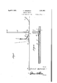
- FIG. 1 is a side elevation of the device embodying the features of my invention
- Figure 2 is a top plan view thereof
- Figure 3 is a fragmentary top plan view thereof with the top board removed
- Fgure 4 is a detail sectional View taken substantially on the line 4-4 of F igure 2.
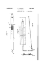
- Figure 5 is a View of the rod and the rudder on the rear end thereof.
- the numeral 5 denotes an elongated flat like runner, the forward end of which is curved upwardly as at 6 and also tapers upwardly as is illustrated in Figure 2. From a forward intermediate portion there extends rearwardly a recess 7 formed in the upper surface of the runner and this recess extends to the rear end thereof.
- a shaft 8 is journalled n a hearing 9 in'the bottom of the forward end of the recess and rises vertically through a plate 10 across the forward* end of the reeess being also journalled therethrough and a tubular handle 11 is fixed over the sha'ft and has a cross head 12 'at the top thereof to pro- 1 vide hand grips.
- a suitable plate 14 is fixed in the upper porton of the recess to close the same.
- An elongated rod 15 has its forward end fixed on a. squared portion of the shaft 8 and extends rearwardly through the recess terminating in the rear of the rear end of' the runner in a rudder 16 which is flat like disposedin a vertical plane. It will readily be seen that by turning the handle, this rudder may be swung from side to side therebysteering the runner when the same is moving over the top of the Snow surface orthe like.
- a rubber pad 17 or the like is placed on top of the runner to the rear of the plate 10 so that the foot may be rested thereon and suitable strap means 18 may be utilized forholding the foot in place thereon.
- a body having a recess therein, a rod mounted in the recess, means for rockably mounting the forward end of the rod so that the rear end of the rod may swing across the recess said rod terminating rearwardly of 10 the body and having a rudder on the rear end i thereoi? and means forswinging the rod to shift the rudder from side to side With respect to the body .for steering the same.
- an elongated runner having a recess in the upper surface thereof extending from 'an intermediate point to'the rear end thereof, a rod in the recess terminating to the rear of the runner, means engaged with the forward end of the rod and rising above the runner for swinging the rod, and a rudder on the rear end of the rod.
- an elongated runner having a recess 25 in the upper surface thereof eXtending from an intermediate point to the rear end thereof, a rodein the recess terminating to the rear of therunner, means engaged With the forward end of the rod and rising above the ⁇ runner for' swinging the rod, and a rudder on the rear end of the rod, said rudder being of flat like-formation disposed in a vertical plane.
Landscapes
- Engineering & Computer Science (AREA)
- Chemical & Material Sciences (AREA)
- Combustion & Propulsion (AREA)
- Transportation (AREA)
- Mechanical Engineering (AREA)
- Toys (AREA)
Description
April 5, 1932. c ANDERSQN 1,851,963
COASTING'DEVICE Filed March 30, 1931 2 Sheets-Sheet l Byi ww A ltomey April 5, ANDERSON COASTING DEVICE Filed March 30, l93l 2 Sheets-Sheet 2 A lomcy Patented Apr. 5,' 1932 UNITED STATES P'ATENT OFFICE CHRIST ANDERSON, OF ONTONAGON, MICHIGAN, ASSIGNOR OFONE-HALF TO ELMER H.
WEBBER AND CARLO. BAY, OF ONTONAGON', MICHIGAN i COASTING DEVICE Application filed March 30, 1931." Serial No. 526,*157.
' to various coasting devices.
The prime object of the invention resides in the provison of a device of this nature with means whereby the same may be efli- 7 ciently and efliectively steered while in use so that the user nay naintain a desired course in an expeditious manner.
Another very important object of the ,invention resides in the provision of a device of this nature which is simple in its Construction, inexpensive to manufacture, strong and durable, thoroughly efiicient and reliable in use and operation, and otherwise well adapted to the purpose for which it is designed.
With the above and numerous other objects in View as will appear as the description pro ceeds, the invention resides in certain novel features of Construction, and in the combination and arrangement 'of parts as will be hereinafter more fully described and claimed.
In the drawings:
Figure 1 is a side elevation of the device embodying the features of my invention,
Figure 2 is a top plan view thereof,
Figure 3 is a fragmentary top plan view thereof with the top board removed,
Fgure 4 is a detail sectional View taken substantially on the line 4-4 of F igure 2.
Figure 5 is a View of the rod and the rudder on the rear end thereof.
Referring to the drawings, in detail it will be seen that the numeral 5 denotes an elongated flat like runner, the forward end of which is curved upwardly as at 6 and also tapers upwardly as is illustrated in Figure 2. From a forward intermediate portion there extends rearwardly a recess 7 formed in the upper surface of the runner and this recess extends to the rear end thereof.
'ljhe recess tapers forwardly as is clearly ndcated in Figure 3. A shaft 8 is journalled n a hearing 9 in'the bottom of the forward end of the recess and rises vertically through a plate 10 across the forward* end of the reeess being also journalled therethrough and a tubular handle 11 is fixed over the sha'ft and has a cross head 12 'at the top thereof to pro- 1 vide hand grips. v
A suitable plate 14: is fixed in the upper porton of the recess to close the same. An elongated rod 15 has its forward end fixed on a. squared portion of the shaft 8 and extends rearwardly through the recess terminating in the rear of the rear end of' the runner in a rudder 16 which is flat like disposedin a vertical plane. It will readily be seen that by turning the handle, this rudder may be swung from side to side therebysteering the runner when the same is moving over the top of the Snow surface orthe like.
A rubber pad 17 or the like is placed on top of the runner to the rear of the plate 10 so that the foot may be rested thereon and suitable strap means 18 may be utilized forholding the foot in place thereon.
It is thought that the Construction, operation, utility and advantages of this inventon will now be quite apparent to those skilled in this art without a more detailed description thereof.
The present` embodiment of theinvention has been disclosed in considerable detail merely for the purposes of exemplification since in actual practice it attains the features of advantage enumerated as desirable in the statement of theinvention and the above description.
It will be apparent that changes in the details of construction, and in the combination and arrangement of parts may be resorted to without departing from the spirit or scope of the invention as hereinafter claimed or may swing across the body, saidrod terminating rearwardly of the body and having a rudder on the rear end thereof.
2. In a coasting deviee of the class de- 5 scribed, a body having a recess therein, a rod mounted in the recess, means for rockably mounting the forward end of the rod so that the rear end of the rod may swing across the recess said rod terminating rearwardly of 10 the body and having a rudder on the rear end i thereoi? and means forswinging the rod to shift the rudder from side to side With respect to the body .for steering the same.
3. In a coasting devce of the class described, an elongated runner having a recess in the upper surface thereof extending from 'an intermediate point to'the rear end thereof, a rod in the recess terminating to the rear of the runner, means engaged with the forward end of the rod and rising above the runner for swinging the rod, anda rudder on the rear end of the rod.
4. In a eoasting device of the class described, an elongated runner having a recess 25 in the upper surface thereof eXtending from an intermediate point to the rear end thereof, a rodein the recess terminating to the rear of therunner, means engaged With the forward end of the rod and rising above the `runner for' swinging the rod, and a rudder on the rear end of the rod, said rudder being of flat like-formation disposed in a vertical plane. In testimony whereof I aflix my signature.
CHRIST ANDERSON.
Priority Applications (1)
| Application Number | Priority Date | Filing Date | Title |
|---|---|---|---|
| US526457A US1851963A (en) | 1931-03-30 | 1931-03-30 | Coasting device |
Applications Claiming Priority (1)
| Application Number | Priority Date | Filing Date | Title |
|---|---|---|---|
| US526457A US1851963A (en) | 1931-03-30 | 1931-03-30 | Coasting device |
Publications (1)
| Publication Number | Publication Date |
|---|---|
| US1851963A true US1851963A (en) | 1932-04-05 |
Family
ID=24097432
Family Applications (1)
| Application Number | Title | Priority Date | Filing Date |
|---|---|---|---|
| US526457A Expired - Lifetime US1851963A (en) | 1931-03-30 | 1931-03-30 | Coasting device |
Country Status (1)
| Country | Link |
|---|---|
| US (1) | US1851963A (en) |
Cited By (3)
| Publication number | Priority date | Publication date | Assignee | Title |
|---|---|---|---|---|
| US4162088A (en) * | 1978-03-20 | 1979-07-24 | Best | Powered snow ski |
| US4773659A (en) * | 1987-10-05 | 1988-09-27 | Rygiel Witold W | Articulated ski |
| DE4101550A1 (en) * | 1991-01-21 | 1992-07-23 | Trumpler Theodor Dipl Kaufm | Snow-board or monoski with steering column - has pref. forwardly inclined column fixed on base plate |
-
1931
- 1931-03-30 US US526457A patent/US1851963A/en not_active Expired - Lifetime
Cited By (3)
| Publication number | Priority date | Publication date | Assignee | Title |
|---|---|---|---|---|
| US4162088A (en) * | 1978-03-20 | 1979-07-24 | Best | Powered snow ski |
| US4773659A (en) * | 1987-10-05 | 1988-09-27 | Rygiel Witold W | Articulated ski |
| DE4101550A1 (en) * | 1991-01-21 | 1992-07-23 | Trumpler Theodor Dipl Kaufm | Snow-board or monoski with steering column - has pref. forwardly inclined column fixed on base plate |
Similar Documents
| Publication | Publication Date | Title |
|---|---|---|
| US2894760A (en) | Scooter sled with adjustable handle bars | |
| US3711109A (en) | Steering ski for snowmobiles and the like | |
| US2382150A (en) | Water ski | |
| US2216497A (en) | Toy | |
| US2893021A (en) | Water ski pole | |
| US2181391A (en) | Sled | |
| US1851963A (en) | Coasting device | |
| US1330644A (en) | Convertible coaster | |
| US2286350A (en) | Aquatic device | |
| US2735115A (en) | Toboggan | |
| US3103673A (en) | Water ski attachment | |
| US3269742A (en) | Convertible ski | |
| US2101229A (en) | Ice or snow scooter | |
| US3123373A (en) | Flexible ski-sled | |
| US2367765A (en) | Marine propulsion device | |
| US2967503A (en) | Lift device attachment for motorboats | |
| US3040697A (en) | Inboard mounted outboard motor watercraft | |
| US1691188A (en) | Propelled bathing device | |
| US3143996A (en) | Watercraft | |
| US2738525A (en) | Auxiliary support for water skiers | |
| US3150880A (en) | Snow sled | |
| US2247182A (en) | Snow scooter | |
| US1865985A (en) | Surf board attachment | |
| US2266842A (en) | Sled | |
| US1938701A (en) | Amusement device |