US1851943A - Hinged shank coupler - Google Patents
Hinged shank coupler Download PDFInfo
- Publication number
- US1851943A US1851943A US251360A US25136028A US1851943A US 1851943 A US1851943 A US 1851943A US 251360 A US251360 A US 251360A US 25136028 A US25136028 A US 25136028A US 1851943 A US1851943 A US 1851943A
- Authority
- US
- United States
- Prior art keywords
- coupler
- spreader
- shank
- arcuate
- car
- Prior art date
- Legal status (The legal status is an assumption and is not a legal conclusion. Google has not performed a legal analysis and makes no representation as to the accuracy of the status listed.)
- Expired - Lifetime
Links
- 239000000945 filler Substances 0.000 description 20
- 230000006835 compression Effects 0.000 description 7
- 238000007906 compression Methods 0.000 description 7
- 230000007480 spreading Effects 0.000 description 4
- 101000703464 Homo sapiens SH3 and multiple ankyrin repeat domains protein 2 Proteins 0.000 description 2
- 102100030680 SH3 and multiple ankyrin repeat domains protein 2 Human genes 0.000 description 2
- 238000010276 construction Methods 0.000 description 2
- 238000005360 mashing Methods 0.000 description 2
- 230000002441 reversible effect Effects 0.000 description 2
- 230000035939 shock Effects 0.000 description 2
- 125000006850 spacer group Chemical group 0.000 description 2
- 235000010627 Phaseolus vulgaris Nutrition 0.000 description 1
- 244000046052 Phaseolus vulgaris Species 0.000 description 1
- 239000006096 absorbing agent Substances 0.000 description 1
- 238000005266 casting Methods 0.000 description 1
- 230000003247 decreasing effect Effects 0.000 description 1
- 230000007547 defect Effects 0.000 description 1
- 230000006872 improvement Effects 0.000 description 1
- 239000000463 material Substances 0.000 description 1
- 230000007246 mechanism Effects 0.000 description 1
- 239000002184 metal Substances 0.000 description 1
- 230000004048 modification Effects 0.000 description 1
- 238000012986 modification Methods 0.000 description 1
Images
Classifications
-
- B—PERFORMING OPERATIONS; TRANSPORTING
- B61—RAILWAYS
- B61G—COUPLINGS; DRAUGHT AND BUFFING APPLIANCES
- B61G9/00—Draw-gear
- B61G9/20—Details; Accessories
- B61G9/24—Linkages between draw-bar and framework
Definitions
- the device relates to attachments of a car coupler to the draft gear or shock absorber of a railway car and comprises a coupler hav- V ing a shank consisting of two pieces pivoted the life of the coupler by decreasing the wear and mashing of the rear end of the shank where it engages the draft gear follower or casing.
- Another object of the invention is to 1ncrease the life of the coupler by increasing the bearing area between the draft key and the coupler.
- Another object of the invention 1s to provide means so that the car coupler will have a surface contact with the draft gear casing (or follower) in any lateral vposition it may assume in service.
- Another object of the invention 1s to provide means so that the car couplerwill have f a surface contact with ⁇ the front draft key in any lateral position it may assume in service.
- Another object ofthe invention is -to provide a spreader connected to the coupler shank so as to provide arcuate buiiing (compression) and pulling (tension) surfaces therebetween.
- Another object is to provide an arrangement for locking the spreader to the coupler and forming them so they can be assembled only by certain movements, which movements they can not make while in assembled position with associated parts of the car.
- Another object is to attach the spreader to the coupler without any n hinge or fulcrum pin, and in fact without any split key, cotter,
- Another object is to provide a spreader which is reversible andcannot'vbe improperlyvapplied to the coupler.
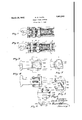
- Fig. 1 shows the coupler, spreader, draft gear and associated parts of the car when the draft gear is in compressed position and the coupler head is swung laterally.
- Fig. 2 is similar to Fig. 1 but shows the coupler pulled outwardly.
- Fig. 3 shows the relation of the coupler shank and the spreader in normal position.
- Fig. 4 is a side elevation of Fig. 3.
- f Fig'. 5 shows the spreader partially assembled With the coupler shank. f
- FIG. 6 is a perspective view of the rear end of the coupler shank.
- Fig. v7 is a perspective view of the spreader.
- Fig. 8 is a perspective view of the filler block.
- coupler head 1 coupler shank 2; draft gear 3; draft sill 4; front draft key 5; rear draft key 6; yoke 7 striking casting 8 and rear draft gear stop 9.
- the buff on the coupler is transmitted to the draft gear casing 10 (or follower) by the coupler shank 2 and the pulling force on the coupler is transmitted to the draft gear through the vdraft keys and yoke.
- the coupler is provided with oppositely projecting vertically disposed pintles upon which a filler or wearing piece 21 is pivoted.
- This block is preferably made of softer material than either the coupler or the spreader so that the friction of the moving parts will wear it instead of the spreader, Vwhich block is easily removed and replaced.
- the coupler has curved or arcuate rear ends 24 concentric with the pivot or pintle 20 which form bufling surfaces.
- the coupler is also provided with a rib 40 having buffing surfaces 25 concentric with the pivots 20 which are positioned in front of the pivot so that the pivot. is between the two arcuate bufling surfaces 24 and 25.
- the spreader has spaced apart horizontal flanges -31 connected by a main vwall' 32 having a flat bearing surface 33 for engagement with the draft gear casing or follower and each flange is provided with a ve-rtically disposed rib 3e@ having an arcuate front surface 35' for sliding engagement with the arcuate surface 25 on rib l0v of the coupler.
- Arcuate faces 37 are provided on the front of the spreader wal-l which slidably engage the arcuate rear end 24 or ends) of the coupler.
- the filler 21 h asy an aperture 26I for engagementwith the'pintle 202 and is of rectangular shape and in fact is preferably squarey to eliminate the possibility of improper application.
- the front part 22' of the filler is a pulling sur-face andengages the surface V36 of the rib 34 on the spreader and prevents the filler 2l from rotating around the pintle 20; i. e., retains the filler in operative position.
- the rear surface 23 of the filler is a buiing surface and engages the straight portions 39 on the front of the wall 32 of the spreader.
- a straight bearing surface 38 isV provided on the front wall o-f the spreader for engagement with the front draft key 5.
- This bean' ing' surface is made longer than the width of the coupler shank and in fact is made as longl as is permitted by the space between r the armsV of the yoke (see Fig. 3) so as to reduce the wear on the key and eliminate the elongation of the keyway.
- the compression or buff exerted on the coupler is transmitted bythe pivots 2() to the bntiingsurface 23: on the fillers 21 and the arcuate birding ⁇ surface 24, on the rearv endo-.f the coupler to the arcuate surfaces 37 on the wall of the L spreader and thence to the draft gear casingi 1O Part ⁇ ofthe compression is transmitted to the ribs 34 of the spreader by the arcuate rib lo on the coupler.
- the spreader is made wider than the coupler shank, in fact, is made as wide as possible between the portions of the yoke so as to furnish a large bea-ring areabetween it and thel draft gear casing.
- the pulling force exerted on thev coupler is transmitted to the spreader through pin- Y ties-20 and they pulling surface 22 on the Fillers and thence to the draft gear through they fronty draft key and the yoke.
- the spreader is also provided with a spacer 52 projecting into the slot 53: sothat when the coupler is under compression, this spacer prevents the spaced apart portions 54-*55 of the bifurcated coupler from coming together, and furthermore the flanges 30-31 of the spreader prevent the portions of thev split coupler from spreading apart.
- the flanges of the spreader may be provided with lateral lips 4l which underlie the projections 42 to prevent the flanges from spreading apart which they may have a tendency todo when the coupler isundercompression. This arrangement also prevents the bifurcated portions of the coupler and the anges of the spreader from spreading apart when the coupler is under tension. Besides its other functions, therefore, the spreader prevents distortion of the bifurcated coupler shank'.
- the spreader is assembled with the coupler ,byI engaging the fillers with the pintles and inserting the coupler shank in the'spreaderv until the pivot point of the concentric arcuate surfaces on the pintle coincides with the pivot point: of the arcuate surfaces on the spreader and then rotating orV swinging the spreader substantially ninety degrees.
- the parts ⁇ are assembled (see Fig. 3) and the yoke 7 and key 5- are in place it is impossible for the spreader to ⁇ become disengaged from the coupler or even to become cocked or assume a binding position. vWhile the parts are in operative position it is impossible for the fillers to be accidentally or intentionally removed.
- the spreader is made symmetrical 'about its middle horizontal plane so that it may be applied either way; or in other words, is reversible and furthermore is foolproof in that it can not be improperly applied.
- draft gear casing to indicate the box or housing which usually encases the shock absorbing mechanism.
- the projection 57 maintains the proper relation between the coupler and draft gear.
- a car coupler provided with oppositely projecting pintles and with its rear end arcuated to form a curved buiiing surface concentric with said pintles, a filler pivotally surrounding each pintle having a straight rear bufing surface, and a spreader mounted upon both fillers having a main wall with arcuate bufling surfaces slidably engaging the arcuate end of the coupler and straight portions engaging the straight buiiing surfaces of the fillers.
- a car coupler provided with oppositely projecting pintles and with its rear end arcuated to form a curved buffing surface concentric with said pintles, a filler pivotally surrounding each pintle having a straight rear buffing surface and a straight front pullingr surface,and a spreader mounted upon both fillers havinelr a main wall with arcuate bufiing surfaces slidably engaging the arcuate end of the coupler and straight portions engaging the straight bufiing surface of the filler and a straight pulling surface engaging the straight pulling surface of the filler.
- a car coupler having oppositely projecting pintles, a filler pivotally surrounding each pintle and a spreader having a main wall with opposite flanges overlying said pintles, each of said flanges provided with a vertically disposed rib which engages one of said fillers and retains it in operative position.
Landscapes
- Engineering & Computer Science (AREA)
- Mechanical Engineering (AREA)
- Soil Working Implements (AREA)
Description
March 29, Y1932. G., G, GlLPlN 1,851,943
HINGED SHANK 'COUPLER Filed Feb 2. 1928 Patented Mar. 29, 1932 UNITED 'STATES4 YGARTH G. GILPIN, OFV RIVERSIDEILLINOIS, ASSIGNOR TO UNION` METAL PRODUCTS PATENT! OFFICE` COMPANY, CHICAGO, ILLINOIS, A CORPORATION 0F DELAWARE HINGED SHANK COUPLER Application filed February 2, 1928. Serial No. 251,360.
The device relates to attachments of a car coupler to the draft gear or shock absorber of a railway car and comprises a coupler hav- V ing a shank consisting of two pieces pivoted the life of the coupler by decreasing the wear and mashing of the rear end of the shank where it engages the draft gear follower or casing. l
Another object of the invention is to 1ncrease the life of the coupler by increasing the bearing area between the draft key and the coupler. e y
Another object of the invention 1s to provide means so that the car coupler will have a surface contact with the draft gear casing (or follower) in any lateral vposition it may assume in service.
Another object of the invention 1s to provide means so that the car couplerwill have f a surface contact with `the front draft key in any lateral position it may assume in service.
Another object ofthe invention is -to provide a spreader connected to the coupler shank so as to provide arcuate buiiing (compression) and pulling (tension) surfaces therebetween.
Another object is to provide an arrangement for locking the spreader to the coupler and forming them so they can be assembled only by certain movements, which movements they can not make while in assembled position with associated parts of the car.
Another object is to attach the spreader to the coupler without any n hinge or fulcrum pin, and in fact without any split key, cotter,
nut or similar securing means.
Another Objectis to provide a spreader which prevents the portions of a bifurcated coupler shank from spreading or coming tol gether when the coupler is under compression or tension.
Another object is to provide a spreader which is reversible andcannot'vbe improperlyvapplied to the coupler.
In the drawings: I
Fig. 1 shows the coupler, spreader, draft gear and associated parts of the car when the draft gear is in compressed position and the coupler head is swung laterally.
Fig. 2 is similar to Fig. 1 but shows the coupler pulled outwardly.
Fig. 3 shows the relation of the coupler shank and the spreader in normal position.
Fig. 4 is a side elevation of Fig. 3. f Fig'. 5 shows the spreader partially assembled With the coupler shank. f
- Fig. 6 is a perspective view of the rear end of the coupler shank.
Fig. v7 is a perspective view of the spreader.
Fig. 8is a perspective view of the filler block.
The usual parts of the car are shown, such as coupler head 1; coupler shank 2; draft gear 3; draft sill 4; front draft key 5; rear draft key 6; yoke 7 striking casting 8 and rear draft gear stop 9. l
In the ordinary construction the buff on the coupler is transmitted to the draft gear casing 10 (or follower) by the coupler shank 2 and the pulling force on the coupler is transmitted to the draft gear through the vdraft keys and yoke.
If the presentstandard coupler is swung laterally. under compression there is only a line contact between the coupler shank and thev draft gear casing. This, experience has shown, causes considerable mashing and wear ofV both corners of the coupler and then the middle of the coupler `shank is mashed and worn, which causes a foreshortening of the coupler. When the present standard coupler is pulling the car there is only a line contact between the coupler and front draft key, which causes an elongation of the key slot resulting in excessive lost motion in the draft gear arrangement. These two defects are responsible for the scrapping of a great many couplers.
In the preferred form the coupler is provided with oppositely projecting vertically disposed pintles upon which a filler or wearing piece 21 is pivoted. This block is preferably made of softer material than either the coupler or the spreader so that the friction of the moving parts will wear it instead of the spreader, Vwhich block is easily removed and replaced. The coupler has curved or arcuate rear ends 24 concentric with the pivot or pintle 20 which form bufling surfaces. The coupler is also provided with a rib 40 having buffing surfaces 25 concentric with the pivots 20 which are positioned in front of the pivot so that the pivot. is between the two arcuate bufling surfaces 24 and 25. The spreader has spaced apart horizontal flanges -31 connected by a main vwall' 32 having a flat bearing surface 33 for engagement with the draft gear casing or follower and each flange is provided with a ve-rtically disposed rib 3e@ having an arcuate front surface 35' for sliding engagement with the arcuate surface 25 on rib l0v of the coupler. Arcuate faces 37 are provided on the front of the spreader wal-l which slidably engage the arcuate rear end 24 or ends) of the coupler. The filler 21 h asy an aperture 26I for engagementwith the'pintle 202 and is of rectangular shape and in fact is preferably squarey to eliminate the possibility of improper application. In service the front part 22' of the filler is a pulling sur-face andengages the surface V36 of the rib 34 on the spreader and prevents the filler 2l from rotating around the pintle 20; i. e., retains the filler in operative position. The rear surface 23 of the filler is a buiing surface and engages the straight portions 39 on the front of the wall 32 of the spreader.
A straight bearing surface 38 isV provided on the front wall o-f the spreader for engagement with the front draft key 5. This bean' ing' surface is made longer than the width of the coupler shank and in fact is made as longl as is permitted by the space between r the armsV of the yoke (see Fig. 3) so as to reduce the wear on the key and eliminate the elongation of the keyway.
In they operation of my device the compression or buff exerted on the coupler is transmitted bythe pivots 2() to the bntiingsurface 23: on the fillers 21 and the arcuate birding` surface 24, on the rearv endo-.f the coupler to the arcuate surfaces 37 on the wall of the L spreader and thence to the draft gear casingi 1O Part` ofthe compression is transmitted to the ribs 34 of the spreader by the arcuate rib lo on the coupler.
The spreader is made wider than the coupler shank, in fact, is made as wide as possible between the portions of the yoke so as to furnish a large bea-ring areabetween it and thel draft gear casing. ("See Fig. 3.)
The pulling force exerted on thev coupler is transmitted to the spreader through pin- Y ties-20 and they pulling surface 22 on the Fillers and thence to the draft gear through they fronty draft key and the yoke.
In Illy-arrangement, therefore, thereis a surface contact, (in contrast with a hfneconf tact) between the spreader and draft gear casing or follower and between the coupler and spreader in any lateral swung position the coupler may assume in service when the coupler is under either compression or tension, and, furthermore, there is always a surface contact between the coupler and front draft key when the coupler is pulling the car, no matter what lateral position it may The Vcoupler now in general use is provided with a slot to accommodate the forward draft key 5 and the size and location of this slot andl key are prescribed by the A. R. A., therefore, for interchangeability I prefer to comply with these standards, thus the keyway bifurcates or splits the rear end ofthe coupler. Fig. 6;.)1V The spreader is also provided with a spacer 52 projecting into the slot 53: sothat when the coupler is under compression, this spacer prevents the spaced apart portions 54-*55 of the bifurcated coupler from coming together, and furthermore the flanges 30-31 of the spreader prevent the portions of thev split coupler from spreading apart., The flanges of the spreader may be provided with lateral lips 4l which underlie the projections 42 to prevent the flanges from spreading apart which they may have a tendency todo when the coupler isundercompression. This arrangement also prevents the bifurcated portions of the coupler and the anges of the spreader from spreading apart when the coupler is under tension. Besides its other functions, therefore, the spreader prevents distortion of the bifurcated coupler shank'.
The spreader is assembled with the coupler ,byI engaging the fillers with the pintles and inserting the coupler shank in the'spreaderv until the pivot point of the concentric arcuate surfaces on the pintle coincides with the pivot point: of the arcuate surfaces on the spreader and then rotating orV swinging the spreader substantially ninety degrees. When the parts` are assembled (see Fig. 3) and the yoke 7 and key 5- are in place it is impossible for the spreader to` become disengaged from the coupler or even to become cocked or assume a binding position. vWhile the parts are in operative position it is impossible for the fillers to be accidentally or intentionally removed.
This interlocking arrangement eliminates the necessity of a hingel pin which is very undesirable because it is broken-in service and frequently falls outof position, thus causing the .deviceto become inoperative and resulting in serious damage to the car. I have also eliminated the use of any nut or split key or similar retaining means for any part of my device. Experience has shown that such devices are frequently inadvertently or otherwise omitted by the workmen and are sometimes loosely applied so that the jolting of the car in service jars them entirely out of place.
The spreader is made symmetrical 'about its middle horizontal plane so that it may be applied either way; or in other words, is reversible and furthermore is foolproof in that it can not be improperly applied.
I have used the term draft gear casing to indicate the box or housing which usually encases the shock absorbing mechanism. The projection 57 maintains the proper relation between the coupler and draft gear.
The accompanying drawings illustrate the preferred form of the invention, though it is to be understood that the invention is not limited to the exact details of construction shown and described, as it is obvious that various modifications thereof Within the scope of the claims will occur to persons skilled in the art.
This application discloses and claims an improvement upon the invention for coupler with hinged shank filed by Arthur E. Small on February 2, 1928, Serial No. 251,330.
I claim:
1. In a railway car structure, a car coupler provided with oppositely projecting pintles and with its rear end arcuated to form a curved buiiing surface concentric with said pintles, a filler pivotally surrounding each pintle having a straight rear bufing surface, and a spreader mounted upon both fillers having a main wall with arcuate bufling surfaces slidably engaging the arcuate end of the coupler and straight portions engaging the straight buiiing surfaces of the fillers.
2. In a railway car structure, a car coupler provided with oppositely projecting pintles and with its rear end arcuated to form a curved buffing surface concentric with said pintles, a filler pivotally surrounding each pintle having a straight rear buffing surface and a straight front pullingr surface,and a spreader mounted upon both fillers havinelr a main wall with arcuate bufiing surfaces slidably engaging the arcuate end of the coupler and straight portions engaging the straight bufiing surface of the filler and a straight pulling surface engaging the straight pulling surface of the filler.
3. In a railway car structure, a car coupler having oppositely projecting pintles, a filler pivotally surrounding each pintle and a spreader having a main wall with opposite flanges overlying said pintles, each of said flanges provided with a vertically disposed rib which engages one of said fillers and retains it in operative position.
GARTH G. GILPIN.
Priority Applications (1)
| Application Number | Priority Date | Filing Date | Title |
|---|---|---|---|
| US251360A US1851943A (en) | 1928-02-02 | 1928-02-02 | Hinged shank coupler |
Applications Claiming Priority (1)
| Application Number | Priority Date | Filing Date | Title |
|---|---|---|---|
| US251360A US1851943A (en) | 1928-02-02 | 1928-02-02 | Hinged shank coupler |
Publications (1)
| Publication Number | Publication Date |
|---|---|
| US1851943A true US1851943A (en) | 1932-03-29 |
Family
ID=22951615
Family Applications (1)
| Application Number | Title | Priority Date | Filing Date |
|---|---|---|---|
| US251360A Expired - Lifetime US1851943A (en) | 1928-02-02 | 1928-02-02 | Hinged shank coupler |
Country Status (1)
| Country | Link |
|---|---|
| US (1) | US1851943A (en) |
-
1928
- 1928-02-02 US US251360A patent/US1851943A/en not_active Expired - Lifetime
Similar Documents
| Publication | Publication Date | Title |
|---|---|---|
| US1851943A (en) | Hinged shank coupler | |
| US1377702A (en) | Railway-car truck | |
| US2254302A (en) | Coupler shank and yoke connection | |
| US2941849A (en) | Journal stop | |
| US2548479A (en) | Coupler | |
| US1993570A (en) | Coupler with hinged shank | |
| US2649213A (en) | Friction shock absorbing mechanism for railway draft riggings | |
| US2007451A (en) | Coupler | |
| US2857057A (en) | Car coupler | |
| US1961354A (en) | Pivotal yoke and coupler connection | |
| US2841295A (en) | Universal coupler and yoke connection | |
| US1938611A (en) | Coupler spreader | |
| US971882A (en) | Railway-car coupling. | |
| US1927268A (en) | Transitional coupler | |
| US1344780A (en) | Car-coupling | |
| US3029956A (en) | Car coupler | |
| US2886188A (en) | Car coupling | |
| US2617539A (en) | Car coupler | |
| US2626191A (en) | Journal box lid | |
| US1097535A (en) | Pilot-coupling for locomotives. | |
| US2812072A (en) | Draft rigging | |
| US1093858A (en) | Car-coupling. | |
| US2675278A (en) | Hinge lug for journal boxes | |
| US2923419A (en) | Railway coupler | |
| US1842914A (en) | Coupler yoke connection |