US1851941A - Paper making machine - Google Patents
Paper making machine Download PDFInfo
- Publication number
- US1851941A US1851941A US294441A US29444128A US1851941A US 1851941 A US1851941 A US 1851941A US 294441 A US294441 A US 294441A US 29444128 A US29444128 A US 29444128A US 1851941 A US1851941 A US 1851941A
- Authority
- US
- United States
- Prior art keywords
- rollers
- members
- arms
- supporting
- laterally
- Prior art date
- Legal status (The legal status is an assumption and is not a legal conclusion. Google has not performed a legal analysis and makes no representation as to the accuracy of the status listed.)
- Expired - Lifetime
Links
- 210000000481 breast Anatomy 0.000 description 5
- 238000010276 construction Methods 0.000 description 1
- 238000006073 displacement reaction Methods 0.000 description 1
- 230000005484 gravity Effects 0.000 description 1
- VKYKSIONXSXAKP-UHFFFAOYSA-N hexamethylenetetramine Chemical compound C1N(C2)CN3CN1CN2C3 VKYKSIONXSXAKP-UHFFFAOYSA-N 0.000 description 1
- 230000000284 resting effect Effects 0.000 description 1
Images
Classifications
-
- D—TEXTILES; PAPER
- D21—PAPER-MAKING; PRODUCTION OF CELLULOSE
- D21F—PAPER-MAKING MACHINES; METHODS OF PRODUCING PAPER THEREON
- D21F7/00—Other details of machines for making continuous webs of paper
- D21F7/001—Wire-changing arrangements
Definitions
- This invention relates to new and useful improvements in pager making machines and particularly to the ourdrinier type of machine in which the table is-moved laterally 5 when placing a new wire thereon.
- the main object of the invention is to simplify the construction of the machine so that the wire may be quickly and readily changed without removing any of the parts, such as wire suplo porting parts, drain boxes, and the like,
- Another object is to provide novel and'efiicient means for movin the table in the transverse direction to facihtate the placing of the 1:. wire thereon with the minimum of labour and expense.
- the invention contemplates the provision of a table having'a frame including spaced side members connected by transverse rail forming members.
- the rail forming members rest on a plurality of main supportin rollers carried by stationary posts secure to the underlying floor structure.
- Certain of the main supporting rollers are rotated, at times, by suitable power operated mechanism supported independentl of the table mechanism.
- t ese rollers co-operate with the engaging rail form- Iill ing members to propel the table laterally from an operative to an ino erative osltlon, or vice versa.
- Fig. 3 is an end elevation showing the table in operative position with the supporting arms extending outwardly therefrom.
- Fig. 4 is an end elevation partly in sectign showing the table supported at an intermediate point during its travel from an operative to an inoperative position, or vice versa.
- Fig. 5 is an end elevation partly in section showing; the manner in which the table is supported in laterally displaced position at one side of its normal or operative position.
- 11 and 12 designate the side members 99 of a laterally movable Fourdrinier table suppgrting at one end thereof the usual suction xes 13 and table rolls14, the latter being suction roll 19 is shown at the opposite end of the machine and the endless wire 20 passes around the suction and breast rolls with the up r reach of the wire resting on the table rol s and suction boxes in the usual manner.
- the sidla members 11 and 12 of the 2 table are connected by'transversely extending rail forming members appearing at 25 and 26.
- three rail forming members are provided, including an intermediate member 25 'havin surface 27 and a pair of en members 26 having their lower surfaces provided with serrations or teeth 28.
- a pair of arms 29havin smooth lower surfaces are hinged to the ta le member 12 at points in line with the rail forming members 26 and are adapted to be swung into and outof alignment with said members 26. Th'ese'arms, when not in use, fold flat a ainst the side member 12.
- main supporting rollers 32 are journalled in stationary posts 33 mounted on the floor structure at the side of the pit remote when displaced laterall to an inoperative position, as hereinafter escribed. Only one roller 32 appears in the drawing, but it will be understood that three of theserollers are provided and that the two end rollers are located in line with the rail forming members 26 while the intermediate roller is located in line with the remaining rail forming member 25. Additional main supporting rollers 34, 4
- rollers 32 corresponding in number to the rollers 32, are journalled in posts 35 arranged immediately adjacent the aisle side of the pit A and serve to support the side 11 of the table when the table is in the position shown in Fig. 3.
- Each roller 34 is ahgned wth one of the rollers 32 and is adapted to rotate in supporting engagement with the underside ofone of the rail forming members of the table during movement of the table from the position shown in Fig. 3 to the position shown in Fig. 5, or vice versa.
- the rollers 34, engaging the rail forming members 26, are equipped with teeth or serrations 36 meshing with the teeth or serrations 28 to provide rack and pinion means for propelling the table latera smooth lower from the aisle B into which the table is moved ally to and from the positions shown in Figs.
- the toothed or serrated rollers 34 are carried by spindles 37 which are connected by belts or chain drives 38 to a power driven shaft 39.
- Shaft 39 is driven throughv caring 40 by a motor 41 and is journalled in arings 42.
- Shaft 39 is also manually operable through the medium of a gear 43 fixed to'said shaft and meshing with a pinion 44 positioned between bearings 45 and fixed to a s indle 46 journalled in said bearings.
- One en of the spindle 46 is extended and squared, as indicate at 47 to provide for the attachment of a handle thereto, in the event that the motor 41 is rendered inoperative by current failure or other causes.
- the side 12 is supported by the rollers 34 while the side 11 and the intermediate portion of the table are supported by auxihary rollers 48 journalled in supporting posts 49 mounted in the aisle B.
- auxihary rollers 48 journalled in supporting posts 49 mounted in the aisle B.
- two laterally spaced auxiliary rollers 48 are arranged in line with each of the main supporting rollers 34 but this is optional since it is notabsolutely necessary to provide any auxiliary supporting rollers 48 in line with the rollers 34 supporting the rail forming member 25 of the table.
- therollers 32 and 34 co-operating with the rail formin member 25' may also be dis ensed with an the table supported in both its operative and ino rative position solely by means of the rol ers 32, 34nd 48 co-operating with the rail forming members 26.
- the paper making .wire when worn iscut and withdrawn from the machine.
- the breast roll 16 is then lifted from its bearing 17 andlaced on suitable supporting faces provid for this purpose at the breast roll end of the table as shown to advantage in Fig. 2.
- Certain of the tablerolls are also removed from their normal positions and piled upon the remaining rolls.
- the arms 29 are next swun into a position of alignment with the rall form ng members 26 of the table.
- the motor 41 is now 0 rated to rotate the toothed rollers 34 in a direction to propel the table to the right from the position shown in Fig. 3.
- the leading ends of the rail forming members 25 and 26 pass into supporting en gement with the auxiliary supporting ro ers 48.
- the arms 29 are swung inwardly to lie flat against the side member 12 and thus avoid interference. with the wire placing opera-- tion.
- one of the wire tensioning rolls is removed and the new wire the table and the parts of the machine moun't-' ed on the table are permitted to pass freely during return movement of the table to its operative position;
- the arms 29 are again swung to extended position so that as the table is moved to the left from the position shown in Fig. 5 to the position shown in Fig.
- these arms are brought'into supporting engagement with the rollers 32 as the right hand portion of the table is moving out of engagement with the right hand auxiliary supporting rollers 48, the horizontal position of the table being maintained by the auxiliary rollers 48 located nearest to the rollers 34, until the table has travelled to the left to a position where the center of gravity is located to the left of the rollers 34.
- the supports 51 are withdrawn and the breast roll 16 reengaged with its bearing 17 while at the same time the displaced wire supporting rolls 14 are returned to their normal positions on the table.
- the previously removed tensioning roll is then replaced in, position and serves to draw the wire into contact with the suction boxes, table rolls, breast roll and suction roll so that the machine is again ready to receive paper stock from the head box outlet 18.
- a Fourdrinier paper machine equipped with a laterally movable table, rollers mounted independently of the table and arranged to support the table in either an operative or a laterally displaced position, and means for rotating certain of the rollers to propel the table to or from either of said positions.
- a Fourdrinier paper machine equipped with a laterally movable table, main supporting rollers bearing against the table to support the table in operative position, auxiliary rollers arranged to bear against the-table to assist in supporting the table when the table is in a laterally displaced position and means for rotating certain of the main supporting rollers to propel the table to or from either of said positions.
- a Fourdrinier paper machine equipped with a laterally movable table, rollers mounted independently of the table and arranged to support the table in either an operative or a laterally displaced position and means for driving certain of the rollers to propel the table to or from either of said positions, said driven rollers being in direct, uninterrupted propelling engagement with the table in all positions of the latter.
- a F ourdrinier paper machine equipped with a laterally movable table, extension arms hinged to said table and adapted to be extended therefrom during lateral movement of the table, independently mounted rollers arranged to support the undersides of the table and arms during lateral movement thereof, and means for driving certain of said rollers to furnish the power for moving the table laterally. 5.
- a F ourdrinier paper machine equipped with a laterally movable table including transverse rail members, extension arms hinged to the table totravel therewith, said arms being adapted to be extended from the table to form continuations of the rail members during lateral movement of the table, independently mounted rollers arranged to engage the undersides of the rail members and extension arms to support the same during lateral movement, and means for rotating certain of said rollers to propel the table from an operative to a laterally displaced position and vice versa.
- a Fourdrinier paper machine equipped with a laterally movable table having a frame including side members connected by transverse rail forming members, a plurality of independently mounted main supporting rollers arranged so that the side members of the table frame rest thereon when the table is in its operative position, auxiliary supporting rollers arranged in laterally spaced relation to the table when the table is in said operative position, said table being movable laterally from its operative position to a lat erally displaced position wherein the table is supported partly by the auxiliary rollers and partly by certain of the main rollers, and
- a Fourdrinier paper machine equipped with a laterally movable table including side members connected by transverse rail forming members, arms hinged to one of said side members and adapted to be extended outwardly therefrom to form continuations of the rail forming members, main supporting rollers arranged to support the table in its operative position and to bear against the undersides of the rail forming members and the extended arms during movement of the table 4 1,au,o41
- auxiliary supporting rollers arranged to bear against the underside of therail forming members when thev "table is in its laterally displaced position
- the eontacti surfaces'of the driving rollers and the ra 10 forming members being formed to provide a rack and pinion drive connection therebetween.
Landscapes
- Replacement Of Web Rolls (AREA)
Description
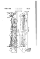
March 29, 1932. T. H. BROADHURST PAPER MAKING MACHINE Filed July 21, 1928 2 Sheets-Sheet ATTORNEYS March 29, 1932. BROADHURST 1,851,941
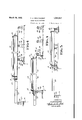
PAPER MAKING MACHINE Filed July 21, 1928 2 Sheets-Sheet 2 FIG. 5
. INVENTOR I: III-LBROADHURST O- ATTORNEYS Patented M529, 1932 THOMAS H. BBOADKUBST, O1 MONTREAL,
QUEBEC, CAIlAIJA, ABBIGI'OB TO CHARLES WALHSLEY & COMPANY (CANADA) LIMITED, 01' MONTREAL, CANADA PAPER MAKING MACHINE Application fled July 21,
This invention relates to new and useful improvements in pager making machines and particularly to the ourdrinier type of machine in which the table is-moved laterally 5 when placing a new wire thereon. The main object of the invention is to simplify the construction of the machine so that the wire may be quickly and readily changed without removing any of the parts, such as wire suplo porting parts, drain boxes, and the like,
mounted in the bed of the machme. 7
Another object is to provide novel and'efiicient means for movin the table in the transverse direction to facihtate the placing of the 1:. wire thereon with the minimum of labour and expense.
As disclosed herein the invention contemplates the provision of a table having'a frame including spaced side members connected by transverse rail forming members. When the 4 table is in its operative position, the rail forming members rest on a plurality of main supportin rollers carried by stationary posts secure to the underlying floor structure. Certain of the main supporting rollers are rotated, at times, by suitable power operated mechanism supported independentl of the table mechanism. When so rotated t ese rollers co-operate with the engaging rail form- Iill ing members to propel the table laterally from an operative to an ino erative osltlon, or vice versa. pDuring shi ting of t e table to an inoperative position, the leading end of at least certain of the rail forming members are brought into engagement with supplementary supporting rollers arranged in the aisle beside the machine, these supplementary rollers being carried by stationary posts aligned with the rail forming members 40 adapted to be supported thereby. Su1table arms are hinged to the side of the table frame remote from the aisle into which the table is shifted during the wire changing operation, the hinge connections being located so that the arms, when swung to a posltion at was. Serial in. 294,441.
right angles to the table frame, are ali ed With certain of the transverse rail mem rs to provide continuations thereof. The arms are extended from the table when the latter is to be shifted to an in operative position and serve, during a portion of the shifting operation, to bridge the gap that would otherwise be left between the trailing side of the moving table and the main rollers normally supporting said side. In this way, tiltin of the table during lateral movement is e ec- .tively avoided. When displacement of the table to an inoperative position is complete, the extension arms are folded fiat against the ad acent s1de of the table frame to prevent interference with the wire changing operacertain elements of the machine are rearranged on the table to facilitate the wire I changing operation.
Fig. 3 is an end elevation showing the table in operative position with the supporting arms extending outwardly therefrom.
Fig. 4 is an end elevation partly in sectign showing the table supported at an intermediate point during its travel from an operative to an inoperative position, or vice versa.
Fig. 5 is an end elevation partly in section showing; the manner in which the table is supported in laterally displaced position at one side of its normal or operative position.
Referring more particularly to the drawings, 11 and 12 designate the side members 99 of a laterally movable Fourdrinier table suppgrting at one end thereof the usual suction xes 13 and table rolls14, the latter being suction roll 19 is shown at the opposite end of the machine and the endless wire 20 passes around the suction and breast rolls with the up r reach of the wire resting on the table rol s and suction boxes in the usual manner.
15 The lower reach of the wire passes beneath the table in contact with the guide and carrying rolls 21 and tension roll 22, these rolls being respectivel mounted in the bearings 23 and 24. The sidla members 11 and 12 of the 2 table are connected by'transversely extending rail forming members appearing at 25 and 26. r In the present instance, three rail forming members are provided, including an intermediate member 25 'havin surface 27 and a pair of en members 26 having their lower surfaces provided with serrations or teeth 28. A pair of arms 29havin smooth lower surfaces are hinged to the ta le member 12 at points in line with the rail forming members 26 and are adapted to be swung into and outof alignment with said members 26. Th'ese'arms, when not in use, fold flat a ainst the side member 12.
When the tal le is hits 0 rative position above the floor pit A (see ig. 3), the side 12 rests on a series of main supporting rollers indicated at 32. These rollers 32 are journalled in stationary posts 33 mounted on the floor structure at the side of the pit remote when displaced laterall to an inoperative position, as hereinafter escribed. Only one roller 32 appears in the drawing, but it will be understood that three of theserollers are provided and that the two end rollers are located in line with the rail forming members 26 while the intermediate roller is located in line with the remaining rail forming member 25. Additional main supporting rollers 34, 4
corresponding in number to the rollers 32, are journalled in posts 35 arranged immediately adjacent the aisle side of the pit A and serve to support the side 11 of the table when the table is in the position shown in Fig. 3. Each roller 34 is ahgned wth one of the rollers 32 and is adapted to rotate in supporting engagement with the underside ofone of the rail forming members of the table during movement of the table from the position shown in Fig. 3 to the position shown in Fig. 5, or vice versa. The rollers 34, engaging the rail forming members 26, are equipped with teeth or serrations 36 meshing with the teeth or serrations 28 to provide rack and pinion means for propelling the table latera smooth lower from the aisle B into which the table is moved ally to and from the positions shown in Figs. 3 and 5. The toothed or serrated rollers 34 are carried by spindles 37 which are connected by belts or chain drives 38 to a power driven shaft 39. Shaft 39 is driven throughv caring 40 by a motor 41 and is journalled in arings 42. Shaft 39 is also manually operable through the medium of a gear 43 fixed to'said shaft and meshing with a pinion 44 positioned between bearings 45 and fixed to a s indle 46 journalled in said bearings. One en of the spindle 46 is extended and squared, as indicate at 47 to provide for the attachment of a handle thereto, in the event that the motor 41 is rendered inoperative by current failure or other causes. When the table is displaced to an inoperative position within the aisle B, as shown in Fig. 5, it will be noted that the side 12 is supported by the rollers 34 while the side 11 and the intermediate portion of the table are supported by auxihary rollers 48 journalled in supporting posts 49 mounted in the aisle B. Preferably, two laterally spaced auxiliary rollers 48 are arranged in line with each of the main supporting rollers 34 but this is optional since it is notabsolutely necessary to provide any auxiliary supporting rollers 48 in line with the rollers 34 supporting the rail forming member 25 of the table. As a matter of fact, therollers 32 and 34 co-operating with the rail formin member 25'may also be dis ensed with an the table supported in both its operative and ino rative position solely by means of the rol ers 32, 34nd 48 co-operating with the rail forming members 26.
In the use of-this invention, the paper making .wire when worn iscut and withdrawn from the machine. The breast roll 16 is then lifted from its bearing 17 andlaced on suitable supporting faces provid for this purpose at the breast roll end of the table as shown to advantage in Fig. 2. Certain of the tablerolls are also removed from their normal positions and piled upon the remaining rolls. The arms 29 are next swun into a position of alignment with the rall form ng members 26 of the table. The motor 41 is now 0 rated to rotate the toothed rollers 34 in a direction to propel the table to the right from the position shown in Fig. 3. During this movement of the table, the leading ends of the rail forming members 25 and 26 pass into supporting en gement with the auxiliary supporting ro ers 48. As the trailing edge of the table proper moves out of supporting engagement with the rollers 32, the arms 29 are brought into engagement with these rollers and serve to hold the table level until thetable has moved to a position where the center of gravit is located at the right. of the supporting ro ers 34. When the table is in its full displaced or inoperative position it is supported (partly b the main supporting rollers 34 an partly y the auxiliary supporting rollers 48, it being noted in this, con-' nection that the toothed or serrated rollers 34 are, at all times, in propelling engagement with the rail forming members 26. After the table reaches the position shown in Fig. 5,
' the arms 29 are swung inwardly to lie flat against the side member 12 and thus avoid interference. with the wire placing opera-- tion. As shown in Fig. 2, one of the wire tensioning rolls is removed and the new wire the table and the parts of the machine moun't-' ed on the table are permitted to pass freely during return movement of the table to its operative position; In effecting this return movement of the table, the arms 29 are again swung to extended position so that as the table is moved to the left from the position shown in Fig. 5 to the position shown in Fig. 3, these arms are brought'into supporting engagement with the rollers 32 as the right hand portion of the table is moving out of engagement with the right hand auxiliary supporting rollers 48, the horizontal position of the table being maintained by the auxiliary rollers 48 located nearest to the rollers 34, until the table has travelled to the left to a position where the center of gravity is located to the left of the rollers 34. After return of the table to its operative position, the supports 51 are withdrawn and the breast roll 16 reengaged with its bearing 17 while at the same time the displaced wire supporting rolls 14 are returned to their normal positions on the table. The previously removed tensioning roll is then replaced in, position and serves to draw the wire into contact with the suction boxes, table rolls, breast roll and suction roll so that the machine is again ready to receive paper stock from the head box outlet 18.
Having thus described my invention, what I claim is 1. A Fourdrinier paper machine equipped with a laterally movable table, rollers mounted independently of the table and arranged to support the table in either an operative or a laterally displaced position, and means for rotating certain of the rollers to propel the table to or from either of said positions.
2. A Fourdrinier paper machine equipped with a laterally movable table, main supporting rollers bearing against the table to support the table in operative position, auxiliary rollers arranged to bear against the-table to assist in supporting the table when the table is in a laterally displaced position and means for rotating certain of the main supporting rollers to propel the table to or from either of said positions.
3. A Fourdrinier paper machine equipped with a laterally movable table, rollers mounted independently of the table and arranged to support the table in either an operative or a laterally displaced position and means for driving certain of the rollers to propel the table to or from either of said positions, said driven rollers being in direct, uninterrupted propelling engagement with the table in all positions of the latter.
4. A F ourdrinier paper machine equipped with a laterally movable table, extension arms hinged to said table and adapted to be extended therefrom during lateral movement of the table, independently mounted rollers arranged to support the undersides of the table and arms during lateral movement thereof, and means for driving certain of said rollers to furnish the power for moving the table laterally. 5. A F ourdrinier paper machine equipped with a laterally movable table including transverse rail members, extension arms hinged to the table totravel therewith, said arms being adapted to be extended from the table to form continuations of the rail members during lateral movement of the table, independently mounted rollers arranged to engage the undersides of the rail members and extension arms to support the same during lateral movement, and means for rotating certain of said rollers to propel the table from an operative to a laterally displaced position and vice versa.
6. A Fourdrinier paper machine equipped with a laterally movable table having a frame including side members connected by transverse rail forming members, a plurality of independently mounted main supporting rollers arranged so that the side members of the table frame rest thereon when the table is in its operative position, auxiliary supporting rollers arranged in laterally spaced relation to the table when the table is in said operative position, said table being movable laterally from its operative position to a lat erally displaced position wherein the table is supported partly by the auxiliary rollers and partly by certain of the main rollers, and
means for rotating certain of said main rollers to propel the table laterally in either direction, said propelling rollers acting against the undersides of the rail forming members during movement of the table.
7. A Fourdrinier paper machine equipped with a laterally movable table including side members connected by transverse rail forming members, arms hinged to one of said side members and adapted to be extended outwardly therefrom to form continuations of the rail forming members, main supporting rollers arranged to support the table in its operative position and to bear against the undersides of the rail forming members and the extended arms during movement of the table 4 1,au,o41
from its operative to a laterally displaeed .position or vice versa, auxiliary supporting rollers arranged to bear against the underside of therail forming members when thev "table is in its laterally displaced position,
' and means for driving certain of the main supporting rollers to propel the table to and from either of said positions, the eontacti surfaces'of the driving rollers and the ra 10 forming members being formed to provide a rack and pinion drive connection therebetween.
In witness whereof, I have hereunto set my hand.
15 THOMAS H. BROADHURST.
Priority Applications (1)
| Application Number | Priority Date | Filing Date | Title |
|---|---|---|---|
| US294441A US1851941A (en) | 1928-07-21 | 1928-07-21 | Paper making machine |
Applications Claiming Priority (1)
| Application Number | Priority Date | Filing Date | Title |
|---|---|---|---|
| US294441A US1851941A (en) | 1928-07-21 | 1928-07-21 | Paper making machine |
Publications (1)
| Publication Number | Publication Date |
|---|---|
| US1851941A true US1851941A (en) | 1932-03-29 |
Family
ID=23133435
Family Applications (1)
| Application Number | Title | Priority Date | Filing Date |
|---|---|---|---|
| US294441A Expired - Lifetime US1851941A (en) | 1928-07-21 | 1928-07-21 | Paper making machine |
Country Status (1)
| Country | Link |
|---|---|
| US (1) | US1851941A (en) |
Cited By (5)
| Publication number | Priority date | Publication date | Assignee | Title |
|---|---|---|---|---|
| US2799209A (en) * | 1952-03-28 | 1957-07-16 | Black Clawson Co | Fourerinier papermaking machine |
| US2870691A (en) * | 1952-03-28 | 1959-01-27 | Black Clawson Co | Fourdrinier paper making machine |
| US4200490A (en) * | 1978-07-21 | 1980-04-29 | Scapa Canada Ltee | Method and apparatus for handling rolls inside an endless paper-making belt |
| EP0308029A1 (en) * | 1987-09-15 | 1989-03-22 | Oy Tampella Ab | Frame construction of the press section in a paper machine |
| EP0308028A1 (en) * | 1987-09-15 | 1989-03-22 | Oy Tampella Ab | Press section in a paper machine |
-
1928
- 1928-07-21 US US294441A patent/US1851941A/en not_active Expired - Lifetime
Cited By (7)
| Publication number | Priority date | Publication date | Assignee | Title |
|---|---|---|---|---|
| US2799209A (en) * | 1952-03-28 | 1957-07-16 | Black Clawson Co | Fourerinier papermaking machine |
| US2870691A (en) * | 1952-03-28 | 1959-01-27 | Black Clawson Co | Fourdrinier paper making machine |
| US4200490A (en) * | 1978-07-21 | 1980-04-29 | Scapa Canada Ltee | Method and apparatus for handling rolls inside an endless paper-making belt |
| EP0308029A1 (en) * | 1987-09-15 | 1989-03-22 | Oy Tampella Ab | Frame construction of the press section in a paper machine |
| EP0308028A1 (en) * | 1987-09-15 | 1989-03-22 | Oy Tampella Ab | Press section in a paper machine |
| US4879002A (en) * | 1987-09-15 | 1989-11-07 | Oy Tampella Ab | Frame construction of the press section in a paper machine |
| US4922990A (en) * | 1987-09-15 | 1990-05-08 | Oy Tampella Ab | Press section frame in a paper machine |
Similar Documents
| Publication | Publication Date | Title |
|---|---|---|
| US2736507A (en) | Winder shaft puller and table | |
| US1851941A (en) | Paper making machine | |
| US3747387A (en) | Roll changing arrangement for a rolling mill | |
| US2130233A (en) | Roll lift stand | |
| US2266067A (en) | Coil feeding apparatus | |
| US3341148A (en) | Take-up apparatus | |
| US1924100A (en) | Drier | |
| US3728772A (en) | Tape breaker (case 1) | |
| US1591597A (en) | Web-roll-changing system | |
| US1678176A (en) | Removable-type fourdrinier paper-making machine | |
| JPS6236275A (en) | Cloth extending machine | |
| US2047422A (en) | Fourdrinier paper making machine | |
| US2003103A (en) | Means and method of stringing a fourdrinier wire | |
| US1678894A (en) | Paper-roll-changing plant | |
| US1827802A (en) | Papee winding machine | |
| US1759676A (en) | Driven slitter for paper-slitting machines | |
| US2829845A (en) | Coil winding apparatus | |
| US1828297A (en) | Web roll support | |
| US1457822A (en) | Machine for and process of producing rolls of paper for towels, toilet paper, etc | |
| US2742964A (en) | Cloth cutting table and machine | |
| US1389906A (en) | Fabric-laying apparatus | |
| US1807813A (en) | Roll changer | |
| US1792558A (en) | Lap-folding device for wet machines | |
| US1484842A (en) | Slitting and rewinding machine | |
| US1086967A (en) | Cloth-working machine. |