US1851908A - Roller swing - Google Patents
Roller swing Download PDFInfo
- Publication number
- US1851908A US1851908A US418974A US41897430A US1851908A US 1851908 A US1851908 A US 1851908A US 418974 A US418974 A US 418974A US 41897430 A US41897430 A US 41897430A US 1851908 A US1851908 A US 1851908A
- Authority
- US
- United States
- Prior art keywords
- shaft
- rollers
- tracks
- roller swing
- horizontal
- Prior art date
- Legal status (The legal status is an assumption and is not a legal conclusion. Google has not performed a legal analysis and makes no representation as to the accuracy of the status listed.)
- Expired - Lifetime
Links
Images
Classifications
-
- F—MECHANICAL ENGINEERING; LIGHTING; HEATING; WEAPONS; BLASTING
- F16—ENGINEERING ELEMENTS AND UNITS; GENERAL MEASURES FOR PRODUCING AND MAINTAINING EFFECTIVE FUNCTIONING OF MACHINES OR INSTALLATIONS; THERMAL INSULATION IN GENERAL
- F16H—GEARING
- F16H7/00—Gearings for conveying rotary motion by endless flexible members
- F16H7/18—Means for guiding or supporting belts, ropes, or chains
-
- Y—GENERAL TAGGING OF NEW TECHNOLOGICAL DEVELOPMENTS; GENERAL TAGGING OF CROSS-SECTIONAL TECHNOLOGIES SPANNING OVER SEVERAL SECTIONS OF THE IPC; TECHNICAL SUBJECTS COVERED BY FORMER USPC CROSS-REFERENCE ART COLLECTIONS [XRACs] AND DIGESTS
- Y10—TECHNICAL SUBJECTS COVERED BY FORMER USPC
- Y10T—TECHNICAL SUBJECTS COVERED BY FORMER US CLASSIFICATION
- Y10T74/00—Machine element or mechanism
- Y10T74/18—Mechanical movements
- Y10T74/18992—Reciprocating to reciprocating
-
- Y—GENERAL TAGGING OF NEW TECHNOLOGICAL DEVELOPMENTS; GENERAL TAGGING OF CROSS-SECTIONAL TECHNOLOGIES SPANNING OVER SEVERAL SECTIONS OF THE IPC; TECHNICAL SUBJECTS COVERED BY FORMER USPC CROSS-REFERENCE ART COLLECTIONS [XRACs] AND DIGESTS
- Y10—TECHNICAL SUBJECTS COVERED BY FORMER USPC
- Y10T—TECHNICAL SUBJECTS COVERED BY FORMER US CLASSIFICATION
- Y10T74/00—Machine element or mechanism
- Y10T74/21—Elements
- Y10T74/2142—Pitmans and connecting rods
- Y10T74/2159—Section coupled
Definitions
- This invention relates toimp'rovements in vertical roller swings or guides for pump operating rods.
- the primary object of the invention is to furnish a roller swing, which will function either to hold the rod line up or down, de-. pending on whether the line is extending across a hill or valley.
- a further object is to provide a roller swing of this character, which will, function indefinitely without getting out of order, and in actual practice, over a considerable period of time, some of these swings have functioned ver efiiciently and have operated with very litt 0 care.
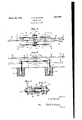
- Fig. 1 is a top plan view of my improved roller swing.
- Fig. 2 is a side elevation of the same, with the rollers arranged to hold the rod line up.
- This view also shows in dotted lines, the ar-..
- 5 indicates a pair of inverted U-shaped tracks which are arranged side b side, and have the lower end portion of their legs embedded in masses of concrete 6 which are placed in holes in the ground 7 at the point where the swin is to be used.
- These masses of concrete ave sufficient weight to hold the horizontal portions 8 of the tracks in proper position relatively to the ground surface, whether the swing is used to hold the rod line up or down.
- Fig. 2 they are shown as holding the rod line up in full lines, and as holding the same down, in dotted mes.
- the track portions 8 of the guides are of any suitable shape, so as to conform to the peripheries of a pair of rollers 9.
- the tracks may be of cylindrical form, and the rollers may have grooves, the surfaces of which conform to the tracks.
- these rollers are rotatably mounted on a hollow shaft 10 which is adapted to be filled with a suitable lubricant that is fed to the inner surfaces of the rollers by "means of apertures 11 in the wall of the hollow shaft.
- One of the rollers may be detachably mounted on the shaft by means of a cotter pin 12 or the like, so as to allow a pair of eye subs or connections 13 to be connected to the intermediate portion of the shaft.
- the outer ends of these subs may be connected by any suitable plamping device 14, to a portion 15 of the rod
- Another eye sub or connection 16 has its eye 17 arranged on the shaft, between the eyes 18 of the pair of subs, and the sub 16 may have its outer end upset, if desired, as shown at 19, so that it can be connected to another portion of the pump rod line.
- t e rollers may engage the under sides of the tracks 8, where the rod line is across a valley, and the roller swing is used as a hold-down.
- the construction may be such that the shaft 10a will rotate with the rollers 9a as shown in Fig. 3.
- the eyes lia and 18a of the subs might enga a sleeve 20 which is pivotally mounted on t e shaft.
- the journal can'be lubricated by means of a grease cup 21.
- a roller swing comprising weight
- inverted U-shaped track members having legs rigidly connected with said masses, each track member having a substantially horizontal portion, rollers having thelr peripheries shaped to roll either on the top or bottom surfaces of the substantially horizontal portions of the track members, a shaft extending through and connecting said rollers, and means for connecting the shaft to portions of a rod line.
- a roller swing for guiding a rod line comprising weight masses adapted to be embedded in the ground, substantially inverted U-shaped track members havin legs rigidly connected with said masses, each track member having a substantially horizontal cylindrical portion which is held in elevated position by the legs of that track member, rolls having grooved peripheries engaging said s bstantial y horizontal cylindrical portions of the tracks, a shaft connecting said rollers, and means for connecting the shaft to portions of a rod line.
- a roller swing for guiding a pump rod line or the like including a pair 0 horizontally disposed weighted tracks, a plurality of rollers engageable with and shaped to roll 4.
- a roller swing for guiding pump rod lines or the like comprising a pair of inverted U-shaped tracks having their legs embedded-in weight masses, each track having a horizontal portion, rollers adapted to roll eitheron the top or bottom surfaces of the horizontal portions of said tracks, a horizontal shaft on which the rollers are mounted, and subs pivotally connected to said shaft for swinging movement upwardly or downwardly and adapted to be interposed in a pump rod line or the like.
- a roller swing for guiding pump rod lines or the like including spaced horizontal tracks having supporting legs, means for weighting said legs to prevent the track from moving upwardly, a horizontal shaft rollers journaled on said shaft and shape to roll on the top or bottom surfaces of the tracks, and 'subs pivotally connected to the shaft for swinging movement upwardly or downwardly and adapted to be interposed in arod line.
- weights adapted to be embedded in the ground substantially inverted U-shaped tracks having legs embedded in the masses, each track having a horizontal portion, a horizontal shaft, rollers journaled on the shaft and shaped to roll on either the top or bottom surfaces of the horizontal portions of the tracks, and subs pivotally con nected to the shaft for swinging movement upwardly and downwardly and adapted to be interposed in a rod line.
- a roller swing for guiding a rod line comprising spaced parallel horizontal tracks, a horizontal shaft, rollers shaped to roll on the top or bottom surfaces of said tracks and journaled on said shaft, and oppositely extending subs pivotally connected to the shaft for swinging movement upwardly and downwardly between said tracks.
- roller swing for guiding a rod line comprising a pair of spaced substantially horizontal track members, a horizontal shaft, rollers fixed to said shaft and adapted to roll on either the top or bottom surfaces of said track members, and subs pivotally connected 4 to the shaft between said rollers.
Landscapes
- Engineering & Computer Science (AREA)
- General Engineering & Computer Science (AREA)
- Mechanical Engineering (AREA)
- Bearings For Parts Moving Linearly (AREA)
Description
March 29, 1932. c, w, HOOVER 1,851,908
ROLLER SWING Filed Jan. 6, 1930 gwuwntoa C. W Hoover;
Mam/m panyin Patented Mar. 29 193? urn-T121 STATES. PATENT OFFICE CHARLES W. HOOVER, OF BURIBANK, OKLAHOMA, ASSIGNOR TO PHILLIPS PETROLEUM COMPANY, OF BARTLESVILLE, OKLAHOMA, A CORPORATION OF DELAWARE ROLLER SWING Application filed January 6, 1930. Serial No. 418,974.
This invention relates toimp'rovements in vertical roller swings or guides for pump operating rods.
It is well known that when an oil field be-- line in puinping, and the present invention relates to a roller swing or guide to handle the rod line over uneven surfaces.
The primary object of the invention is to furnish a roller swing, which will function either to hold the rod line up or down, de-. pending on whether the line is extending across a hill or valley.
A further object is to provide a roller swing of this character, which will, function indefinitely without getting out of order, and in actual practice, over a considerable period of time, some of these swings have functioned ver efiiciently and have operated with very litt 0 care.
With the foregoing objects outlined and with other objects in view which will appear as the description proceeds, the invention consists in the novel features hereinafter described in detail, illustrated in the accomdrawings, and more particularly pointe out in the a nded claims.
Referring to the rawings,-
Fig. 1 is a top plan view of my improved roller swing.
Fig. 2 is a side elevation of the same, with the rollers arranged to hold the rod line up.
This view also shows in dotted lines, the ar-..
rangement of the parts when used as a holdown- Fig. 3 is a vertical sectional view of a modification.
In the drawings, 5 indicates a pair of inverted U-shaped tracks which are arranged side b side, and have the lower end portion of their legs embedded in masses of concrete 6 which are placed in holes in the ground 7 at the point where the swin is to be used. These masses of concrete ave sufficient weight to hold the horizontal portions 8 of the tracks in proper position relatively to the ground surface, whether the swing is used to hold the rod line up or down. In Fig. 2, they are shown as holding the rod line up in full lines, and as holding the same down, in dotted mes.
It will be observed that the track portions 8 of the guides are of any suitable shape, so as to conform to the peripheries of a pair of rollers 9. For example, the tracks may be of cylindrical form, and the rollers may have grooves, the surfaces of which conform to the tracks. In the form of the invention illustrated in Figs. 1 and 2, these rollers are rotatably mounted on a hollow shaft 10 which is adapted to be filled with a suitable lubricant that is fed to the inner surfaces of the rollers by "means of apertures 11 in the wall of the hollow shaft.
One of the rollers may be detachably mounted on the shaft by means of a cotter pin 12 or the like, so as to allow a pair of eye subs or connections 13 to be connected to the intermediate portion of the shaft. The outer ends of these subs may be connected by any suitable plamping device 14, to a portion 15 of the rod Another eye sub or connection 16 has its eye 17 arranged on the shaft, between the eyes 18 of the pair of subs, and the sub 16 may have its outer end upset, if desired, as shown at 19, so that it can be connected to another portion of the pump rod line.
It will be understood that the eyes 17 and-- 18 hinge on the shaft, but in the constructlon shown in Figs. 1 and 2, the shaft, due to the pull of the pump rod line, is held from rotatmg, and it is only the rollers 9 WhlCh rotate as the shaft reciprocates back and forth on the tracks 8. 7
It ma be seen from the dotted lines in Fig.- 2, that t e rollers may engage the under sides of the tracks 8, where the rod line is across a valley, and the roller swing is used as a hold-down.
It is manifest that. the construction may be such that the shaft 10a will rotate with the rollers 9a as shown in Fig. 3. In such case, the eyes lia and 18a of the subs might enga a sleeve 20 which is pivotally mounted on t e shaft. In such a construction, the journal can'be lubricated by means of a grease cup 21.
When the device is .used as a hold-up, the force tends to push the pipes 5, further into the ground, but as the concrete masses 6 form relatively broad foundations, it will be understood that they will prevent sinking of the tracks. On the other hand, when the roller swing is used as a hold-down, the rollers are placed underneath the tracks 8, and the weight of the concrete more than offsets the force tending to lift-the pipes 5.
Those skilled in the art will clearly understand that with a roller swing of the character described, the rod line will be prevented from dragging on the ground surface, and the line will endure for a much greater length of time than if it were allowed to drag and thus wear.
lVhile I have disclosed what I now consider preferred embodiments of the invention in such manner that the construction, 9 eration and advantages of the invention may e readily understood, I am aware that changes may be made in the details disclosed, without departing from the spirit of the invention, as ex ressed in the claims.
at I claim and desire to secure by Letters Patent is:
1. A roller swing comprising weight,
masses adapted to be embedded in the ground, substantially. inverted U-shaped track members having legs rigidly connected with said masses, each track member having a substantially horizontal portion, rollers having thelr peripheries shaped to roll either on the top or bottom surfaces of the substantially horizontal portions of the track members, a shaft extending through and connecting said rollers, and means for connecting the shaft to portions of a rod line.
2. A roller swing for guiding a rod line, comprising weight masses adapted to be embedded in the ground, substantially inverted U-shaped track members havin legs rigidly connected with said masses, each track member having a substantially horizontal cylindrical portion which is held in elevated position by the legs of that track member, rolls having grooved peripheries engaging said s bstantial y horizontal cylindrical portions of the tracks, a shaft connecting said rollers, and means for connecting the shaft to portions of a rod line.
3. A roller swing for guiding a pump rod line or the like, including a pair 0 horizontally disposed weighted tracks, a plurality of rollers engageable with and shaped to roll 4. A roller swing for guiding pump rod lines or the like, comprising a pair of inverted U-shaped tracks having their legs embedded-in weight masses, each track having a horizontal portion, rollers adapted to roll eitheron the top or bottom surfaces of the horizontal portions of said tracks, a horizontal shaft on which the rollers are mounted, and subs pivotally connected to said shaft for swinging movement upwardly or downwardly and adapted to be interposed in a pump rod line or the like.
5. A roller swing for guiding pump rod lines or the like, including spaced horizontal tracks having supporting legs, means for weighting said legs to prevent the track from moving upwardly, a horizontal shaft rollers journaled on said shaft and shape to roll on the top or bottom surfaces of the tracks, and 'subs pivotally connected to the shaft for swinging movement upwardly or downwardly and adapted to be interposed in arod line.
6. In combination, weights adapted to be embedded in the ground, substantially inverted U-shaped tracks having legs embedded in the masses, each track having a horizontal portion, a horizontal shaft, rollers journaled on the shaft and shaped to roll on either the top or bottom surfaces of the horizontal portions of the tracks, and subs pivotally con nected to the shaft for swinging movement upwardly and downwardly and adapted to be interposed in a rod line.
7. A roller swing for guiding a rod line, comprising spaced parallel horizontal tracks, a horizontal shaft, rollers shaped to roll on the top or bottom surfaces of said tracks and journaled on said shaft, and oppositely extending subs pivotally connected to the shaft for swinging movement upwardly and downwardly between said tracks.
8. roller swing for guiding a rod line, comprising a pair of spaced substantially horizontal track members, a horizontal shaft, rollers fixed to said shaft and adapted to roll on either the top or bottom surfaces of said track members, and subs pivotally connected 4 to the shaft between said rollers.
specification.
CHARLES W. HOOVER.
Priority Applications (1)
| Application Number | Priority Date | Filing Date | Title |
|---|---|---|---|
| US418974A US1851908A (en) | 1930-01-06 | 1930-01-06 | Roller swing |
Applications Claiming Priority (1)
| Application Number | Priority Date | Filing Date | Title |
|---|---|---|---|
| US418974A US1851908A (en) | 1930-01-06 | 1930-01-06 | Roller swing |
Publications (1)
| Publication Number | Publication Date |
|---|---|
| US1851908A true US1851908A (en) | 1932-03-29 |
Family
ID=23660289
Family Applications (1)
| Application Number | Title | Priority Date | Filing Date |
|---|---|---|---|
| US418974A Expired - Lifetime US1851908A (en) | 1930-01-06 | 1930-01-06 | Roller swing |
Country Status (1)
| Country | Link |
|---|---|
| US (1) | US1851908A (en) |
Cited By (1)
| Publication number | Priority date | Publication date | Assignee | Title |
|---|---|---|---|---|
| US8083499B1 (en) | 2003-12-01 | 2011-12-27 | QuaLift Corporation | Regenerative hydraulic lift system |
-
1930
- 1930-01-06 US US418974A patent/US1851908A/en not_active Expired - Lifetime
Cited By (2)
| Publication number | Priority date | Publication date | Assignee | Title |
|---|---|---|---|---|
| US8083499B1 (en) | 2003-12-01 | 2011-12-27 | QuaLift Corporation | Regenerative hydraulic lift system |
| US8562308B1 (en) | 2003-12-01 | 2013-10-22 | Rodmax Oil & Gas, Inc. | Regenerative hydraulic lift system |
Similar Documents
| Publication | Publication Date | Title |
|---|---|---|
| CA2732565C (en) | Auto-centering structural bearing | |
| US1851908A (en) | Roller swing | |
| US1706332A (en) | Posthole digger | |
| US1982482A (en) | Rod spider | |
| US1566451A (en) | Sucker-rod antifriction means for well tubing | |
| US1825096A (en) | Rocker bearing for walking beams | |
| US2228709A (en) | Boring rifler | |
| US2060188A (en) | Rod line support | |
| US2722850A (en) | Power reducer for pumping wells | |
| US1860121A (en) | Weighted rod line swivel | |
| Boonsri | Torque simulation in the well planning process | |
| US1787164A (en) | Pumping jack | |
| US1466620A (en) | Fishing tackle | |
| US1841712A (en) | Pumping jack for oil wells | |
| US1766387A (en) | Lubricator for car journals | |
| US1953903A (en) | Pumping jack | |
| US1707721A (en) | Elevator hook | |
| US2737367A (en) | Oil well mast crown block | |
| US1750021A (en) | Oil-well pumping jack | |
| US2900160A (en) | Swing-hook assembly | |
| DE711095C (en) | Suspension device for a centrifugal machine | |
| US1606273A (en) | Suspension hook | |
| US2053705A (en) | Rod line carrier | |
| US2090817A (en) | Clam bucket | |
| DE468890C (en) | Storage for drill handle |