US1851907A - Air brakes for aircraft - Google Patents
Air brakes for aircraft Download PDFInfo
- Publication number
- US1851907A US1851907A US507734A US50773431A US1851907A US 1851907 A US1851907 A US 1851907A US 507734 A US507734 A US 507734A US 50773431 A US50773431 A US 50773431A US 1851907 A US1851907 A US 1851907A
- Authority
- US
- United States
- Prior art keywords
- resistance
- hinge
- aircraft
- angular adjustment
- braking position
- Prior art date
- Legal status (The legal status is an assumption and is not a legal conclusion. Google has not performed a legal analysis and makes no representation as to the accuracy of the status listed.)
- Expired - Lifetime
Links
Images


Classifications
-
- B—PERFORMING OPERATIONS; TRANSPORTING
- B64—AIRCRAFT; AVIATION; COSMONAUTICS
- B64C—AEROPLANES; HELICOPTERS
- B64C9/00—Adjustable control surfaces or members, e.g. rudders
- B64C9/32—Air braking surfaces
-
- B—PERFORMING OPERATIONS; TRANSPORTING
- B64—AIRCRAFT; AVIATION; COSMONAUTICS
- B64C—AEROPLANES; HELICOPTERS
- B64C9/00—Adjustable control surfaces or members, e.g. rudders
- B64C9/32—Air braking surfaces
- B64C9/323—Air braking surfaces associated with wings
Definitions
- This invention relates to air brakes for application to the trailing edge of aircraft wings, the object of the invention being to increase the resistance of such wings when sition.
- the brakes may befitted to extend to any distance laterally to the line of flight, and the aim of the invention is so to construct the said brakes that they may be operated to apply the braking effect with a minimum of power to be exerted manually by the operator of the machine.
- auxiliary pivoted surface which auxiliary pivoted surface in itself acts as a servo-surface to operate the mam surface which main surface would it exert too great resistance for convenient larly adjustable about a hinge which is permitted to travel bodily backwards relatively to the direction of flight in proportion to the angular adjustment given to the resistance surface.
- the surface instead of being angularly adjustable at its leading edge 'is angularly adjustable about a hinge distanced from the plane of the resistance surface.
- This movement may be secured about a single the two angularly ad ustable resistance surhinge, or where it is )desired that the leading edge of the resistance surface shall be retained in the line of the chord of themain surface, links may be provided which permit the leading edge of the surface to travel back I wards in the plane of the wing chord while the resistance surface itself is increasing in angular adjustment as the leading ed e of such surface is moving in a rearward irection.
- the invention is particularly suitable for air brakes in which there are two surfaces angularly adjustable in opposite directions simultaneously.
- both surfaces are hinged together and the hinged portion is caused to travel backwards while the. surfaces open about their hinge'in opposite directions.
- the resistance surface will be controlled in such adjustment by link motions or other means for determining the proportion of mutual angular adjustment to the total bodily displacement in a rearward direction.
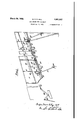
- Figure l is a plan .view illustrating a fragmentary part of the Wing of aircraft, and illustrating the application of the resistance surface to said wing, with the resistance surface in its non-effective position. -Only the upper resistance surface is seen in the figure, the other surface being underneath the wing immediately belowthe resistance surface shown.
- Figure 2 is a similar view to Figure 1, but
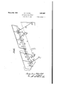
- Figure 3 is an'end view of the wing with faces A A are each'provided with tubular members A fixed in bearings A on flanges A of the resistance surfaces. carry inwardlyextending arms A, the inner ends of which arms are hinged together by These tubes a hinge pin B. .
- the tube of each resistance I surface is also provided with'outwardly extending arms A the outer ends of which are anchored at A to anchor rods A fixed at A to the wingof the aircraft.
- the hinge pin B extends longitudinally along the resistance surface and is connected to the apices B of triangular links consisting of members B B and B. These triangular links are mounted at a corner. B remote from the hinge on a bracket B fixed to the rear spar C of the wing.
- the links B are connected together by the connecting member B and to a bell crank lever B by a rod B", which bell crank lever B is operable in a lateral direction .from the position where the pilot is located in the fuselage, by means of the cable B.
- the triangular links B B and B can be moved from the position shown in Figure 1 to the position shown in Figure 2 in which the hinge pin B is moved rearwardly relatively to the direction of flight. In this movement, due to the anchorage of the arms A, the resistance surfaces are caused to open apart in proportion to the rearward travel of the said hinge.
- the resistance surfaces not only move rearwardly with their angular outward adjustment, but also move to some extent in a lateral direction as will be seen from Figure 2 of the accompanying drawings.
- the necessity for this partial lateral movement may be avoided by causing the hinge to move in a straight path in a rearward direction, which movement could be secured by providing a link or other means of control to project the hinge bodily straight triangular links.
- the operation'of the airbrake on one wing may be independent of the operation of the air brake on the other wing
- the rudder bar may be operated in the ordinary manner for the purpose of angularly opening the brake surfaces on'one side only or to over-control the brake lever, which, in the normal way, would be used to open both brakes simultaneously.
- an independent brake lever would be employed which would tend to open both brakes, but by the application of the rudder bar, a variable resistance would be secured by the ruddering action applying appropriate brake resistance without interference by the brake lever.
- the brake lever preferably returns to neutral when letgo, and it may be assisted to remain holding the brakes on by a catch which supports most of the resistance to return to neutral, thus preventing the brake being left on accidentally.
- the resistance surfaces are inset in the trailing edge of the wing but, alternatively these resistance surfaces could be mounted on outrigger arms behindthe trailing edge of the wing. In this outstanding position behind the wing, the resistance surfaces when closed would appear like control surfaces but the action of the brake surfaces would be as liereinbefore described.
- the steepness of the glide of the aircraft may be considerably increased, thus facilitating lidiiig into a small field While permitting of the maintenance of the minimum flying speed which is necessary for retaining good control.
- the gliding angle is therefore variable at the will of the pilot.
- Air-brakes located at the trailing edges of aircraft wings comprising a hinged resist ance surface adapted to be angularly adjusted rom a non-effective braking position to an efiective braking position and vice versa, a hinge for mounting said surface and adapted topermit of angular adjustment of such surface and means permitting said hinge to travel backwards relative to the direction of flight in proportion to theangular adjustment given to the resistance surface.
- Airbrakes located at the trailing edges of aircraft wings comprising a hingedresistance surface adapted to be angularly adjusted from a non-effective braking position to an effective braking position and vice versa, a hinge for mounting said surface and adapted to permit of angular adjustment of such surface, means permitting said hinge to travel backwards relative to the direction of flight in proportion to the angular adjustment given to the resistance surface, and
- Airbrakes located at the trailing edges of aircraft wings comprising a hinged 'reand adapted to permit of angular adjust-4 ment of such surface (and means permitting said hinge to travel backwards relative to the direction of flight in proportion to the angular adjustment given to the resistance surface.
- Airbrakes located at the trailing edges of aircraftwings comprising a hinged resistance surface adapted to be angularly adjusted from a non-effective braking position to an effective braking position and vice versa, a
- hinge distant from the ,plane of said resistance surface for mounting said surface and adapted to permit of angular adjustment of such surface, means permitting said hinge 2 to'travel backwards relative tothe direction of flight in proportion to the angular adjustment given to the-resistance surface, and
- Airbrakes located at the trailing edges of aircraft wings comprising two hinged resistance surfaces adapted to be angularly adjusted in opposite directions from a nonin proportion to the angular adjustment given to the resistance surfaces.
- Airbrakes located at the trailing edges of aircraft wings comprising two hinged resistance surfaces adapted to be angularly adjusted in opposite directions from a noneffective braking position to an effective braking position and vice versa, a hinge between said surfaces for mounting said surfaces and adapted to permit of angular adjustment of such surfaces, means permitting said hinge totravel backwards relative to the direction of flight in proportion to the angular adjustment given to the resistance surfaces, and means adapted to cause the said surfaces to follow the required angular movement during their travel backwards.
- Airbrakes located at the trailing edges of aircraft wings comprising two hinged resistance surfaces adapted to be angularly adj usted in opposite directions from a non-effective braking position to an effective braking position and Vice versa, a hinge between said surfaces for mounting said surfaces and adapted to permit of angular adjustment of such surfaces, means permitting said hinge to travel backwards relative to the direction of fllght in proportion to the an lar adjustment given to the resistance sur aces, and
- Airbrakes for aircraft comprising a hinged resistance surface adapted to be angularly adjusted from a non-effective braking position to an effective braking position and vice versa, a hinge for mounting said surface and adapted to permit of angular adjustment of such surface, triangular links for moving said hinge backwards relative to the direction of flight, and means adapted to cause the said surface to follow the required angular movement in proportion to the backward movement of the hinge.
- Airbrakes for aircraft comprising two hinged resistance surfaces adapted to be angularly adjusted in opposite directions from a non-effective braking position to an effective braking position and vice versa, a hinge for mounting said surfaces and adapted to permit of angular adjustment of such surfaces, triangular links for moving said hinge backwards relative to the direction of flight in proportion to the angular adjustment given to the resistance surfaces, and means adapted to cause the said surfaces to follow the required angular movement during their travel justment of such surface, means permitting said hinge to travel backwards relative to the direction of flight, arms connecting said surface to said hinge, and means for anchoring said arms adapted to cause the resistance sur face to move angularly in proportion to the backward movement given to said hinge.
- Airbrakes for aircraft comprising two hinged resistance surfaces adapted to be angularly adjusted in opposite directions from a non-eifective'braking position to an effective braking position and vice versa, a hinge between said surfaces for mounting said surfaces and adapted to permit of angular adjustment of such surfaces, a fixed bracket between said surfaces, and links pivotally mounted on said bracket and pivotally connected to said surfaces adapted to permit said hinge to travel backwards relative to the direction of flight in proportion to the angular adjustment given to the resistance surfaces and adapted to cause the said surfaces to follow the required angular movement durin% their travel backwards.
Landscapes
- Engineering & Computer Science (AREA)
- Aviation & Aerospace Engineering (AREA)
- Braking Arrangements (AREA)
Description
March 29, 1932, a. 'r. R. HILL AIR BRAKES FOR AIRCRAFT Filed Jan. 9, 1931 4 Sheets-Sheet l March 29, 1932. 1-, H|LL 1,851,907
AIR BRAKES FOR AIRCRAFT Filed Jan. 9, 1931 4 Sheets-Sheet 2 M 9, 93 a. T. R. HILL 1,851,907
AIR BRAKES FOR AIRCRAFT Filed Jan. 9, 1931 4 Sheets-Sheet 3 March 29, 1932. G, 11 1 1,851,907
AIR BRAKES FOR AIRCRAFT Filed Jan. 9, 1931 4 Sheets-Sheet 4 l1", such brakesare adjusted to the braking po Patented Mar. 29, 1932 UNITEDTSTATES PATENT OFFICE GEOFFREY TERENCE ROLAND HILL, OF YEOVIL, ENGLAND, ASSIGNOR ".lO PETTERS LIMITED, or YEOVIL,
SOMERSET, ENGLAND AIR BRAKES FOR AIRCRAFT Application filed January 9, 1931, Serial No. 507,734, and in Great Britain January 15, 1980.
This invention relates to air brakes for application to the trailing edge of aircraft wings, the object of the invention being to increase the resistance of such wings when sition. The brakes may befitted to extend to any distance laterally to the line of flight, and the aim of the invention is so to construct the said brakes that they may be operated to apply the braking effect with a minimum of power to be exerted manually by the operator of the machine.
In the operation of ailerons and other hinged resistance surfaces, it has already been proposed to provide an auxiliary pivoted surface which auxiliary pivoted surface in itself acts as a servo-surface to operate the mam surface which main surface would it exert too great resistance for convenient larly adjustable about a hinge which is permitted to travel bodily backwards relatively to the direction of flight in proportion to the angular adjustment given to the resistance surface. Thus the resistance of the said surface to angular adjustment in the air stream,
- which would require considerable power to overcome, is counteracted by power derived from permitting the surface as a' whole to travel backward simultaneously with the increase in angular adjustment.
In a simple form of application of this invention, the surface, instead of being angularly adjustable at its leading edge 'is angularly adjustable about a hinge distanced from the plane of the resistance surface. This movement may be secured about a single the two angularly ad ustable resistance surhinge, or where it is )desired that the leading edge of the resistance surface shall be retained in the line of the chord of themain surface, links may be provided which permit the leading edge of the surface to travel back I wards in the plane of the wing chord while the resistance surface itself is increasing in angular adjustment as the leading ed e of such surface is moving in a rearward irection.
The invention is particularly suitable for air brakes in which there are two surfaces angularly adjustable in opposite directions simultaneously. In such constructions both surfaces are hinged together and the hinged portion is caused to travel backwards while the. surfaces open about their hinge'in opposite directions. The resistance surface will be controlled in such adjustment by link motions or other means for determining the proportion of mutual angular adjustment to the total bodily displacement in a rearward direction.
The invention will now be described with reference to the embodiment shown in the accompanying drawings as applied to air brakes, in which there are two surfaces angularly adjustable in opposite directions simultaneously, in which Figure l is a plan .view illustrating a fragmentary part of the Wing of aircraft, and illustrating the application of the resistance surface to said wing, with the resistance surface in its non-effective position. -Only the upper resistance surface is seen in the figure, the other surface being underneath the wing immediately belowthe resistance surface shown.
Figure 2 is a similar view to Figure 1, but
with the resistance surface in its effective.
braking position.
Figure 3 is an'end view of the wing with faces A A are each'provided with tubular members A fixed in bearings A on flanges A of the resistance surfaces. carry inwardlyextending arms A, the inner ends of which arms are hinged together by These tubes a hinge pin B. .The tube of each resistance I surface .is also provided with'outwardly extending arms A the outer ends of which are anchored at A to anchor rods A fixed at A to the wingof the aircraft. The hinge pin B extends longitudinally along the resistance surface and is connected to the apices B of triangular links consisting of members B B and B. These triangular links are mounted at a corner. B remote from the hinge on a bracket B fixed to the rear spar C of the wing. The links B are connected together by the connecting member B and to a bell crank lever B by a rod B", which bell crank lever B is operable in a lateral direction .from the position where the pilot is located in the fuselage, by means of the cable B. By this operation the triangular links B B and B can be moved from the position shown in Figure 1 to the position shown in Figure 2 in which the hinge pin B is moved rearwardly relatively to the direction of flight. In this movement, due to the anchorage of the arms A, the resistance surfaces are caused to open apart in proportion to the rearward travel of the said hinge.
In the construction illustrated in the accompanying drawings, the resistance surfaces not only move rearwardly with their angular outward adjustment, but also move to some extent in a lateral direction as will be seen from Figure 2 of the accompanying drawings. The necessity for this partial lateral movement may be avoided by causing the hinge to move in a straight path in a rearward direction, which movement could be secured by providing a link or other means of control to project the hinge bodily straight triangular links.
.' Instead of arranging the anchora e for f said the resistance surfaces externally 0 surfaces, as 1n the constructlon shown in F1 g- ,ures 1-4, anarrangement such as shown in to anchor the resistance surfaces at the points D. Otherwise, the arrangement of the mechanism for movin the hinge pin B and for connecting the hinge pin to the resistance surfaces is the. same as described in Figures 1-4.
In applying the invention to an aircraft in which directional control is effected by changing the resistance on one wing compared with the resistance on the other wing,
the operation'of the airbrake on one wing may be independent of the operation of the air brake on the other wing, In such a construction, the rudder bar may be operated in the ordinary manner for the purpose of angularly opening the brake surfaces on'one side only or to over-control the brake lever, which, in the normal way, would be used to open both brakes simultaneously. In such an arrangement, an independent brake lever would be employed which would tend to open both brakes, but by the application of the rudder bar, a variable resistance would be secured by the ruddering action applying appropriate brake resistance without interference by the brake lever. The brake lever preferably returns to neutral when letgo, and it may be assisted to remain holding the brakes on by a catch which supports most of the resistance to return to neutral, thus preventing the brake being left on accidentally.
In the embodiment shown in the accompanying drawings the resistance surfaces are inset in the trailing edge of the wing but, alternatively these resistance surfaces could be mounted on outrigger arms behindthe trailing edge of the wing. In this outstanding position behind the wing, the resistance surfaces when closed would appear like control surfaces but the action of the brake surfaces would be as liereinbefore described. By the use of brakes constructed as described, the steepness of the glide of the aircraft may be considerably increased, thus facilitating lidiiig into a small field While permitting of the maintenance of the minimum flying speed which is necessary for retaining good control. The gliding angle is therefore variable at the will of the pilot.
What I claim as my invention and desire to secure by Letters Patent is forward or straight aft instead of in a radial direction about the axis of oscillation of the 1. Air-brakes located at the trailing edges of aircraft wings comprising a hinged resist ance surface adapted to be angularly adjusted rom a non-effective braking position to an efiective braking position and vice versa, a hinge for mounting said surface and adapted topermit of angular adjustment of such surface and means permitting said hinge to travel backwards relative to the direction of flight in proportion to theangular adjustment given to the resistance surface.
2. Airbrakes located at the trailing edges of aircraft wings comprising a hingedresistance surface adapted to be angularly adjusted from a non-effective braking position to an effective braking position and vice versa, a hinge for mounting said surface and adapted to permit of angular adjustment of such surface, means permitting said hinge to travel backwards relative to the direction of flight in proportion to the angular adjustment given to the resistance surface, and
means adapted to cause the said surface to follow the required angular movement during its travel backwards. Y I
3. Airbrakes located at the trailing edges of aircraft wings comprising a hinged 'reand adapted to permit of angular adjust-4 ment of such surface (and means permitting said hinge to travel backwards relative to the direction of flight in proportion to the angular adjustment given to the resistance surface.
4. Airbrakes located at the trailing edges of aircraftwings comprising a hinged resistance surface adapted to be angularly adjusted from a non-effective braking position to an effective braking position and vice versa, a
" hinge distant from the ,plane of said resistance surface for mounting said surface and adapted to permit of angular adjustment of such surface, means permitting said hinge 2 to'travel backwards relative tothe direction of flight in proportion to the angular adjustment given to the-resistance surface, and
means adapted to cause the said surface to follow the required angular movement during its travel backwards.
5. Airbrakes located at the trailing edges of aircraft wings comprising two hinged resistance surfaces adapted to be angularly adjusted in opposite directions from a nonin proportion to the angular adjustment given to the resistance surfaces.
6. Airbrakes located at the trailing edges of aircraft wings comprising two hinged resistance surfaces adapted to be angularly adjusted in opposite directions from a noneffective braking position to an effective braking position and vice versa, a hinge between said surfaces for mounting said surfaces and adapted to permit of angular adjustment of such surfaces, means permitting said hinge totravel backwards relative to the direction of flight in proportion to the angular adjustment given to the resistance surfaces, and means adapted to cause the said surfaces to follow the required angular movement during their travel backwards.
termining the total bodily displacement in a rearward direction.
' 8. Airbrakes located at the trailing edges of aircraft wings comprising two hinged resistance surfaces adapted to be angularly adj usted in opposite directions from a non-effective braking position to an effective braking position and Vice versa, a hinge between said surfaces for mounting said surfaces and adapted to permit of angular adjustment of such surfaces, means permitting said hinge to travel backwards relative to the direction of fllght in proportion to the an lar adjustment given to the resistance sur aces, and
links adapted to cause the said surfaces to follow the required angular movement during their travel backwards.
9. Airbrakes for aircraft comprising a hinged resistance surface adapted to be angularly adjusted from a non-effective braking position to an effective braking position and vice versa, a hinge for mounting said surface and adapted to permit of angular adjustment of such surface, triangular links for moving said hinge backwards relative to the direction of flight, and means adapted to cause the said surface to follow the required angular movement in proportion to the backward movement of the hinge.
10. Airbrakes for aircraft comprising two hinged resistance surfaces adapted to be angularly adjusted in opposite directions from a non-effective braking position to an effective braking position and vice versa, a hinge for mounting said surfaces and adapted to permit of angular adjustment of such surfaces, triangular links for moving said hinge backwards relative to the direction of flight in proportion to the angular adjustment given to the resistance surfaces, and means adapted to cause the said surfaces to follow the required angular movement during their travel justment of such surface, means permitting said hinge to travel backwards relative to the direction of flight, arms connecting said surface to said hinge, and means for anchoring said arms adapted to cause the resistance sur face to move angularly in proportion to the backward movement given to said hinge.
12. Airbrakes for aircraft comprising two hinged resistance surfaces adapted to be angularly adjusted in opposite directions from a non-eifective'braking position to an effective braking position and vice versa, a hinge between said surfaces for mounting said surfaces and adapted to permit of angular adjustment of such surfaces, a fixed bracket between said surfaces, and links pivotally mounted on said bracket and pivotally connected to said surfaces adapted to permit said hinge to travel backwards relative to the direction of flight in proportion to the angular adjustment given to the resistance surfaces and adapted to cause the said surfaces to follow the required angular movement durin% their travel backwards.
n witness whereof I have hereunto set my hand.
GEOFFREY TERENCE ROLANQ HILL.
Applications Claiming Priority (1)
| Application Number | Priority Date | Filing Date | Title |
|---|---|---|---|
| GB1851907X | 1930-01-15 |
Publications (1)
| Publication Number | Publication Date |
|---|---|
| US1851907A true US1851907A (en) | 1932-03-29 |
Family
ID=10891993
Family Applications (1)
| Application Number | Title | Priority Date | Filing Date |
|---|---|---|---|
| US507734A Expired - Lifetime US1851907A (en) | 1930-01-15 | 1931-01-09 | Air brakes for aircraft |
Country Status (1)
| Country | Link |
|---|---|
| US (1) | US1851907A (en) |
Cited By (2)
| Publication number | Priority date | Publication date | Assignee | Title |
|---|---|---|---|---|
| DE748079C (en) * | 1939-04-18 | 1944-10-26 | Device for extending and retracting an air brake for aircraft | |
| US2431449A (en) * | 1945-04-24 | 1947-11-25 | Northrop Aircraft Inc | Airplane yaw and pitch control |
-
1931
- 1931-01-09 US US507734A patent/US1851907A/en not_active Expired - Lifetime
Cited By (2)
| Publication number | Priority date | Publication date | Assignee | Title |
|---|---|---|---|---|
| DE748079C (en) * | 1939-04-18 | 1944-10-26 | Device for extending and retracting an air brake for aircraft | |
| US2431449A (en) * | 1945-04-24 | 1947-11-25 | Northrop Aircraft Inc | Airplane yaw and pitch control |
Similar Documents
| Publication | Publication Date | Title |
|---|---|---|
| US2846165A (en) | Aircraft control system | |
| US2086085A (en) | Aircraft control gear | |
| US2319383A (en) | Linkage mounting for aerodynamic members | |
| US2702676A (en) | Slat mechanism for airplanes with sweptback wings | |
| US2271226A (en) | Airplane | |
| US2077071A (en) | Airplane | |
| US2164531A (en) | Control device for airplanes | |
| US2402118A (en) | Roll control for airplanes | |
| US1851907A (en) | Air brakes for aircraft | |
| US2524605A (en) | Arrangement for securing and controlling a movable flap at the trailing edge of an airplane wing | |
| US2695144A (en) | Airplane | |
| US3120935A (en) | Control system for the steering of an aerodyne and chiefly of a glider | |
| US2580841A (en) | Flap aileron for airplanes | |
| US2542946A (en) | Airplane control system | |
| US1600671A (en) | Control surfaces for aeroplanes | |
| US2069047A (en) | Aircraft control | |
| US2719014A (en) | High-lift airplane with all-moving tail unit | |
| US1840683A (en) | Airplane stabilizer | |
| US1967795A (en) | Cantilever wing for aircraft | |
| US1456643A (en) | Airplane | |
| US1855574A (en) | Airplane | |
| US1873662A (en) | Supplemental adjustable wing for aircraft | |
| US1901734A (en) | Aircraft | |
| US2354042A (en) | Longitudinally controllable airfoil | |
| RU2400398C2 (en) | Aircraft for landing at cross wind (versions) |