US1851900A - Game apparatus - Google Patents
Game apparatus Download PDFInfo
- Publication number
- US1851900A US1851900A US320506A US32050628A US1851900A US 1851900 A US1851900 A US 1851900A US 320506 A US320506 A US 320506A US 32050628 A US32050628 A US 32050628A US 1851900 A US1851900 A US 1851900A
- Authority
- US
- United States
- Prior art keywords
- spring
- horse
- projections
- shewn
- engagement
- Prior art date
- Legal status (The legal status is an assumption and is not a legal conclusion. Google has not performed a legal analysis and makes no representation as to the accuracy of the status listed.)
- Expired - Lifetime
Links
Images
Classifications
-
- A—HUMAN NECESSITIES
- A63—SPORTS; GAMES; AMUSEMENTS
- A63F—CARD, BOARD, OR ROULETTE GAMES; INDOOR GAMES USING SMALL MOVING PLAYING BODIES; VIDEO GAMES; GAMES NOT OTHERWISE PROVIDED FOR
- A63F9/00—Games not otherwise provided for
- A63F9/14—Racing games, traffic games or obstacle games characterised by figures moved by action of the players
Definitions
- This invention relates to game apparatus, especially racing gaine apparatus and has for its primary object to provide means for ei'- .t'ecting vthe movement or f progression of bodies, preferably competitively, it has for a further object to provide means for causing the automatic engagement and disengagement of the ⁇ said bodies from the means causing their progression, and'for a still further ob-, ject to provide means for enablingjthe lsaid bodies to move over suitable obstacles placed in their paths.
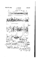
- Fig. 1 is a somewhat diagrammatic plan of the apparatus.
- Fig. 2 is a longitudinal sectional elevation to a larger scale and With a portion broken away.
- Fig. 3 is a plan of Fig. 2. f
- Fig. t is a fragmentary sectional end ele- Vation through the tracks and housings for the springs.
- Fig. 5 shews in side elevation and Fig'. G in end elevation, one formof body, simulating a racehorse With jockey, to be progressed along the tracks of the device sheWn in Figs. 1 to 4.
- Figs. 7, 8 and 9 shew similar views toFig. 5, but sheiving the body in association with the helical spring and illustrating the action of the ,engaging projections.
- Fig. 10 shevvs a modified detail hereinafter referred to.
- Figs. 11 and 12 shew in diagrammatic sectional elevation and plan a modified form of the invention hereafter referred to. n l
- Fig. 13 sheivs a cross section oic the moving bind, ⁇ such for example as sheWn in Fig. 12, and
- Fig. 14 shews another modified form of moving band in longitudinal section.
- 10 sheWs a base board which at oneend has fixed thereto a vertical stem 11 of hard steel or the like.
- a iiy-Wheel--like disc 12 On this stem 11 is mounted a iiy-Wheel--like disc 12 by means of a ballfbearing 13.
- the disc 12 is provided With manipulating handles 14, and on the underside has attached thereto a disc 15 of leather or other suitable material.
- a hollowVv compartment 16 r is formed above the base board, which is closed in by a cover plate 17, and in this compartment a rocking frame is mounted upon a horizontal axle 18.
- This rocking yframe comprises tvvo springy side members 19, an end member 20, and parallel to the said end member 20 a double member 21.
- a number of toothed pinions 22 ⁇ Which are intergeared as sheWn in Fig-3.
- Each of the spindles 23 of the pinions 22 has engaged therewith the Yhooked end 24 of a helical spring-like member 25-and it shouldk be here remarked that alternate helical spring members are of the opposite hand.
- Each helical spring 25 eX- tends into a' longitudinal housing 30 which may be of any suitable shape in cross section and has a bottom, side Walls and a top member With a central slot 31. All the housings 30 extend si de by side to the other end of the base board and the other ends of the springs are left free as sheWn in Fig. 2'and stop short just before the end of their associated housings. In desired positions across all the tracks obstacles 32 are provided. These represent ditches, Water jumps or the like and need not be slotted right through but may only be slotted in their upper portions. These are shaped as desired and in addition in some cases the tracks formed by the tops of the housings 30 may have depressions such as 33, Fig.2located in suitable position. Inv ad,-
- flaps 34 At the end of the housings 30 are mounted a number of flaps 34 having tails 35 which pass through the slots 31 into .the housings. In oneposition, that shewn Vin Fig. 2, these flaps project substantially vertically and just beyond the dead centre, and they are so disw posed that a body travelling along the track contacts with the flap and forces it over its dead centre, when it falls in the direction of the arrow 36, Fig. 2, by its weight.
- 37 is a bar hinged in bearings 38 at the endof the track and provided with two rows of teeth which come at certain angular distances apart.
- the first flap 34 is pushed over inthe direction of the arrow 36, it comes upon the lowermost teeth 39 and its weight slightly turns the toothed bar 37, to bring the next rowof teeth 40 into position to receive the next flap when it is pushed over. In this manner it is possible to determine which fiap is pushed over first as it is the flap coming be ⁇ tween the two rows of teeth 39 and 40.
- a third row of teeth may be employed to differentiate the second flap from the third and so on.
- the bodies to be caused to progress are formed as simulation racehorses and riders and are preferably made from sheet metal of desired gauge.
- the horse and jockey are represented ⁇ by 41 and this is suitably formed with or attached to the base 42 which has a slightly curved up front portion 43 and a downwardly curved portion 44 in an intermediate position.
- Beneath the base ⁇ 42 a member 45 of sheet metal is provided which may be formed in one with the body portion 41, and this member 45 has a front projection 46 and -a rear projection 47.
- ⁇ the portion 45 passes into the slot 31 and the bent portion 44 rests upon the outer surface of the top members of the cornpartments 30, which constitute a track and Y is numbered48, Fig. 6.
- the centre of gravves ity vof the parts is such that when at rest the whole device takes up the position shewn in Fig. 7, that is the forward projection 46 comes through the slot 31 and is in position to be engaged by the spring'25 as shewn in Fig. 7
- the rear projection A47 fis somewhat ⁇ hookshaped and this engagement causes the horse device to be given a certain progression. After a short period, the horse device will again rock forward to the position shewn in Fig. 7, and as a consequence a rocking and forward progression action is given by the spring alternately engaging the forward and rear projections 46 and 47. A slight amount of progression is also given to the horse device by the engagement ofthe spring with the front projectionA 46. lVhen in the forward progression the horse device comes to an obstacle, such as shewn dotted in Fig. 8, the rounded front portion of the base 43 causes the horse device to rock backwards if it was in the forward position, and this brings the rearward projection 47 into such a position that it is engaged by the rotating spring 25.
- a double friction wheel is shewn which is to replace the wheel 28.r
- This double friction wheel comprises two discs 52 and 53, the disc 52 having a roughened,serrated or toothed l that as oneof the discs, say the disc 52, comes closer to the centre of rotation of ⁇ the kflywheel-disc 12 when the toothed portion of the disc 52 is in engagement, the springs will rov tate at one speed, whilst when the teeth 53 on the other'disc are in engagement as they come further from the centre of rotation of the fly-wheel-disc 12.y the springs will then have a different speed of rotation.
- handicaps may be arranged, for example the tracks at the start may be provided as shewn in Fig. 3 with a number of markings indicating different starts for the horses and these markings may be numbered.
- An automatic handicap can be eHeoted by arranging similar numbers on the splndle ofthe wheel 12 so that this wheel can be used in conjunction with other markings on the cover plate 17, to ascertain the handicap.
- an automatic handicap may be effected by roughening or serrating certainportions of the tracks.
- certain pin head-like projections can be provided in different positions on the tracks to give the effect ofminiature jumps.
- the bases of the horses or other bodies can be formed of other shape than that shewn in the drawings. but preferably they have some form cf rocking curve included in their construction. In some cases, however, the bases may be generally flat but with a curved up front to engage with and ride over the obstacles.
- this form only one projection maybe provided forcngaging theturn of the spring or the like and this projection may be at the front and may be so formed that after it engages with the turns of the spring or the like, it is lifted or'rocked up out of engagement and falls into re-engagement.
- a second rojection maybe provided which comes into engagement with the turns of thespring or the like, when the horse or other device is tilted to overcome the obstacle.
- Figs. 11 and 12 replaces the spiral spring members and comprises an endless travelling band 60 caused to travel inr the direction of the arrow, Fig. 11, around the rollers 61.
- the upper portion. of this band is supported by a shelf or the like 62 to prevent the band sagging.
- the band On the outer surface the band is provided with a number of parallel projections 63 extending transversely across it, which projections may be formed from thin wires or the band can be provided with other rib-like projections.
- One method of arranging the wires 63 is shewn in Fig. 13 where 60is the band and 63 one of the wires, the end being bent at 64 and passed through the material of the band 60 where they are doubled back upon themselves to retain the wire in position.
- a travelling band having projections thereon, it may be formed or provided with perforations to come beneath the individual slotted tracks so that the projections on the horse or other body to be ⁇ progressed can be engaged thereby, to ⁇
- the jockey on' a horse may be made movable to alter the balance of the horse or the horse itself maybe movable on its rocker or may have a ball or other object insideit to alter the balance.
- helical spring devices may be in tension or compression and the stress may be variable to give variable results.
- the helical spring devices where used may lie on an uneven surface to cause their driving action to be somewhat capricious.
- the shape in cross section of the housing which locates the spring may vary as desired, and in preferred forms has a curved base which permits the spring to moveflaterally and to roll axially.
- the slots in the track may be ofi' the centre line and preferably are on that side to which the spring tends to roll.
- the helical member may in some cases be formed by a rigid worin or helix.
- the projections on the body which engage the helical or other springs may have any desired profile and this profile determines to a large extent the action of the body.
- the profile may be stepped so that if one portion of" the stepped profile is engaged, a-,certain action is given, whilst if another portion is engaged, asimilar action to a greater or less extent is given.
- the portion of the profile engaged may be curved or inclined in any suitable direction to give the desired cam or driving action, but in all cases it is preferable that the profile is such that there is always a tendency for ⁇ the driving projection to come free and then for another driving projection to engage the same profile, or for the body by the said freeing to bring another projection into action.
- said projections is such that will automatically cause rthe said projections to successively free themselves from the convolutions of the helical wire or spring and to reengage therewith, gear means for simultaneously rotating the plurality ofl ligure propelling means, a master gear for driving the said gear means, motor means t0 operate said master gear and clutch means for electingthe engagement and disengagement of the motor means and the master gear.
- each ofthe helical wires bar having means whereby said bar may be or springs, which constitute the figure propelling means, is located within a housing having curved lower portions which enable the springs to have lateral and rolling movements.
Landscapes
- Engineering & Computer Science (AREA)
- Multimedia (AREA)
- Toys (AREA)
- Pinball Game Machines (AREA)
Description
March 29, 1932. J. E. GRAHAM 1,851,900
GAME APPARATUS NGV. 19, 192B Till-5.1.1.
W www um as 60 63 u ,was
Patented Mar. 29, 1932 UNITED s'mrflss PATENT OFFICE j GAME APPARATUS p Application filed November 19, ,1928, Serial No. 320,506, and in Great Britain November 23, 1927.
This invention relates to game apparatus, especially racing gaine apparatus and has for its primary object to provide means for ei'- .t'ecting vthe movement or f progression of bodies, preferably competitively, it has for a further object to provide means for causing the automatic engagement and disengagement of the` said bodies from the means causing their progression, and'for a still further ob-, ject to provide means for enablingjthe lsaid bodies to move over suitable obstacles placed in their paths.
In order that the invention maybe better understood, it will now be described With ref-` erence to the accompanying drawings which shew the invention as applied to arace game apparatus, and in which Fig. 1 is a somewhat diagrammatic plan of the apparatus.
' Fig. 2 is a longitudinal sectional elevation to a larger scale and With a portion broken away. i
Fig. 3 is a plan of Fig. 2. f
Fig. t is a fragmentary sectional end ele- Vation through the tracks and housings for the springs. n
Fig. 5 shews in side elevation and Fig'. G in end elevation, one formof body, simulating a racehorse With jockey, to be progressed along the tracks of the device sheWn in Figs. 1 to 4.
Figs. 7, 8 and 9 shew similar views toFig. 5, but sheiving the body in association with the helical spring and illustrating the action of the ,engaging projections.
Fig. 10 shevvs a modified detail hereinafter referred to.
Figs. 11 and 12 shew in diagrammatic sectional elevation and plan a modified form of the invention hereafter referred to. n l
Fig. 13 sheivs a cross section oic the moving bind,` such for example as sheWn in Fig. 12, and
Fig. 14 shews another modified form of moving band in longitudinal section.
Referring to the drawings, 10 sheWs a base board which at oneend has fixed thereto a vertical stem 11 of hard steel or the like. On this stem 11 is mounted a iiy-Wheel--like disc 12 by means of a ballfbearing 13. The disc 12 is provided With manipulating handles 14, and on the underside has attached thereto a disc 15 of leather or other suitable material.
' Below and around the disc 12 a hollowVv compartment 16 ris formed above the base board, which is closed in by a cover plate 17, and in this compartment a rocking frame is mounted upon a horizontal axle 18. This rocking yframe comprises tvvo springy side members 19, an end member 20, and parallel to the said end member 20 a double member 21. Between the parts of the double member 21 are mounted a number of toothed pinions 22`Which are intergeared as sheWn in Fig-3. Each of the spindles 23 of the pinions 22 has engaged therewith the Yhooked end 24 of a helical spring-like member 25-and it shouldk be here remarked that alternate helical spring members are of the opposite hand. 28 is roughened or lightly toothed Wheel on the central spindle 23. The rocking frame mounted on the axle 18 is extended into an 'arm 29 Which comes below the Working end'of an operating lever 26. lVhen the lever is in the position shewn in Figs. 2 and 3, the rocking frame is allowed to move on its axle 18 under the action ofa fiat spring 27 bearing upon the member 20 to bring the friction Wheel 28 intov running engagement with the friction disc 15,l and When the lever 26 is in its otherl position, the rocking frame is moved to bring the parts out of running engagement, leaving the disc 12 rotating. Each helical spring 25 eX- tends into a' longitudinal housing 30 Which may be of any suitable shape in cross section and has a bottom, side Walls and a top member With a central slot 31. All the housings 30 extend si de by side to the other end of the base board and the other ends of the springs are left free as sheWn in Fig. 2'and stop short just before the end of their associated housings. In desired positions across all the tracks obstacles 32 are provided. These represent ditches, Water jumps or the like and need not be slotted right through but may only be slotted in their upper portions. These are shaped as desired and in addition in some cases the tracks formed by the tops of the housings 30 may have depressions such as 33, Fig.2located in suitable position. Inv ad,-
dition in any desired positions along the tracks small projections or depressions arranged in any given manner may also be utilized.
At the end of the housings 30 are mounted a number of flaps 34 having tails 35 which pass through the slots 31 into .the housings. In oneposition, that shewn Vin Fig. 2, these flaps project substantially vertically and just beyond the dead centre, and they are so disw posed that a body travelling along the track contacts with the flap and forces it over its dead centre, when it falls in the direction of the arrow 36, Fig. 2, by its weight. 37 is a bar hinged in bearings 38 at the endof the track and provided with two rows of teeth which come at certain angular distances apart. lhen the first flap 34 is pushed over inthe direction of the arrow 36, it comes upon the lowermost teeth 39 and its weight slightly turns the toothed bar 37, to bring the next rowof teeth 40 into position to receive the next flap when it is pushed over. In this manner it is possible to determine which fiap is pushed over first as it is the flap coming be` tween the two rows of teeth 39 and 40.
In a somewhat similar form of the device, a third row of teeth may be employed to differentiate the second flap from the third and so on.
The bodies to be caused to progress are formed as simulation racehorses and riders and are preferably made from sheet metal of desired gauge. The horse and jockey are represented `by 41 and this is suitably formed with or attached to the base 42 which has a slightly curved up front portion 43 and a downwardly curved portion 44 in an intermediate position. Beneath the base `42 a member 45 of sheet metal is provided which may be formed in one with the body portion 41, and this member 45 has a front projection 46 and -a rear projection 47.
In use., `the portion 45 passes into the slot 31 and the bent portion 44 rests upon the outer surface of the top members of the cornpartments 30, which constitute a track and Y is numbered48, Fig. 6. The centre of gravves ity vof the parts is such that when at rest the whole device takes up the position shewn in Fig. 7, that is the forward projection 46 comes through the slot 31 and is in position to be engaged by the spring'25 as shewn in Fig. 7
Supposing in this position the spring 25 were being rotated about its axis fairly rapidly, the portion of the stop 45 in contact with the spring 25 is so shaped that the parts have a cam-like action and the spring causes the horse device to be lifted up and rocked about the curved portion 44, to bring the rear projection 47 downwards through the slot 31 to :be engaged by the turns :of the :rapidly revolving spring 25.
The rear projection A47 fis somewhat {hookshaped and this engagement causes the horse device to be given a certain progression. After a short period, the horse device will again rock forward to the position shewn in Fig. 7, and as a consequence a rocking and forward progression action is given by the spring alternately engaging the forward and rear projections 46 and 47. A slight amount of progression is also given to the horse device by the engagement ofthe spring with the front projectionA 46. lVhen in the forward progression the horse device comes to an obstacle, such as shewn dotted in Fig. 8, the rounded front portion of the base 43 causes the horse device to rock backwards if it was in the forward position, and this brings the rearward projection 47 into such a position that it is engaged by the rotating spring 25. This causes the forward progres sionof the horse device and is sufiicient to lift the curved portion 4.4 from off the track 48 and by the continued action to cause the horse device to ride up the obstacle'32; the first portion of this riding up action is shewn in Fig. 9. Upon continued movement, the curve portion 44 passes over the obstacle 32 and then the horse device tilts or rocks forward, bringing the forward projection 46 into the slot 31 and in such a position that it is engaged by the rotating spring 25 and the whole device is carried forward.
In utilizing the apparatus, all the horse devices are set in the slots 31, the lever 26 is brought to the dot and dash line position (Fig. 2), and then the fiy-wheel-disc 12 is rapidly rotated. The lever 26 is now brought to the full line position and this moves the rocking frame about its axle 18 and brings the friction wheel 28 into engagement with the lever disc 15. This causes all the pinions 22 to be rapidly rotated and consequently all the springs 25 are rapidly rotated in their housings. In this position the rear portion of the horse device is slightly raised, causing the front projection 46 to come within the slot 31 and consequently when the lever 26 is pushed to the full line position, all the horses are moved forward until the cam action takes place, causing the horse to rock backwards. The race is then run in accordance with the action previouslydescribed and the first horse home makes contact with its particular flap 34, pushing this flap over, and in this position the rear projection 47 is not quite clear of the free vend of the spring i 25. Consequently the spring is given a slight compression by its continued rotation, which holds the horse against the winning post. The other horse devices which complete the course and come in after the first, also cause the associated flaps 34 to be forced over.
When the horses are moved from the slots 31 :to .be positioned ready for a further race, all the flaps 34.1nay be setback by means-of a lever handle 49, the vaxis of which also forms the pivot on which theaps are mount# ed, and this lever 49 operates another lever 50 havinganextension'l which comes behind all the flaps. This extension 51 when the lever is turned, lifts the flaps and sets them into the position shewnin Fig. 2 and then the lever is set back to its initial position, bringing the extension l to lie on a level below the pivoted bar 37 (see Fig. 2).
i' i ing over one-half its circumference.
To effect variations in the rotation of the springs, various devices may be employed, and a simple means is shewn in Fig. where a double friction wheel is shewn which is to replace the wheel 28.r This double friction wheel comprises two discs 52 and 53, the disc 52 having a roughened,serrated or toothed l that as oneof the discs, say the disc 52, comes closer to the centre of rotation of `the kflywheel-disc 12 when the toothed portion of the disc 52 is in engagement, the springs will rov tate at one speed, whilst when the teeth 53 on the other'disc are in engagement as they come further from the centre of rotation of the fly-wheel-disc 12.y the springs will then have a different speed of rotation.
It is obvious that very many modifications may be introduced into game apparatus constructed according to the invention, enabling a great variety of games to be played or for formingvarious kinds of toys in which a A body or bodies are caused to be moved.A
Ingame apparatus in accordance with `the particular discription, or with a similar game apparatus, handicaps may be arranged, for example the tracks at the start may be provided as shewn in Fig. 3 with a number of markings indicating different starts for the horses and these markings may be numbered. An automatic handicap can be eHeoted by arranging similar numbers on the splndle ofthe wheel 12 so that this wheel can be used in conjunction with other markings on the cover plate 17, to ascertain the handicap. In other cases an automatic handicap may be effected by roughening or serrating certainportions of the tracks. In this last form, certain pin head-like projections can be provided in different positions on the tracks to give the effect ofminiature jumps.
The bases of the horses or other bodies can be formed of other shape than that shewn in the drawings. but preferably they have some form cf rocking curve included in their construction. In some cases, however, the bases may be generally flat but with a curved up front to engage with and ride over the obstacles. In this form only one projection maybe provided forcngaging theturn of the spring or the like and this projection may be at the front and may be so formed that after it engages with the turns of the spring or the like, it is lifted or'rocked up out of engagement and falls into re-engagement. `With this form, however, although normally only one projection is utilized, a second rojection maybe provided which comes into engagement with the turns of thespring or the like, when the horse or other device is tilted to overcome the obstacle.
The construction shewn in Figs. 11 and 12 replaces the spiral spring members and comprises an endless travelling band 60 caused to travel inr the direction of the arrow, Fig. 11, around the rollers 61. The upper portion. of this band is supported by a shelf or the like 62 to prevent the band sagging. On the outer surface the band is provided with a number of parallel projections 63 extending transversely across it, which projections may be formed from thin wires or the band can be provided with other rib-like projections. 'Ihe upper portion of the band works beneath all the tracks that is to say is common to all the tracks, and it will be realized that the stops or the like on the horses or other objects to be progressed engage with these wires or ribs 63 to cause the yprogression of the horse or other object in an escapementlike manner.
The action is exactly similar to that with the springs, but in place of the rotation of the spring members causing the progression of the point of contact with the body to be progressed, the wires, ribs or the like travel and engage projections. l
One method of arranging the wires 63 is shewn in Fig. 13 where 60is the band and 63 one of the wires, the end being bent at 64 and passed through the material of the band 60 where they are doubled back upon themselves to retain the wire in position.
Another construction would be such as Ythat shewn in Fig. 14 which shews a portion of the longitudinal section of the band formed or provided Iwith transverse rib-like members 65. I
In some cases in place of a travelling band having projections thereon, it may be formed or provided with perforations to come beneath the individual slotted tracks so that the projections on the horse or other body to be `progressed can be engaged thereby, to`
cause the progression in arocking and escaperment-like manner.
with respect to another portion. In one such constructionk the jockey on' a horse may be made movable to alter the balance of the horse or the horse itself maybe movable on its rocker or may have a ball or other object insideit to alter the balance.
In some cases,'where helical spring devices are employed, they may be in tension or compression and the stress may be variable to give variable results.
A The helical spring devices where used may lie on an uneven surface to cause their driving action to be somewhat capricious.
The shape in cross section of the housing which locates the spring may vary as desired, and in preferred forms has a curved base which permits the spring to moveflaterally and to roll axially. In some cases the slots in the track may be ofi' the centre line and preferably are on that side to which the spring tends to roll.
The helical member may in some cases be formed by a rigid worin or helix.
The projections on the body which engage the helical or other springs may have any desired profile and this profile determines to a large extent the action of the body. In some cases the profile may be stepped so that if one portion of" the stepped profile is engaged, a-,certain action is given, whilst if another portion is engaged, asimilar action to a greater or less extent is given. In other cases the portion of the profile engaged may be curved or inclined in any suitable direction to give the desired cam or driving action, but in all cases it is preferable that the profile is such that there is always a tendency for` the driving projection to come free and then for another driving projection to engage the same profile, or for the body by the said freeing to bring another projection into action.
The invention is not limited to the precise forms or details of construction described as these may be varied to suit particular cases.
What I claim and desire to secure by Letters Patent of the United States of America is z-f j l. Racing game apparatus comprising a fixed track, a figure adapted for movement upon the fixed track, the said figure being itself entirely supported by said lixed track, figure propelling means consisting of a helical wire or spring, motor means for operating the said gure propelling means, depending spaced projections carried by the figure, the said projections being adapted to detachably engage with the convolutions of the helical wire or spring to effect the progression of the figure upon the fixed track, Vwhile the shape, form and disposition of the said projections is such that will automatically cause the said projections to successively free themselves from the convolul tions of the helical wire 0r spring and to re- Leblanc engage therewith for the `punoses set farth- 2- Racine seme apparatus .Comprising e fixed track, a plurality of figures adapted for movement, uren the fixed treek, @ech 0f the said igures being itself entirely supported bythe said fixed track, a plurality of ligure propelling means each consisting of ay .helical wire or spring, depending spaced projections carried by each of the figures, the 4said projections being adapted to detachably engage with the convolutions of the associated helical Vwire or springto effect the progression of the associated figure upon the fixed track, while the shape, form and disposition of the. said projections is such that will automatically cause rthe said projections to successively free themselves from the convolutions of the helical wire or spring and to reengage therewith, gear means for simultaneously rotating the plurality ofl ligure propelling means, a master gear for driving the said gear means, motor means t0 operate said master gear and clutch means for electingthe engagement and disengagement of the motor means and the master gear.`
3. Racing vgame apparatus according to claim 2, wherein the motor means comprises a revoluble iiy-wheellike elementwhich is adapted to drive the master gear by fric- 9 tional engagement therewith for the purpose of driving the plurality of figure propelling means and wherein is provided =means for moving the master gear into and out of engagement with the revoluble flywheel-like element for the purpose of stopping or starting the plurality of figure propelling means when desired.
4. Racing game apparatus accordingto claim 2, wherein means are providedy for automatically indicating the figure finishing first, the said means comprising a tiltable member in the course of each figure land a so moved by the first tiltable member reached by a racing figure as to designate such racing figure.
5. Racing game apparatus according to claim 2, wherein each ofthe helical wires bar having means whereby said bar may be or springs, which constitute the figure propelling means, is located within a housing having curved lower portions which enable the springs to have lateral and rolling movements. i
In witness whereof I aiiix my signature.
JOHN nLPHiNsToNE GRAHAM.
Applications Claiming Priority (3)
| Application Number | Priority Date | Filing Date | Title |
|---|---|---|---|
| CA303743T | |||
| GB1851900X | 1927-11-23 | ||
| GB31554/27A GB311828A (en) | 1927-11-23 | 1927-11-23 | Improvements in and relating to game apparatus |
Publications (1)
| Publication Number | Publication Date |
|---|---|
| US1851900A true US1851900A (en) | 1932-03-29 |
Family
ID=58661346
Family Applications (1)
| Application Number | Title | Priority Date | Filing Date |
|---|---|---|---|
| US320506A Expired - Lifetime US1851900A (en) | 1927-11-23 | 1928-11-19 | Game apparatus |
Country Status (3)
| Country | Link |
|---|---|
| US (1) | US1851900A (en) |
| CA (1) | CA303743A (en) |
| GB (1) | GB311828A (en) |
Cited By (2)
| Publication number | Priority date | Publication date | Assignee | Title |
|---|---|---|---|---|
| US2643885A (en) * | 1950-04-03 | 1953-06-30 | William C Ford | Racing apparatus |
| US3473805A (en) * | 1965-02-04 | 1969-10-21 | Hans Biller | Endless coil spring operated racing game |
-
0
- CA CA303743A patent/CA303743A/en not_active Expired
-
1927
- 1927-11-23 GB GB31554/27A patent/GB311828A/en not_active Expired
-
1928
- 1928-11-19 US US320506A patent/US1851900A/en not_active Expired - Lifetime
Cited By (2)
| Publication number | Priority date | Publication date | Assignee | Title |
|---|---|---|---|---|
| US2643885A (en) * | 1950-04-03 | 1953-06-30 | William C Ford | Racing apparatus |
| US3473805A (en) * | 1965-02-04 | 1969-10-21 | Hans Biller | Endless coil spring operated racing game |
Also Published As
| Publication number | Publication date |
|---|---|
| GB311828A (en) | 1929-05-23 |
| CA303743A (en) | 1930-09-09 |
Similar Documents
| Publication | Publication Date | Title |
|---|---|---|
| US1992085A (en) | Method of dealing playing cards | |
| US2838870A (en) | Marble runway game | |
| US1879511A (en) | Mechanically operated game table | |
| US2123195A (en) | Game apparatus | |
| US3951412A (en) | Horse racing board game apparatus | |
| US1851900A (en) | Game apparatus | |
| US2180448A (en) | Amusement device | |
| US4010956A (en) | Drag racing game apparatus | |
| US1454173A (en) | Gaming appliance | |
| US3462148A (en) | Game board and vehicle with vehicle trapping means | |
| US3954268A (en) | Drag racing game apparatus | |
| US1511497A (en) | Toy | |
| US1634194A (en) | Educational toy | |
| US1553909A (en) | Mechanical racing toy | |
| US3190652A (en) | Racing game apparatus | |
| US1502183A (en) | Game | |
| US2591956A (en) | Ball-actuated racing game device | |
| US3129941A (en) | Racing game apparatus | |
| US3735984A (en) | Racetrack amusement device | |
| US1399582A (en) | Amusement device | |
| US1730523A (en) | Game | |
| US1654991A (en) | Puzzle or toy | |
| US1154988A (en) | Card-shuffler. | |
| US1560277A (en) | Apparatus for playing race games | |
| US1531401A (en) | Game |