US1851895A - Silk-recorder - Google Patents
Silk-recorder Download PDFInfo
- Publication number
- US1851895A US1851895A US294018A US29401828A US1851895A US 1851895 A US1851895 A US 1851895A US 294018 A US294018 A US 294018A US 29401828 A US29401828 A US 29401828A US 1851895 A US1851895 A US 1851895A
- Authority
- US
- United States
- Prior art keywords
- thread
- pulleys
- lever
- silk
- pulley
- Prior art date
- Legal status (The legal status is an assumption and is not a legal conclusion. Google has not performed a legal analysis and makes no representation as to the accuracy of the status listed.)
- Expired - Lifetime
Links
- 230000033001 locomotion Effects 0.000 description 22
- 238000004804 winding Methods 0.000 description 7
- 238000000034 method Methods 0.000 description 4
- 230000001105 regulatory effect Effects 0.000 description 4
- 238000006243 chemical reaction Methods 0.000 description 3
- 239000000835 fiber Substances 0.000 description 3
- 238000004519 manufacturing process Methods 0.000 description 2
- 230000010355 oscillation Effects 0.000 description 2
- 238000005096 rolling process Methods 0.000 description 2
- 238000000926 separation method Methods 0.000 description 2
- 229920002955 Art silk Polymers 0.000 description 1
- 229910001369 Brass Inorganic materials 0.000 description 1
- LUTSRLYCMSCGCS-BWOMAWGNSA-N [(3s,8r,9s,10r,13s)-10,13-dimethyl-17-oxo-1,2,3,4,7,8,9,11,12,16-decahydrocyclopenta[a]phenanthren-3-yl] acetate Chemical compound C([C@@H]12)C[C@]3(C)C(=O)CC=C3[C@@H]1CC=C1[C@]2(C)CC[C@H](OC(=O)C)C1 LUTSRLYCMSCGCS-BWOMAWGNSA-N 0.000 description 1
- 239000010951 brass Substances 0.000 description 1
- 238000005520 cutting process Methods 0.000 description 1
- 238000006073 displacement reaction Methods 0.000 description 1
- 230000003534 oscillatory effect Effects 0.000 description 1
- 229920000136 polysorbate Polymers 0.000 description 1
- 238000003825 pressing Methods 0.000 description 1
- 230000000750 progressive effect Effects 0.000 description 1
- 229910010271 silicon carbide Inorganic materials 0.000 description 1
Images
Classifications
-
- G—PHYSICS
- G01—MEASURING; TESTING
- G01N—INVESTIGATING OR ANALYSING MATERIALS BY DETERMINING THEIR CHEMICAL OR PHYSICAL PROPERTIES
- G01N3/00—Investigating strength properties of solid materials by application of mechanical stress
- G01N3/08—Investigating strength properties of solid materials by application of mechanical stress by applying steady tensile or compressive forces
-
- G—PHYSICS
- G01—MEASURING; TESTING
- G01N—INVESTIGATING OR ANALYSING MATERIALS BY DETERMINING THEIR CHEMICAL OR PHYSICAL PROPERTIES
- G01N2203/00—Investigating strength properties of solid materials by application of mechanical stress
- G01N2203/02—Details not specific for a particular testing method
- G01N2203/026—Specifications of the specimen
- G01N2203/0262—Shape of the specimen
- G01N2203/0278—Thin specimens
- G01N2203/028—One dimensional, e.g. filaments, wires, ropes or cables
Definitions
- silk-recorders In the silk industry instruments are regularly used called silk-recorders, of which the purpose is to indicate the reaction produced on a thread when it is stretched a certain amount.
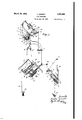
- Fig. 1 is a dia ammatic perspective view of such a self-registering silk-recorder.
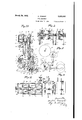
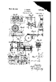
- Figs. 2-14 are actual detailed views of the different finished sections.
- Fig. 15 is a perspective view of the whole.
- rollers 0, a, 0 which can, under the action of a lever d, be raised, and in front of these drums are placed two pulleys e and 6 each with four grooves and mounted freely on their shaft in a support f,
- crank lever h pivoted on a point i move parallel to it.
- The. recording system proper iscomposed of a pendulum j, which, carrying two small pulleys lc and k is connected with a system Z, oscillating on a fixed axis m.
- This system includes, in its pivoting: an arm n, at the end of which is fixed a needle 0, supported on a cylinder p covered with a band of paper,
- the cylinder p is actuated by a slow rotary movement around its axis by the principal shaft a, with which it is connected by a train of gears not shown in the -draw-' ings.
- the shaft '1) of the aforesaid cylinder 32 moves the crank lever h, by means of a cam w (see Fig. 7) a wheel a: mounted on a bar 3 controlled by a .spring 2 and by a rod 2.
- the system of rolling the thread on a bobbin 3 is worked by a hollow shaft 4 on which itis fixed and on which moves freely a pulley 5 controlled by 6. Moreover, a piece 7, fixed on the shaft 4 as regards the rotary movement, but which can move paral-' lel to its own axis, is constantly moved along against the aforementioned pulley 5, by means of a rod 8 crossing the hollow shaft 4 bin 17, passes through the guide-14 and then over the drum 6 of smallest diameter.
- the oil dashpot u prevents displacements of the needle arising from vibrations in the instrumentorfromaccidentalcauses.
- the instrument Invarying the position of the counter-weight g by the aid of the screw 1',- the instrument is regulated for all qualities of silk, whatever their elasticity.
- support f of the pulleys e and e is actuated, by the recording cylinder p, in an alternative movement (arrows 18) so .as th prevent the thread of silk from passing always in the same place on the drums b, 6 b and thus from cutting the rubber.
- the drums b, b and b of Fig. 1 may be formed in two parts 20 and 21 which are fixed on the axis a by means of a screw-nut 22 (Fig. 2).
- This method of mounting allows the adjustment of the drums on the axis even after they have once been mounted, which assures a perfectly even turning and thus overcomes one of the causes of the breaking of the thread.
- the fixing of the rubber is assured by three movable plates 23, 24 and 25, which press it against the ends of the drums. These plates are controlled by bolts 26 which cross the drum 21 and are supported on the inside of the drum 20. In screwing these bolts one presses the rubber 51, which is thus fixed at one end and in the middle.
- the last plate 25 is controlled by a nut 27, screwed on the end of the axis a. This serves, at the same time, to conceal the placement of the screws.
- the drum can be modified by doing away with the rubber which wears much too rapidly.
- the pulleys 0, 0 and c intended to support the thread of silk on the rubber so as to prevent all slipping, must be independent of each other, in such a way that the pressure will be constant, and they must be easily removed, for the fluff from the silk lodges there and prevents the instrument from working.
- the pulley 0 is mounted in the same way with a separate counter-weight. It is therefore completely independent of the first.
- Pulley 0 is supported by a single red 38,
- This pulley can be removed elsewhere when the pulley c is raised by simply unscrewing the loose screw-nut 42 which locks its roller bearing on the tube 39.
- the lever of the rheostat for starting and regulating is mounted on the same axis as the control of the movement of the pulleys which must be separated from the drum every time the instrument is stopped in order that the thread can be placed in.
- lever 43 controls the rheostat by means of an axis 44. (Fig. 5.)
- This axis has three small forks, each with a little pulley 45. These pulleys are supported on the end of the levers 35 and tend to raise them. In moving the lever in the direction of the arrow, it is seen that the three counterweights are raised, that, on the contrary, the three pulleys are lowered and the progressive movement of the motor is stopped.
- the three counter-weights 37 which place the three pulleys against the drum are set free at the same time as the motor is set in motion. Following up this movement, a time comes, when the three pulleys c, 0 and 0 are in contact with the drum, when the small pulleys 45 leave the lever. The working of the lever can then be continued to increase the speed, but it is seen that at this moment the levers and the pulleys pressure on the i are now submitted only to the action of their respective counter-weights.
- thread must be moved. It has been judged preferable not to move the thread during the course of the trial. which might harm the precision. It is sufficient to move it a certain amount every time a trial is completed.
- a movable deadener 57 running on the axis 54 and driven by it by means of a key 58 can be supported with a variable pressure against the stopper 55. It results from this that the stopper and the nucleus which are interdependent, are driven with a force which depends on that which acts on the movable deadener 57.
- This deadener is controlled by the thread itself which passes over a pulley 59 (Figs. 13 and 14) and tends to lower it, exerting thus a certain traction on a rod 60, which is provided at its lower end with a counter-weight 61 and with a small screw 62 (Figs. 8 and 9).
- the tension 'of the thread of silk is thus communicated successively to the rod 60, to the screw 62, and to a crank lever 63 which carries the pulleys 64, which act in their turn on the deadener 57, tending thus to remove it from the nucleus carrying the bobbin.
- the instrument can be used to determine the type of silk, that is to say, the weight of IIJ a 'ven length of thread. In this case, it is s cient to take a bobbin, take the weiglitof it, place it on the instrument, roll on it a known length of silk and weight it.
- a disc 70 whose movement arises from that of the drum by means of an endless screw, is divided into a certain number of equal parts, which forms a certain number of notches.
- a system'of two' levers 71 and 72 is supported, on the circumference of this disc.
- the lever 71 carries a pulley 73 and a boss 74. which serves to fix precisely the stopping point of the machine.
- This lever is supported against the disc by the spring 75.
- the lever 72 rests on the lever 71 for it is driven by the spring 52.
- This lever carries, isolated by a fibre plate,.a contact screw 76 which rests permanently against the screw 77 of the first lever, which closes the circuit of the motor.
- the, disc turns, the pulley 73 and the boss 7 4*follow the notches, the lever 71 moves, but the lever 72 will move along with it, and there is no breakage in the contact of the screws 76 and 7 7 and, consequently, no stopping. of the motor.
- the instrument includes a handle 78, moving on an axis 79 (Fig. 12) whose extremity 80 crosses the supporting plate and can hold up the end 81 of the lever 72. It is seen that, if the handle 78 is lowered, the lever 71 will follow the notches of the disc 70, but that, each time the lever 71 falls in the hollow of a notch, the lever 72 being held up separated, the two screws 76 and 77 will be separated and, consequently, therewill be a stoppage of the instrument. The spacofthread on the bobbin.
- V of increasing diameter in combination with loose pulleys having grooves on their periphcry for engagement by the thread and to permit movement of the thread longitudinally of said loose pulleys, a support on which the loose pulleys are mounted, means for imparting a to and fro movement to the support and means to record variations in the tension of the thread.
- thread engaging rollers of increasing diameter in combination with loose pulleys with grooves on their periphery for engagement by the thread and to permit movement of the thread longitudinally of said loose pulleys, a support on which the loose pulleys are mounted, means for impart ing a to andv fro movement to the support,
- winding bobbin means to rotate the same, and means to regulate the rotation of the winding bobbin to cause the same to regulate the tension of the thread during the passage of the thread from the tensioning means to the winding bobbin and means to record variations in the tension of the thread.
- thread tensioning apparatus of the type referred to in which the thread is given "a constant stretching, thread engaging rollers "of increasing diameter in combination with loose pulleys having groves ontheir periphcry for engagement by the thread and to permit movement of the thread longitudinally ing of the notches will be regulated so that at each stoppage there will be the desired length of said loose pulleys, a support on which the loose pulleys are mounted, means for imparting a to and fro movement to the support, an oscillating device actuatedby variations in the tension of the thread under tension, a winding bobbin, means to rotate the same and means to regulate the rotation of the winding bobbin to cause the same to regulate the tension of the thread during the passage of the thread from the tensioning means to the winding bobbin and means to record variations in the tension of the thread.
- a plurality of tensioning drums means to rotate the same, a plurality of pulleys arranged opposite the tensionin drums, pressure rollers for movement to and means to record the variations in the tension of the thread.
Landscapes
- Physics & Mathematics (AREA)
- Health & Medical Sciences (AREA)
- Life Sciences & Earth Sciences (AREA)
- Chemical & Material Sciences (AREA)
- Analytical Chemistry (AREA)
- Biochemistry (AREA)
- General Health & Medical Sciences (AREA)
- General Physics & Mathematics (AREA)
- Immunology (AREA)
- Pathology (AREA)
- Tension Adjustment In Filamentary Materials (AREA)
Description
March 29, 1932. Q CORNET 1,851,895
SILK RECORDER Filed July 19. 1928 3 Sheets-Sheet 1 SILK RECORDER Filed July 19, 1928' 3 Sheets-Sheet 2 March 29, 1932'.
CORNET 1,851,895
SILK RECORDER Filed July 19, 1928 3 Sheets-Sheet 3 Patented Mar. 29, 1932.
UNITED STATES PATENT OFFICE ANDRE connnr, or LYON, FRANCE SILK-RECORDER Application fi led July 19, 1928, Serial No. 294,018, and in France July 29, 1927.
In the silk industry instruments are regularly used called silk-recorders, of which the purpose is to indicate the reaction produced on a thread when it is stretched a certain amount.
Among these instruments, there are some which register automatically, in a continuous manner, on a band of paper, the variations in thickness of a thread of silk.
Actually, if a thread of silk is taken and an attempt is made to stretch it a certain amount, it is necessary to exert on this thread a certain tension, which will be greater as the thread is thicker, and inversely, will be less according as the thread is finer. On the other hand, it is recognized that, for slight stretchings and for silks of the same type and origin, this tension is practically proportional to the thickness of the thread of silk.
The principle on which these instruments are based is, therefore, to exert on a thread, which is moving, a constant stretching, sufficiently weak not to destroy the law of proportion mentioned above and to register, automatically on a band of paper, the variations in the reaction produced on this thread by the stretching to which it is submitted, a reaction which is equal and in the opposite sense to the tension.
39 In instruments of this kind, numerous improvements to which it is the object of the present invention to bring about, the stretching of the thread is effected by rolling it on drums of increasing diameter.
number of members which can be taken sep- 'arately or preferably in combination, with a view to obtaining a continuous self-registering silk-recorder which functions absolutely 40 perfectly.
It consists essentially in certain improvements applied to the system of stretching the thread as much as to the method of graphic registering.
It consists also, besides these main dispositions, in other different dispositions to be used, preferably, at the same time, and these will be explained more clearly hereafter.
It will be possible to understand it, with The present invention has for its object a.
the aid of the followin drawings given by way 0 example Fig. 1 is a dia ammatic perspective view of such a self-registering silk-recorder.
Figs. 2-14 are actual detailed views of the different finished sections.
Fig. 15 is a perspective view of the whole.
In Fig. l on a shaft (1, connected directly and receiving a rotary movement from the motor, are fixed three drums b, b 6 of increasing diameters, which are all three covered with rubber.
On these drums bear rollers 0, a, 0 which can, under the action of a lever d, be raised, and in front of these drums are placed two pulleys e and 6 each with four grooves and mounted freely on their shaft in a support f,
description and which, constantly moved by a spring 9, can,
by means of a crank lever h pivoted on a point i move parallel to it.
The. recording system proper iscomposed of a pendulum j, which, carrying two small pulleys lc and k is connected with a system Z, oscillating on a fixed axis m. This system includes, in its pivoting: an arm n, at the end of which is fixed a needle 0, supported on a cylinder p covered with a band of paper,
a counter-weight q, able, with the aid of a screw, to be approached to and withdrawn from the centre of oscillation, in moving before a graduated scale s, the rod t of an oil dash pot u.
Moreover, the cylinder p is actuated by a slow rotary movement around its axis by the principal shaft a, with which it is connected by a train of gears not shown in the -draw-' ings.
The shaft '1) of the aforesaid cylinder 32, moves the crank lever h, by means of a cam w (see Fig. 7) a wheel a: mounted on a bar 3 controlled by a .spring 2 and by a rod 2.
The system of rolling the thread on a bobbin 3 is worked by a hollow shaft 4 on which itis fixed and on which moves freely a pulley 5 controlled by 6. Moreover, a piece 7, fixed on the shaft 4 as regards the rotary movement, but which can move paral-' lel to its own axis, is constantly moved along against the aforementioned pulley 5, by means of a rod 8 crossing the hollow shaft 4 bin 17, passes through the guide-14 and then over the drum 6 of smallest diameter. It
next passes over the first groove of the pulley e returns round the second drum 1), of
slightly greater diameter than the former, on
which it makes three turns and passes each time over one of the grooves of pulley 6. From there, it passes over. the pulleys k and k of the pendulum j of the, recording I system, and re-descends over the third drum 6 of a slightly greater diameter than 6 It then makes four turns on this drum and passes each time over one of the grooves of the pulley c then passes, between the guide pulleys 12 and 13, over pulley 11 of the oscillatory system, from where, finally, it arrives at the bobbin 3.
Because of the covering of rubber on the drums b, 12 b which prevents slipping, and of the pressing cylinders 2, 0, 0 the thread 16, being thus forced to take the same movement as the circumference of the aforesaid drums, which becomes greater and greater in passing from the first tothe last, is thus tween the pieces'7 and 5 and so modifying the V stretched a certain amount which is always constant.
This stretching, resulting from the variations in thickrfess of the thread, produces a tension more or less great on the pendulum j which oscillates on the axis m and marks these oscillations on the cylinder p actuated by a rotary movement on its axis 2) proportional to the speed of rotation of the shafta, and therefore to the lineal speed of the thread 16.
The oil dashpot u prevents displacements of the needle arising from vibrations in the instrumentorfromaccidentalcauses. Invarying the position of the counter-weight g by the aid of the screw 1',- the instrument is regulated for all qualities of silk, whatever their elasticity. I
Moreover, support f of the pulleys e and e is actuated, by the recording cylinder p, in an alternative movement (arrows 18) so .as th prevent the thread of silk from passing always in the same place on the drums b, 6 b and thus from cutting the rubber.
Then the thread, in pulling more or less on the pulley 11, tends to raise this in making the system 9 swing on its fixed axis 19, modifying in the same proportion the pressure heforce of the impulse of the bobbin 3.
With regard to the actual manufacture of the instrument,
fied, of such an instrument, one can set about it as follows, or ina similar manner:
The drums b, b and b of Fig. 1 may be formed in two parts 20 and 21 which are fixed on the axis a by means of a screw-nut 22 (Fig. 2). This method of mounting allows the adjustment of the drums on the axis even after they have once been mounted, which assures a perfectly even turning and thus overcomes one of the causes of the breaking of the thread.
The fixing of the rubber is assured by three movable plates 23, 24 and 25, which press it against the ends of the drums. These plates are controlled by bolts 26 which cross the drum 21 and are supported on the inside of the drum 20. In screwing these bolts one presses the rubber 51, which is thus fixed at one end and in the middle. The last plate 25 is controlled by a nut 27, screwed on the end of the axis a. This serves, at the same time, to conceal the placement of the screws.
- This arrangement is very suitable for the trial of natural silks of a certain fineness.
For thicker silks and for artificial silks, the drum can be modified by doing away with the rubber which wears much too rapidly.
In this case, the brass drums covered with rubber are replaced by cylinders of carborundum of very fine grain, made exactly to the desired diameter. These are, then, the pulleys in Fig. 4 which are covered with rubber.
The pulleys 0, 0 and c intended to support the thread of silk on the rubber so as to prevent all slipping, must be independent of each other, in such a way that the pressure will be constant, and they must be easily removed, for the fluff from the silk lodges there and prevents the instrument from working.
They are mounted each on a single roller bearing (Fig. 4) These bearings are mount-.
ed on tubes such as 28. The separation is effected by the sleeve tubes 29, which block the to communicate to them the movement of the lever 35 swivelled at the point 36 andhaving the counter-weight 37, giving a constant pressure.
The pulley 0 is mounted in the same way with a separate counter-weight. It is therefore completely independent of the first.
Pulley 0 is supported by a single red 38,
which carries a tube 39, allowing to pass, with a certain play, the pin of the pulley 0 and its tube of separation. The rod-38 being mounted on the same axis as the rods 40 and 41, it is seen that the pulley 0 can move some millimeters with regard to pulley 0 As it has also a third counter-weight, it is seen that it will be completely independent of the pulley o and that the drum 5 is thus constant. I
This pulley can be removed elsewhere when the pulley c is raised by simply unscrewing the loose screw-nut 42 which locks its roller bearing on the tube 39.
To simplify the workingof the instrument, the lever of the rheostat for starting and regulating is mounted on the same axis as the control of the movement of the pulleys which must be separated from the drum every time the instrument is stopped in order that the thread can be placed in.
For this purpose, the lever 43 controls the rheostat by means of an axis 44. (Fig. 5.)
This axis has three small forks, each with a little pulley 45. These pulleys are supported on the end of the levers 35 and tend to raise them. In moving the lever in the direction of the arrow, it is seen that the three counterweights are raised, that, on the contrary, the three pulleys are lowered and the progressive movement of the motor is stopped.
By acting in the opposite way, the three counter-weights 37 which place the three pulleys against the drum are set free at the same time as the motor is set in motion. Following up this movement, a time comes, when the three pulleys c, 0 and 0 are in contact with the drum, when the small pulleys 45 leave the lever. The working of the lever can then be continued to increase the speed, but it is seen that at this moment the levers and the pulleys pressure on the i are now submitted only to the action of their respective counter-weights.
To prevent the thread from always travel ling on the same point on the rubber and in order not to cut the rubber very quickly, the
thread must be moved. It has been judged preferable not to move the thread during the course of the trial. which might harm the precision. It is sufficient to move it a certain amount every time a trial is completed.
To obtain this result (Fig. 6) the side of the recording drum p, placed vertically, bears a cam at a certain point. On this side is supported a small pulley 46 fixed at the end of a lever held by a spring. This lever, in moving, makes to move, by means of a ratchet 47, a toothed wheel 48 which is connected with an eccentric 49. At each turn of the recording drum, it is seen that the toothed wheel moves forward a few-teeth. This movement of the eccentric moves slightly the lever 50 which is connected by diverse levers and axes to the support of the guide pulleys of the thread. At each turn of the drum, the thread is therefore moved a certain amount and does not be submitted to a constant tension, for variations in the tension can lessen the adherence of the thread on the rubber and, consequently,
instantly to clean it and to remove the fiufi'.
The force of the nucleus, and therefore the tension of the thread, are assured by friction. A movable deadener 57, running on the axis 54 and driven by it by means of a key 58 can be supported with a variable pressure against the stopper 55. It results from this that the stopper and the nucleus which are interdependent, are driven with a force which depends on that which acts on the movable deadener 57.
This deadener is controlled by the thread itself which passes over a pulley 59 (Figs. 13 and 14) and tends to lower it, exerting thus a certain traction on a rod 60, which is provided at its lower end with a counter-weight 61 and with a small screw 62 (Figs. 8 and 9). The tension 'of the thread of silk is thus communicated successively to the rod 60, to the screw 62, and to a crank lever 63 which carries the pulleys 64, which act in their turn on the deadener 57, tending thus to remove it from the nucleus carrying the bobbin.
It is thus seen that, if the tension of the thread increases for any cause whatever, the deadener is brought back behind, lessening thus the pressure with which it rests on the fibre stopper 55 which lessens the tension by lessening the speed of rotation of the winding up bobbin 3 by reducing the friction of the element 55 thereagainst. There is therefore an automatic regulation of the thread. To arrive at a greater precision, another system has been added (Fig. 10) which consists of a cylinder 65, carrying an arm 66 which can rest, with a variable pressure, against the axis of the aforesaid pulley 64. This pressure is obtained by a spiral screw 67 which is inside the cylinder and is fixed at the other end on a loose cap 68 which can easily be moved by hand. In turningthis cap, it is seen that the screw can be made to move with more or less force on the cylinder, and, consequently, to produce an eflort more or less great on the lever 66, and to rest more or less, by means of the pulleys 64, the deadener 57 against the fibre disc 55, and there is thus a means of regulating precisely the tension of the thread of silk. A damper 69 (Fig. 9) regulates the movements of the pulleys 64. l
The instrument can be used to determine the type of silk, that is to say, the weight of IIJ a 'ven length of thread. In this case, it is s cient to take a bobbin, take the weiglitof it, place it on the instrument, roll on it a known length of silk and weight it.
It is necessary therefore to arrange a method by which the instrument stops automatically when a certain length of thread has passed through it. It is just as desirable as making it go without stopping automatically.
With this object, recourse is had to the following system (Fig. 11 and 12).
A disc 70, whose movement arises from that of the drum by means of an endless screw, is divided into a certain number of equal parts, which forms a certain number of notches.
A system'of two' levers 71 and 72 is supported, on the circumference of this disc. The lever 71 carries a pulley 73 and a boss 74. which serves to fix precisely the stopping point of the machine. This lever is supported against the disc by the spring 75.
Mounted on the same axis 82, the lever 72 rests on the lever 71 for it is driven by the spring 52. This lever carries, isolated by a fibre plate,.a contact screw 76 which rests permanently against the screw 77 of the first lever, which closes the circuit of the motor. When the instrument is working, the, disc turns, the pulley 73 and the boss 7 4*follow the notches, the lever 71 moves, but the lever 72 will move along with it, and there is no breakage in the contact of the screws 76 and 7 7 and, consequently, no stopping. of the motor.
But the instrument includes a handle 78, moving on an axis 79 (Fig. 12) whose extremity 80 crosses the supporting plate and can hold up the end 81 of the lever 72. It is seen that, if the handle 78 is lowered, the lever 71 will follow the notches of the disc 70, but that, each time the lever 71 falls in the hollow of a notch, the lever 72 being held up separated, the two screws 76 and 77 will be separated and, consequently, therewill be a stoppage of the instrument. The spacofthread on the bobbin.
It 'is evident and follows from what precedes that the invention is not at all limited to the single method of manufacture men-- all the variations in execution based on the same working principle. J
V of increasing diameter in combination with loose pulleys having grooves on their periphcry for engagement by the thread and to permit movement of the thread longitudinally of said loose pulleys, a support on which the loose pulleys are mounted, means for imparting a to and fro movement to the support and means to record variations in the tension of the thread.
2. In thread-tensioning apparatus of the type referred to in which the thread is given a constant stretching, thread engaging rollers of increasing diameter in combination with loose pulleys with grooves on their periphery for engagement by the thread and to permit movement of the thread longitudinally of said loose pulleys, a support on which the loose pulleys are mounted, means for impart ing a to andv fro movement to the support,
an oscillating device'actuated by variation in to and fro movement to the support, an oscillating device actuated by variation in the tension of the thread under tension, :1. winding bobbin, means to rotate the same, and means to regulate the rotation of the winding bobbin to cause the same to regulate the tension of the thread during the passage of the thread from the tensioning means to the winding bobbin and means to record variations in the tension of the thread.
4. In thread tensioning apparatus of the type referred to in which the thread is given "a constant stretching, thread engaging rollers "of increasing diameter in combination with loose pulleys having groves ontheir periphcry for engagement by the thread and to permit movement of the thread longitudinally ing of the notches will be regulated so that at each stoppage there will be the desired length of said loose pulleys, a support on which the loose pulleys are mounted, means for imparting a to and fro movement to the support, an oscillating device actuatedby variations in the tension of the thread under tension, a winding bobbin, means to rotate the same and means to regulate the rotation of the winding bobbin to cause the same to regulate the tension of the thread during the passage of the thread from the tensioning means to the winding bobbin and means to record variations in the tension of the thread..
5. In threadtensioning apparatus of the class described, a plurality of tensioning drums, means to rotate the same, a plurality of pulleys arranged opposite the tensionin drums, pressure rollers for movement to and means to record the variations in the tension of the thread.
In Witness whereof I afiix my signature.
ANDRE CORNET.
Applications Claiming Priority (1)
| Application Number | Priority Date | Filing Date | Title |
|---|---|---|---|
| FR1851895X | 1927-07-29 |
Publications (1)
| Publication Number | Publication Date |
|---|---|
| US1851895A true US1851895A (en) | 1932-03-29 |
Family
ID=9681666
Family Applications (1)
| Application Number | Title | Priority Date | Filing Date |
|---|---|---|---|
| US294018A Expired - Lifetime US1851895A (en) | 1927-07-29 | 1928-07-19 | Silk-recorder |
Country Status (1)
| Country | Link |
|---|---|
| US (1) | US1851895A (en) |
Cited By (15)
| Publication number | Priority date | Publication date | Assignee | Title |
|---|---|---|---|---|
| US2632325A (en) * | 1950-06-01 | 1953-03-24 | Austin S Norcross | Yarn-testing apparatus |
| US2634607A (en) * | 1946-08-09 | 1953-04-14 | Lawson Products Inc | Strand testing machine |
| US3590632A (en) * | 1967-11-23 | 1971-07-06 | Zellweger Uster Ag | Process for measuring the strength and elongation of a continuously travelling thread |
| US3881346A (en) * | 1972-10-24 | 1975-05-06 | Leonische Drahtwerke Ag | Process for measuring the modulus of elasticity |
| US3933035A (en) * | 1973-09-19 | 1976-01-20 | J. Bobst & Fils S.A. | Installation for continuous measurement of the elastic coefficient of a traveling strip, wire or ribbon |
| US20050167460A1 (en) * | 2004-02-04 | 2005-08-04 | The Procter & Gamble Company | Method of controlling tension in a moving web material |
| US20050166670A1 (en) * | 2004-02-04 | 2005-08-04 | The Procter & Gamble Company | Method of determining a modulus of elasticity of a moving web material |
| US7552649B1 (en) * | 2008-07-29 | 2009-06-30 | Cheng Uei Precision Industry Co., Ltd. | Cable testing device |
| US8733686B2 (en) | 2010-10-25 | 2014-05-27 | The Procter & Gamble Company | Alternative apparatus for reducing web feed rate variations induced by parent roll geometry variations |
| US8733687B2 (en) | 2010-10-25 | 2014-05-27 | The Procter & Gamble Company | Alternative apparatus for reducing web feed rate variations induced by parent roll geometry variations |
| US8733685B2 (en) | 2010-10-25 | 2014-05-27 | The Procter & Gamble Company | Apparatus for reducing web feed rate variations induced by parent roll geometry variations |
| US8740130B2 (en) | 2010-10-25 | 2014-06-03 | The Procter & Gamble Company | Alternative method for reducing web feed rate variations induced by parent roll geometry variations |
| US8757535B2 (en) | 2010-10-25 | 2014-06-24 | The Procter & Gamble Company | Method for reducing web feed rate variations induced by parent roll geometry variations |
| US9434572B2 (en) | 2010-10-25 | 2016-09-06 | The Procter & Gamble Company | Alternative method for reducing web feed rate variations induced by parent roll geometry variations |
| US9434573B2 (en) | 2010-10-25 | 2016-09-06 | The Procter & Gamble Company | Alternative method for reducing web feed rate variations induced by parent roll geometry variations |
-
1928
- 1928-07-19 US US294018A patent/US1851895A/en not_active Expired - Lifetime
Cited By (17)
| Publication number | Priority date | Publication date | Assignee | Title |
|---|---|---|---|---|
| US2634607A (en) * | 1946-08-09 | 1953-04-14 | Lawson Products Inc | Strand testing machine |
| US2632325A (en) * | 1950-06-01 | 1953-03-24 | Austin S Norcross | Yarn-testing apparatus |
| US3590632A (en) * | 1967-11-23 | 1971-07-06 | Zellweger Uster Ag | Process for measuring the strength and elongation of a continuously travelling thread |
| US3881346A (en) * | 1972-10-24 | 1975-05-06 | Leonische Drahtwerke Ag | Process for measuring the modulus of elasticity |
| US3933035A (en) * | 1973-09-19 | 1976-01-20 | J. Bobst & Fils S.A. | Installation for continuous measurement of the elastic coefficient of a traveling strip, wire or ribbon |
| US6993964B2 (en) | 2004-02-04 | 2006-02-07 | The Procter & Gamble Company | Method of determining a modulus of elasticity of a moving web material |
| US20050166670A1 (en) * | 2004-02-04 | 2005-08-04 | The Procter & Gamble Company | Method of determining a modulus of elasticity of a moving web material |
| US6991144B2 (en) | 2004-02-04 | 2006-01-31 | The Procter & Gamble Company | Method of controlling tension in a moving web material |
| US20050167460A1 (en) * | 2004-02-04 | 2005-08-04 | The Procter & Gamble Company | Method of controlling tension in a moving web material |
| US7552649B1 (en) * | 2008-07-29 | 2009-06-30 | Cheng Uei Precision Industry Co., Ltd. | Cable testing device |
| US8733686B2 (en) | 2010-10-25 | 2014-05-27 | The Procter & Gamble Company | Alternative apparatus for reducing web feed rate variations induced by parent roll geometry variations |
| US8733687B2 (en) | 2010-10-25 | 2014-05-27 | The Procter & Gamble Company | Alternative apparatus for reducing web feed rate variations induced by parent roll geometry variations |
| US8733685B2 (en) | 2010-10-25 | 2014-05-27 | The Procter & Gamble Company | Apparatus for reducing web feed rate variations induced by parent roll geometry variations |
| US8740130B2 (en) | 2010-10-25 | 2014-06-03 | The Procter & Gamble Company | Alternative method for reducing web feed rate variations induced by parent roll geometry variations |
| US8757535B2 (en) | 2010-10-25 | 2014-06-24 | The Procter & Gamble Company | Method for reducing web feed rate variations induced by parent roll geometry variations |
| US9434572B2 (en) | 2010-10-25 | 2016-09-06 | The Procter & Gamble Company | Alternative method for reducing web feed rate variations induced by parent roll geometry variations |
| US9434573B2 (en) | 2010-10-25 | 2016-09-06 | The Procter & Gamble Company | Alternative method for reducing web feed rate variations induced by parent roll geometry variations |
Similar Documents
| Publication | Publication Date | Title |
|---|---|---|
| US1851895A (en) | Silk-recorder | |
| US2811012A (en) | Plying apparatus and method | |
| GB711501A (en) | Improvements in apparatus for detecting and correcting irregularities of thickness ofa textile sliver | |
| US2018971A (en) | Machine for testing threads | |
| US2920345A (en) | Method and apparatus for producing variable denier yarn | |
| US2650414A (en) | Control device | |
| CN215517993U (en) | Front yarn dividing area tension control system of sizing machine | |
| US2323991A (en) | Yarn twisting | |
| US2996870A (en) | Winding tension control mechanism | |
| GB841255A (en) | Improvements in or relating to textile testing apparatus | |
| SU12051A1 (en) | Drive in rayon spinning machine | |
| US2093820A (en) | Cross winding frame for winding strand materials | |
| US2303903A (en) | Knitting machine | |
| US707684A (en) | Winding-machine. | |
| US3042330A (en) | Balling head | |
| SU38959A1 (en) | A device for imparting shine to curled cellulose fibers | |
| US3274824A (en) | Method and apparatus for tensile testing | |
| US1858205A (en) | Double twist flyer spinning machine | |
| US1630426A (en) | Slub catcher | |
| US3303534A (en) | Double apron drafting system for drawing frames | |
| SU990901A1 (en) | V-belt speed-varying gear of warp feed motion in loom | |
| US2374832A (en) | Roving frame | |
| GB407342A (en) | Improvements in or relating to yarn warping or beaming apparatus | |
| US1503441A (en) | Traverse mechanism | |
| US2670148A (en) | Quick-traverse mechanism for winding machines |