US1851855A - Broiler - Google Patents
Broiler Download PDFInfo
- Publication number
- US1851855A US1851855A US354778A US35477829A US1851855A US 1851855 A US1851855 A US 1851855A US 354778 A US354778 A US 354778A US 35477829 A US35477829 A US 35477829A US 1851855 A US1851855 A US 1851855A
- Authority
- US
- United States
- Prior art keywords
- compartment
- housing
- base
- rollers
- tracks
- Prior art date
- Legal status (The legal status is an assumption and is not a legal conclusion. Google has not performed a legal analysis and makes no representation as to the accuracy of the status listed.)
- Expired - Lifetime
Links
- 241000287828 Gallus gallus Species 0.000 title description 16
- 238000010411 cooking Methods 0.000 description 10
- 238000010276 construction Methods 0.000 description 7
- 230000000295 complement effect Effects 0.000 description 2
- 230000005484 gravity Effects 0.000 description 2
- 239000000725 suspension Substances 0.000 description 2
- 241001137251 Corvidae Species 0.000 description 1
- AYFVYJQAPQTCCC-GBXIJSLDSA-N L-threonine Chemical compound C[C@@H](O)[C@H](N)C(O)=O AYFVYJQAPQTCCC-GBXIJSLDSA-N 0.000 description 1
- 208000027418 Wounds and injury Diseases 0.000 description 1
- 238000013459 approach Methods 0.000 description 1
- 230000006378 damage Effects 0.000 description 1
- 230000001066 destructive effect Effects 0.000 description 1
- 235000013305 food Nutrition 0.000 description 1
- 208000014674 injury Diseases 0.000 description 1
- 238000012986 modification Methods 0.000 description 1
- 230000004048 modification Effects 0.000 description 1
- 235000015108 pies Nutrition 0.000 description 1
- 230000002787 reinforcement Effects 0.000 description 1
- 230000000630 rising effect Effects 0.000 description 1
- 238000007665 sagging Methods 0.000 description 1
- 238000007789 sealing Methods 0.000 description 1
Images

Classifications
-
- F—MECHANICAL ENGINEERING; LIGHTING; HEATING; WEAPONS; BLASTING
- F24—HEATING; RANGES; VENTILATING
- F24C—DOMESTIC STOVES OR RANGES ; DETAILS OF DOMESTIC STOVES OR RANGES, OF GENERAL APPLICATION
- F24C15/00—Details
- F24C15/16—Shelves, racks or trays inside ovens; Supports therefor
- F24C15/162—Co-operating with a door, e.g. operated by the door
Definitions
- a still further object is to provide a construction of the aforementioned type having novel anti-friction and alignment means, as
- .Which I Fig. 1 is a phantom perspective view of a portion of, a cooking range, illustrating one broiler housing tracks;
- Fig. i is a side elevation of the broiler compartment
- Fig. 7 is a front vertical view of the device illustrated in Fig. 1, taken on a line across the face of the housing, the drawer being illustrated in section;
- Fig. 8 is a view similar to Fig. 4 showing the contour. of the track in section.
- the improvements have been illustrated in position beneath an oven of a gas or electric range but it is understood may be variously embodied in 12, sides 13 and 14, back 15, front 16, and base or bottom 17.
- the front 16 hasan opening 18 defined by ofi'set flange 19 surrounding sald opening.
- the oven 10 and housing 11 are supported by frame members 20 and these members in turn may be suppor d in any convenient manner on the range.
- This guide means 21 extending from the front to the rear thereof-and positioned substantially 1 centrally of the base. This guide means comprlses a plurality of spaced tracks 22 and-23,
- the base 17 of housing 11 is provided with whichnas seen in Fig.2 have flanges 24 for securing the tracks to the base.
- Each track 7 a has a vertical wall rising from flange 24 and terminates inan' inwardly extending flan e 25.
- a U-shaped reinforcement plate 39 is st-antially in alignment (transversely of the base 17) with rollers 27, 28, and the forward end of guide means 21.
- the broiler compartment 30 comprises a drawer shaped member having sides 31, 32, back 33, bottom 34 and an open top and front bolted, welded or otherwise secured about the forward open end of the compartment and thereby braces and holds sides 31, 32 and bottom 34 in proper position and insures against distortion of or injury to the compartment.
- This plate as well as the sides of the compartment are slot-ted to receive the hinge pins of door 35.
- This door is accordingly hinged to open downwardly about a horizontal axis to give the user access to the interior of the compartment and a view thereof without drawing the compartment completely from the housing.
- Stop means for holding the door in horizontal position are also provided as illustrated in Fig. 1.
- the door 35 When closed, as seen in Fig. 4', the door 35, held by latch 36 and pin 37, forms the front end of the compartment. .Further details of the door and hinge arrangement may be had upon reference to our copending application filed August 21, 1928, Serial No.
- a broiler pan (not shown) is adapted to seaton ledges 38 provided on each side of the compartment and may be removed and replaced at different levels by simply unlatching the door and placing it in open position (Fig. 1). P
- the bottom 34 of. the drawer or compartment 30 is provided with tracks 40 and 41. As illustrated, these tracks are mounted adjacent the side edges of the drawer or'compartment and are formed with grooves which serve as guide means for the drawer or compartment in which rollers 27 and 28 are adapted to ride. Upon reference to Fig. 4, it is notable that the forward end of each track is provided with a depression or recess 42 (see Fig. 4).
- Rollers 43 and 44 are also provided on the bottom of the compartment and are positioned substantially centrally of the rear end thereof.
- a guide member 45 is located near said rollers and projects downwardly from the bottom 34.
- Stop means 46 also protrude from the compartment bottom and are positioned so as to be in alignment with stops 29 on the housing base, when the compartment is within the housing.
- the rollers 27, 28, on the housing base are disposed in the grooves of tracks 40 and 41 of the compartment.
- the rollers 43 and 44 of the compartment are disposed in the channel 26 defined by the tracks 22 and 23 on the base of the housing.
- rollers 27 and 28 are disposed out of alignment with rollers '43 and 44.
- This arrangement affords a sturdy construction for supporting the broiler compartment during all its movements and also in all positions in which it may come to rest.
- the compartment 30 is thus afforded support at a plurality of spaced bearing points oflset from one another so that sliding movement is facilitated. Accordingly the weight of the compartment is uniformly distributed and the compartment is'maintained substantially level or on an even keel since it is supported at all times atthree spaced points, which points define the apices of an imaginary triangle. Obviously, therefore, twisting of the compartment and consequent sticking or binding is eliminated.
- the guide means 45 projects downwardly and rides between the edges of flanges 25 of tracks 22 and 23. Accordingly, the compartment is held in proper alignment and is prevented from sidewise movement about its own vertical axis.
- rollers 43 and 44 permits'them to ride beneath and in alignment' with the overhanging flanges of tracks 22 and-23. Accordingly, these members c ooperate to retain the compartment level and to prevent sagging of the forward portion when that portion is protruding (as in Fig.
- rollers 43, 44 and mounting thereof are deslgned to afford a nice fit in channel 26 therecompartment and housing.
- the guide means in the present improvements are in alignment with the force of gravity, so that there is no tendency to wrench said means from their mountings, 3
- the present improvements have been illustrated and described in their application to a broiler construction, but it is understood tha't the'improvements are not. limited. thereto.
- The-invention is: equally baking or cooking compartments, Accord ⁇ ingly, the novel arrangement may be applied j to oven pans or any elementadapted to support food, such asbread, cakes, pies, etc.,
- the guide or track means may be formed, if desired, in the j 1. ha cooking range, a housing having aroller mounted on the base thereof, a cooking drawendlsposed in said housing and having .a' track and spaced rollers mounted on the bottom of the drawer, said first named roller cooperating with said track and said spaced rollers being mounted centrally of the drawer I and adapted to engage the base of the housing.
- a broiler housing a 1 I broiler drawer disposed therein and adapted for sliding movement with respect to said housing.
- said drawer having a track mounted on thebase thereof and said housing having a complementary roller mounted on the base.
- said track having a recess therein adapted to receive a portion of said roller for releasably 0 locking said-drawer in position.
- a cooking drawer having a base, sides and open top, members forming spaced grooves provided along the base of the drawer,- a roller mounted onsaid base and between said-grooves, said roller being dis- 'mo' posed adjacent one end of said base.
- a cooking drawer having a base, sides grooves provided along the base of the drawer, a roller mounted onsaid'base and between said grooves, said roller being disposed adjacent one end of saidbase and a hinged door defining the forward side of said drawer.
- a range construction having a three point supporting arrangement comprising a housin having mounted on the base a cenall mounted on-the bottom of said drawer,
- rollers and tracks cooperating with one another respectively, means forlimiting the outward movement of said drawer, said tracks, rollers and limiting means being con-- structed and arranged whereby complete re-; moval of the drawer from the housing is afforded 6.
- a range construction having a three point suspension arrangement comprising a housing, a drawer disposed therein, one of said elements having on the base thereof a substantially centrally disposed track and roller members on each side. of said track, the other element havinga substantially centrally disposed roller and tracks on each side thereof all mounted on the base of said other element one of said tracks forming a channel with the base on which it is mounted and one of said rollers disposed under said track and within said channel, said rollers and tracks of the respective elements cooperating with one another for facilitating sliding movement of said drawer.
- a range construction having a thre point suspension arrangement comprising a housing, a'drawer disposed therein, the base of each element respectively having tracks and rollers alternately disposed therealong with the rollers mounted adjacent the -ends oftheir respectivdbases, at least one roller -.of the arrangement being disposed substantially centrally of the housing and drawer, one of said tracks forming a channel with the base on which it is mounted and one, of
- rollers disposed under said track and within said channel.
- a housing having an open front, spaced rollers mounted on the base of the housing adjacent the front 'corv ners thereof, spaced tracks mounted on the base of the housing substantially 'centrally thereof, abroiler drawer disposed in said housing and movable through the open front, said drawer having spaced tracks on the base thereof engagingthe aformentioned rollers, and additional iollers mounted on the rear portion of the base of the drawer adjacent the center thereof and engaging thev tracks of the housing.
- a broiler housing having on its base a substantially centrally disposed trackway, sai'l trackway comprising laterally extending tracks defining an open top'channel, a broiler drawer in said housing having rollers projecting from the base thereof into said channel and engaging the under. side of the laterally extending tracks.
Landscapes
- Engineering & Computer Science (AREA)
- Chemical & Material Sciences (AREA)
- Combustion & Propulsion (AREA)
- Mechanical Engineering (AREA)
- General Engineering & Computer Science (AREA)
- Drawers Of Furniture (AREA)
Description
Mamh 1932- A. J. LINDEMANN ET AL 1,351,855
BROILEIIR Filed April 15, 1929 3 Sheets-Sheet l i I i l l March 29, 1932. J UNDEMANN ET AL 1,851,855
BROILER Filed April 13, 1929 3 Sheets-Sheet 2 March 1932- A. .1. LINDEMANN ET AL v 1,851,355
BROILER Filed April 15. 1929 SSheets-Sheet 3e Patented Man-29, 1932 UNITED STATES PATENT orrlcr.
ALBERT J. LINDEMANN,' WALTEB C. LINDEMANN, AND ADOLPH '1. SCHMIDT, OF MIL- WAUKEE, WISCONSIN,,ASSIGNORS TO A. J'- LINDEMANN & HOVERSON COMPANY, OF MILWAUKEE, WISCONSIN, A CORPORATION OF WISCONSIN ZBBOILEB Application filed s in 1s,
' The improvements relate to cooking ranges and more particularly to compartments to be "used in connection with gas ovens and ranges,
, pearance, readily slidable in or removable from the stove.
A still further object is to provide a construction of the aforementioned type having novel anti-friction and alignment means, as
well as an improvedmanner of slidably supporting the compartment. In. accordance improvements to embody thatprinciple in a novel range'construction thereby-insuring,
at all times, theproper support of movable compartments without twisting or strailr thereof. 7
Other objects and advantages of the present improvements will be apparent to those skilled in the art upon reference to the-acflcompanying specification and drawings, in
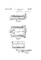
.Which I Fig. 1 is a phantom perspective view of a portion of, a cooking range, illustrating one broiler housing tracks;
Fig. i is a side elevation of the broiler compartment;
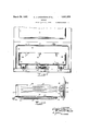
- 4 Fig. 5 is a bottom plan view of the broiler compartment Fig. 7 is a front vertical view of the device illustrated in Fig. 1, taken on a line across the face of the housing, the drawer being illustrated in section;
Fig. 8 is a view similar to Fig. 4 showing the contour. of the track in section.
1929. Serial 110. 354,778.
. In the drawings, the improvements have been illustrated in position beneath an oven of a gas or electric range but it is understood may be variously embodied in 12, sides 13 and 14, back 15, front 16, and base or bottom 17. The front 16 hasan opening 18 defined by ofi'set flange 19 surrounding sald opening. The oven 10 and housing 11 are supported by frame members 20 and these members in turn may be suppor d in any convenient manner on the range.
guide means 21 extending from the front to the rear thereof-and positioned substantially 1 centrally of the base. This guide means comprlses a plurality of spaced tracks 22 and-23,
The base 17 of housing 11 is provided with whichnas seen in Fig.2 have flanges 24 for securing the tracks to the base. Each track 7 a has a vertical wall rising from flange 24 and terminates inan' inwardly extending flan e 25. As positioned on base 17,"these trac s form with the base, a channel or groove 26,
' lengthwise of the housing, said channel hav-.
ing an open portion extending the length thereof, due to the spacing of the tracks. 7
Upon reference to Figs. 1 and 3, it is seen that. the tracks 22 and 23 flare or diverge ad-.
vjatent each end and terminate short of-the front and rear of the housing. Thevflared front portion bfth'e. guide means 21 thereby as hereinafter described.
near the front of the compartment,'one on each side of guidejmeans'21 and betweenit and thesides of the housing. Protruding upwardlv from the base of the housing, are
. a plurality of stop means 29, which are subafi'ords an entrance means to the channel 26,
end. A U-shaped reinforcement plate 39 is st-antially in alignment (transversely of the base 17) with rollers 27, 28, and the forward end of guide means 21.
The broiler compartment 30 comprises a drawer shaped member having sides 31, 32, back 33, bottom 34 and an open top and front bolted, welded or otherwise secured about the forward open end of the compartment and thereby braces and holds sides 31, 32 and bottom 34 in proper position and insures against distortion of or injury to the compartment. This plate as well as the sides of the compartment are slot-ted to receive the hinge pins of door 35. This door is accordingly hinged to open downwardly about a horizontal axis to give the user access to the interior of the compartment and a view thereof without drawing the compartment completely from the housing.
Stop means for holding the door in horizontal position are also provided as illustrated in Fig. 1. When closed, as seen in Fig. 4', the door 35, held by latch 36 and pin 37, forms the front end of the compartment. .Further details of the door and hinge arrangement may be had upon reference to our copending application filed August 21, 1928, Serial No.
301,060. A broiler pan (not shown) is adapted to seaton ledges 38 provided on each side of the compartment and may be removed and replaced at different levels by simply unlatching the door and placing it in open position (Fig. 1). P
The bottom 34 of. the drawer or compartment 30 is provided with tracks 40 and 41. As illustrated, these tracks are mounted adjacent the side edges of the drawer or'compartment and are formed with grooves which serve as guide means for the drawer or compartment in which rollers 27 and 28 are adapted to ride. Upon reference to Fig. 4, it is notable that the forward end of each track is provided with a depression or recess 42 (see Fig. 4).
When the compartment 30 is assembled in the housing 11, the rollers 27, 28, on the housing base, are disposed in the grooves of tracks 40 and 41 of the compartment. Likewise, the rollers 43 and 44 of the compartment are disposed in the channel 26 defined by the tracks 22 and 23 on the base of the housing. 'It is notable that all the rollers project a slight distance from the plane of their mountings whereby the compartment bottom is suspendfree sliding movement of the compartment is afforded by the cooperating rollers and guides. Accordingly the opposed faces of the housing and compartment are spaced so that friction is reduced to a minimum and wear of the parts is restricted to the tracks of each.
Free sliding movement of the compartment is thereby afforded, outwardmovement thereof being limited by the contact of cooperative stop means 29 and 46. It is important to note that the'compartment 30 is somewhat smaller than housing 11 and occupies only the lower portion thereof. However, door 35 is much larger than the open end of compartment 30, andserves to close the opening 18 of the housing.
As the compartment .is moved inwardly and approaches the complete closed position the rollers 27,28 of the housing enter recesses 42 of the tracks 40 and 41, thereby causing the compartment to slide home into closed position with the door 35 sealing the housing opening 18 by engaging flange 19. These depressions or recesses 1n the tracks which are occupied by the rollers, as described, serve to releasa ly hold the compartment in closed position.
Upon reference to Fi 1, it is seen that the rollers 27 and 28 are disposed out of alignment with rollers '43 and 44. This arrangement affords a sturdy construction for supporting the broiler compartment during all its movements and also in all positions in which it may come to rest. The compartment 30 is thus afforded support at a plurality of spaced bearing points oflset from one another so that sliding movement is facilitated. Accordingly the weight of the compartment is uniformly distributed and the compartment is'maintained substantially level or on an even keel since it is supported at all times atthree spaced points, which points define the apices of an imaginary triangle. Obviously, therefore, twisting of the compartment and consequent sticking or binding is eliminated.
While the cooperating guides and rollers prevent lateral movement of the compartment. with respect to the housing, i. e., a wabbling movement, the guide means 45 projects downwardly and rides between the edges of flanges 25 of tracks 22 and 23. Accordingly, the compartment is held in proper alignment and is prevented from sidewise movement about its own vertical axis.
Should it'be found desirable to completely .sertion of the compartment may be accomplished in a similar manner. The diverging tcompartment in closed position is of marked entrant portion of guide means 21, facilitates these operationaslnce rollers 43, 44 are afforded" more;
The novel arrangement of rollers 43 and 44 permits'them to ride beneath and in alignment' with the overhanging flanges of tracks 22 and-23. Accordingly, these members c ooperate to retain the compartment level and to prevent sagging of the forward portion when that portion is protruding (as in Fig.
1) and the center of gravity of the compartment is in advance of rollers 27and 28. The
The advantages of the present improvements cannot be overemphasized. Since the weight of the broilervcompartment and its anti-friction rollers are disposed solely on the i destructive effectv of the traveling compa'rt- Jme'nt to the tracks, does not exert; a-strain tending to'loosen the tracks.
bottom of thehousing and compartment, where they oppose and. carry the weight superposed thereon. Obviously, nosagging of the base of the compartment is possible, as is i the case when broilers are supported by means on the side walls thereof, a j
Furthermore, the guide means in the present improvements are in alignment with the force of gravity, so that there is no tendency to wrench said means from their mountings, 3
and open top,. members forming spaced as is frequently the situation wherev such means extend laterally from the sidewalls of the broiler compartment or housing. Accordingly, the constant weight as well as the The novel means for. releasably holding the adyanta e. The slight inclination of the f: 'tracks- 40, and 41, defining recesses 42 in which ..the'rollers 27, 28-may'rest,serves to hold the compartment in sealed condition- This tea-- ture tends to conserve heat, and is of distinct advantage to the housewife since she is assured, when closing the compartment, that it will remain closed.
As aforementioned, the present improvements have been illustrated and described in their application to a broiler construction, but it is understood tha't the'improvements are not. limited. thereto. The-invention is: equally baking or cooking compartments, Accord} ingly, the novel arrangement may be applied j to oven pans or any elementadapted to suport food, such asbread, cakes, pies, etc.,
wherein it is desirable towholly or partially pace for entry to and withbv insuring against looseness between the apphcable W n tructions and-other Qrmer remove .or insert same, into or from the heatlng area for lnspectlon or for other reasons.
Various modifications within the-scope of the improvements will be apparent to those skilled in the art. Forexample, the guide or track means may be formed, if desired, in the j 1. ha cooking range, a housing having aroller mounted on the base thereof, a cooking drawendlsposed in said housing and having .a' track and spaced rollers mounted on the bottom of the drawer, said first named roller cooperating with said track and said spaced rollers being mounted centrally of the drawer I and adapted to engage the base of the housing.
2. In a cooking range, a broiler housing, a 1 I broiler drawer disposed therein and adapted for sliding movement with respect to said housing. said drawer having a track mounted on thebase thereof and said housing having a complementary roller mounted on the base.
thereof and adapted to travel in said track, said track having a recess therein adapted to receive a portion of said roller for releasably 0 locking said-drawer in position.
3. A cooking drawer having a base, sides and open top, members forming spaced grooves provided along the base of the drawer,- a roller mounted onsaid base and between said-grooves, said roller being dis- 'mo' posed adjacent one end of said base.
4. A cooking drawer having a base, sides grooves provided along the base of the drawer, a roller mounted onsaid'base and between said grooves, said roller being disposed adjacent one end of saidbase and a hinged door defining the forward side of said drawer.
'5. A range construction having a three point supporting arrangement comprising a housin having mounted on the base a cenall mounted on-the bottom of said drawer,
said rollers and tracks cooperating with one another respectively, means forlimiting the outward movement of said drawer, said tracks, rollers and limiting means being con-- structed and arranged whereby complete re-; moval of the drawer from the housing is afforded 6. In a cooking range, a housing, a drawer by slight upward canting of the] disposed'therein and adapted for sliding movement with respect tosaid housing, one of said members having an angular :track member projecting laterally and defining with the'base thereof a laterally accessible 7 ehannel and the other member having a complementary roller projecting laterally into and disposed within said channel and adapted to engage a wall thereof.
7. A range construction having a three point suspension arrangement comprising a housing, a drawer disposed therein, one of said elements having on the base thereof a substantially centrally disposed track and roller members on each side. of said track, the other element havinga substantially centrally disposed roller and tracks on each side thereof all mounted on the base of said other element one of said tracks forming a channel with the base on which it is mounted and one of said rollers disposed under said track and within said channel, said rollers and tracks of the respective elements cooperating with one another for facilitating sliding movement of said drawer.
8. A range construction having a thre point suspension arrangement comprising a housing, a'drawer disposed therein, the base of each element respectively having tracks and rollers alternately disposed therealong with the rollers mounted adjacent the -ends oftheir respectivdbases, at least one roller -.of the arrangement being disposed substantially centrally of the housing and drawer, one of said tracks forming a channel with the base on which it is mounted and one, of
said rollers disposed under said track and within said channel.
,9. In a cooking range, a housing having an open front, spaced rollers mounted on the base of the housing adjacent the front 'corv ners thereof, spaced tracks mounted on the base of the housing substantially 'centrally thereof, abroiler drawer disposed in said housing and movable through the open front, said drawer having spaced tracks on the base thereof engagingthe aformentioned rollers, and additional iollers mounted on the rear portion of the base of the drawer adjacent the center thereof and engaging thev tracks of the housing.
10. A broiler housing having on its base a substantially centrally disposed trackway, sai'l trackway comprising laterally extending tracks defining an open top'channel, a broiler drawer in said housing having rollers projecting from the base thereof into said channel and engaging the under. side of the laterally extending tracks.
Witness our hands this 8th day of April,
SHI.
ALBERT J. LINDEMANN. WALTER o. LINDEMANN. 'ADOLPH rsoHMIDn 1929, county of Milwaukee, State of Wiscon- I
Priority Applications (1)
| Application Number | Priority Date | Filing Date | Title |
|---|---|---|---|
| US354778A US1851855A (en) | 1929-04-13 | 1929-04-13 | Broiler |
Applications Claiming Priority (1)
| Application Number | Priority Date | Filing Date | Title |
|---|---|---|---|
| US354778A US1851855A (en) | 1929-04-13 | 1929-04-13 | Broiler |
Publications (1)
| Publication Number | Publication Date |
|---|---|
| US1851855A true US1851855A (en) | 1932-03-29 |
Family
ID=23394870
Family Applications (1)
| Application Number | Title | Priority Date | Filing Date |
|---|---|---|---|
| US354778A Expired - Lifetime US1851855A (en) | 1929-04-13 | 1929-04-13 | Broiler |
Country Status (1)
| Country | Link |
|---|---|
| US (1) | US1851855A (en) |
Cited By (14)
| Publication number | Priority date | Publication date | Assignee | Title |
|---|---|---|---|---|
| US2461902A (en) * | 1946-01-10 | 1949-02-15 | Caloric Gas Stove Works | Detachable oven door |
| US2477853A (en) * | 1949-08-02 | Accessible quick freeze drawer | ||
| US2587691A (en) * | 1946-09-20 | 1952-03-04 | Wilbur A Brewer | Drawer construction |
| US2630000A (en) * | 1948-10-19 | 1953-03-03 | Breckenridge Frank | Retractable washer in cabinet |
| US2668092A (en) * | 1950-08-31 | 1954-02-02 | Gen Electric | Mounting arrangement for storage receptacles |
| US2672384A (en) * | 1950-02-01 | 1954-03-16 | Russell T Richards | Fold-away cabinet table |
| US2778911A (en) * | 1952-08-12 | 1957-01-22 | Gen Motors Corp | Domestic appliance |
| US2880716A (en) * | 1956-01-16 | 1959-04-07 | Dixie Products Inc | Cooking range |
| US3139313A (en) * | 1961-03-14 | 1964-06-30 | I Xl Furniture Company Inc | Self-closing drawer |
| US4318575A (en) * | 1981-01-02 | 1982-03-09 | Eagle Sheet Metal Mfg. Company | Mobile file cabinet with drawer stabilizing wheel support means |
| US4892368A (en) * | 1988-10-03 | 1990-01-09 | Malgo Corporation | Drawer slide |
| US20090085366A1 (en) * | 2007-10-01 | 2009-04-02 | Toyota Motor Engineering & Manufacturing North America, Inc. | Device Holder And Storage Drawer |
| US20120153791A1 (en) * | 2010-12-16 | 2012-06-21 | Bush Industries, Inc. | Drop Front Locking Device and Hinge |
| US11199331B2 (en) | 2019-10-10 | 2021-12-14 | Electrolux Home Products, Inc. | Cooking oven with cavity drawer having movable door |
-
1929
- 1929-04-13 US US354778A patent/US1851855A/en not_active Expired - Lifetime
Cited By (15)
| Publication number | Priority date | Publication date | Assignee | Title |
|---|---|---|---|---|
| US2477853A (en) * | 1949-08-02 | Accessible quick freeze drawer | ||
| US2461902A (en) * | 1946-01-10 | 1949-02-15 | Caloric Gas Stove Works | Detachable oven door |
| US2587691A (en) * | 1946-09-20 | 1952-03-04 | Wilbur A Brewer | Drawer construction |
| US2630000A (en) * | 1948-10-19 | 1953-03-03 | Breckenridge Frank | Retractable washer in cabinet |
| US2672384A (en) * | 1950-02-01 | 1954-03-16 | Russell T Richards | Fold-away cabinet table |
| US2668092A (en) * | 1950-08-31 | 1954-02-02 | Gen Electric | Mounting arrangement for storage receptacles |
| US2778911A (en) * | 1952-08-12 | 1957-01-22 | Gen Motors Corp | Domestic appliance |
| US2880716A (en) * | 1956-01-16 | 1959-04-07 | Dixie Products Inc | Cooking range |
| US3139313A (en) * | 1961-03-14 | 1964-06-30 | I Xl Furniture Company Inc | Self-closing drawer |
| US4318575A (en) * | 1981-01-02 | 1982-03-09 | Eagle Sheet Metal Mfg. Company | Mobile file cabinet with drawer stabilizing wheel support means |
| US4892368A (en) * | 1988-10-03 | 1990-01-09 | Malgo Corporation | Drawer slide |
| US20090085366A1 (en) * | 2007-10-01 | 2009-04-02 | Toyota Motor Engineering & Manufacturing North America, Inc. | Device Holder And Storage Drawer |
| US7708328B2 (en) * | 2007-10-01 | 2010-05-04 | Toyota Motor Engineering & Manufacturing North America, Inc. | Device holder and storage drawer |
| US20120153791A1 (en) * | 2010-12-16 | 2012-06-21 | Bush Industries, Inc. | Drop Front Locking Device and Hinge |
| US11199331B2 (en) | 2019-10-10 | 2021-12-14 | Electrolux Home Products, Inc. | Cooking oven with cavity drawer having movable door |
Similar Documents
| Publication | Publication Date | Title |
|---|---|---|
| US1851855A (en) | Broiler | |
| US3806987A (en) | Barbecue hinge structure | |
| US3122134A (en) | Gas heated oven construction | |
| US3161755A (en) | Cooking range | |
| US2746448A (en) | Oven | |
| EP1532403B1 (en) | Shelf arrangement for ovens | |
| US1954580A (en) | Gas stove | |
| US1851854A (en) | Broiler | |
| US2649085A (en) | Broiler door and rack | |
| US2088957A (en) | Stove and range | |
| US2682263A (en) | Range broiler | |
| ATE16559T1 (en) | ELECTRIC BAKING AND FRYING DEVICE SUCH AS A GRILL OR WAFFLE IRON. | |
| US20210381695A1 (en) | Baking oven | |
| US2804027A (en) | Semi-permanent pullman covers for baking ovens and automatic lifting means therefor | |
| US2180161A (en) | Elevatable stove oven | |
| US1341829A (en) | Oven | |
| US2657110A (en) | Broiler structure | |
| US2070049A (en) | Tray moving device for ovens | |
| US2753236A (en) | Cabinet and sliding doors therefor | |
| US1944061A (en) | Oven door | |
| US2560959A (en) | Cooking stove | |
| US1961332A (en) | Cooking stove or range | |
| US1891118A (en) | Range | |
| US1710433A (en) | Attachment for gas ranges | |
| US1416478A (en) | Range |