US1851849A - Still for separating absorption oil from gasoline - Google Patents
Still for separating absorption oil from gasoline Download PDFInfo
- Publication number
- US1851849A US1851849A US409920A US40992029A US1851849A US 1851849 A US1851849 A US 1851849A US 409920 A US409920 A US 409920A US 40992029 A US40992029 A US 40992029A US 1851849 A US1851849 A US 1851849A
- Authority
- US
- United States
- Prior art keywords
- unit
- tank
- oil
- absorption oil
- gasoline
- Prior art date
- Legal status (The legal status is an assumption and is not a legal conclusion. Google has not performed a legal analysis and makes no representation as to the accuracy of the status listed.)
- Expired - Lifetime
Links
Images

Classifications
-
- C—CHEMISTRY; METALLURGY
- C10—PETROLEUM, GAS OR COKE INDUSTRIES; TECHNICAL GASES CONTAINING CARBON MONOXIDE; FUELS; LUBRICANTS; PEAT
- C10G—CRACKING HYDROCARBON OILS; PRODUCTION OF LIQUID HYDROCARBON MIXTURES, e.g. BY DESTRUCTIVE HYDROGENATION, OLIGOMERISATION, POLYMERISATION; RECOVERY OF HYDROCARBON OILS FROM OIL-SHALE, OIL-SAND, OR GASES; REFINING MIXTURES MAINLY CONSISTING OF HYDROCARBONS; REFORMING OF NAPHTHA; MINERAL WAXES
- C10G7/00—Distillation of hydrocarbon oils
Definitions
- This invention relates to a distillation unit associated with an absorber system.
- An object of the invention is the provision of a distillation unit connected with I3 an absorber system for removing the light hydrocarbons, suchas gasoline, from a saturated absorption oil which has passed through various steps of treatment before entering the evaporation or distillationunit.
- Another object of the invention is the provision of a distillation unit in which thesaturated absorption oil must pass through a tortuous path of an auxiliary heat unit for progressively vaporizinghigh test gasoline from the absorption oil which is collected in a chamber at the bottonrof the still, superheated steam being applied directly to the surface of the collected absorption oil for creating a vapor tension thereon with a consequent evaporation of any high test gasoline in the oil, the superheated steam being conducted through the perforated bubble trays for agitating the absorption oil moving over said trays and in close association with the heating unit.
- sorber and distillation unit constructed in :acE j cordance 1 with the principles "my: ,iI, 1 v,e I1 tion, i a F gur 2 is a ver cal se fii oi; h 'd llatiOn 11n 1t, 1 j a;
- Figure 3 is a horizontal secltion taken alongg e5 theline i i-30f Figure 2,; ua I.
- Figure- 1 51S a fragmentary vertical, section;
- l igure 6 is a view in perspective of the bat-1 7 inherit-interchange, relation withthe steam. 1
- Figure 7 is a view in perspective of the base member of the casing associated with the easing shown in Figure 5;
- I 'Referrlng more particularly to the draw ings, 1O designates an absorber tower-of well known construction in which the casing head gas is passedthrough a series of baflles or 60 trays where it is absorbed by the usual oil assing by gravity from the top of the tower.
- 11 and 12 represent storage tanks, respecti'vely, for collecting the lean oil and the saturated oil from the absorber tank 10.
- Heat exchangers, generally designated by thenumeral 13 are connected between the "tanks 11 and 12 and an evaporator orstill 14.
- the evaporator still includes a tank 15 located in a vertical position having a bowl-shaped closure 16 in which is incorporated a vapor outlet 17 v
- a pipe 18 connects the heat exchangers with an inlet 19 of a heating unit 20.
- This heating unit consists of an outer casing 21 of tubular form having one end 22 connected to the wall of the tank 15 adjacent the opening 19. The other end extends through the tank at a diametrically opposite point and isconnected by means of flanges 23 toa nipple 24.
- The-chamber 29 is not in 'c'ommunication'with the tubular-member 27 so that the steam front 1 said member does: not; mix with the oil in" the annular chamber 29since'the oil is merely
- a second heating unit 35 is located below the heating unit 20 and below the bafile 34 and is of a slightly diiferent construction from the heating unit 20.
- Thisunit consists of an outer shell 36 having one end'connected to the portion of the wall of the tank while the other end is shown at 37 and passes through the wall at diametrically opposite points. This end is connected with a nipple 38 having a steam inlet 39 and a condenser steam outlet 40.
- the inner tubular member 41 has its inner end 42 closed and spaced'from the adjacent end of the casing 36 which provides an annular oil passage 43 around the tubular member 41 which is in communication with a restricted space 44 of the tank by or outlet 45 inone. end of the casing 36.
- baffle 46 is provided withan opening 50 which receives the casing 36 and also has a restricted opening 51 adapted to receive a vapor outlet pipe 52 whicheextends upwardly through the bubble tray 34 and thereby prevents any excessive pressure of the hi h test gasoline which has been forced from -t e absorber oil passing" through the annular chamber 43.
- One end of the casing 36 is provided with openings 55 located -within a pocket *56 formed by means of an end plate 57 and a bottom plate 58.
- the end wall 57 of the pocket is provided with an opening 59 through which is inserted the casing 36.
- the pocket 56 forms a seal to receive the absorber oil flowing over the flange 60 from the end of the bubble tray 34 so that the absorber oil will enter' the openings 55 and pass through the annularchamber43-when said oil is discharged through the-openings-45 onto the next lower bubble tray 34". Itwill be noted that a plurality of these heatin units and bubble trays are arranged in space relation within the tank 15 and are of similar construction to the heating unit 35 and the 34 and these associated elements will therefore not be described in detail.
- An inlet-67 is connected with a-source of superheated steam under, pressure so that when the steam entersthe chamber 64 above from which depends the baflie 61 toFiO lbs. per square inch is obtained in the vapor chamber 70 at the top of the tank 15.
- i drain pipe 71' has a bent end 72 located adjacent the curved bottom 7 3 of the tank and hasan outlet at74.
- a pipe 7 5 extending inwardly and upwardly within the chamber 34 provides means for the return of oil from the dephlegmator.
- a nipple 7 6 is connected with the chamber 64 to provide an oil outlet.
- the upper end of the tank is provided with a pair of partitions and 81 spaced from each other.
- the partition 80 carries short pipes 82 placing the portion of the tank above the heater 20. in communication with a chamber 83tbetw-een the two plates.
- Short pipes 84 place the chamber 83 in communication with the vaporchamber 70.
- the elements just described comprise a mist extractor described in Patent No. 1,695,192, dated Deorll, 1928.
- the openings 65 in the various battles pro vide passages for the vapors from the lower most portionsof the absorption tower or tank to the uppermost portion. These perfora tions further providemeans for bringing the absorption 'medium into contact with the gases orv vapors.
- a still for separating gasoline from absorption oil comprising a tank, spaced heating units located transversely in the tank, a bubble tray located beneath each heating imit, a pocket enclosing an end of each unit, one end of each tray terminating short of an adj acent wall of the tank and providing a passage tor the absorption oil to the pocket to permit oil from a tray to flow into the pocket, 1 i
- each unit located transversely each unit being in communication with the associated pocket to receive absorption oil, means for supplying the top of the tankwith absorption oil, and means for conducting gasoline vapor from the tank, each unit having an outlet at the opposite end of the unit for discharging absorption oil onto a bubble tray beneath the respective unit, the bottom of the tank having a. chamber for receiving the denuded absorption oil, and means for supplying superheated steam to the surface of the absorption oil in the chamber.
- a still for separating gasoline from absorption oil comprising a tank, spaced heatof the tank, a bubble tray located beneath each heating unit, a pocket enclosing an end of each unit, one end of each tray terminating short of an adjacent wall of the tank and providing a passage for the absorption oil to the pocket to permit oil from a tray to flow into the pocket, each unit being in communication with the associated pocket to receive absorption oil, means for supplying the top of the tank with absorption oil, and means for conducting gasoline vapor from the tank, each unit having an outlet at the opposite end of the unit for discharging absorption oil onto a bubble tray beneath the respective unit, means for supplying a heating medium to the interior of the heating units, the heating units being provided with passages for conducting the absorption oil through said units in heat interchange relation with the heating me dium.
- a still for separating gasoline from absorption oil comprising a tank, spaced heating units located transversely in the tank, a bubble tray located beneath each heating unit, a pocket enclosing an end of each unit, one end of each tray terminating short of an adjacent wall of the tank and providing a passage for the absorption oil to the pocket to permit oil from a tray to flow into the pocket, each unit being in communication with the associated pocket to receive absorption oil, means for supplying the top of the tank with absorption oil, means for conducting gasoline vapor from the tank, each unit having an outlet at the opposite end of the unit for discharging absorption oil onto a bubble tray beneath the respective unit, each heating unit having an internal chamber and a chamber externally of the first-mentioned chamber to receive oil from its respective casing, means for supplying the internal chamber with steam.
- a still for separating gasoline from absorption oil comprising a tank, spaced heating units located transversely in the tank, a hubble tray located beneath each heating unit, a
- a still for separa-ting'gasoline from absorption oil comprising a tank. spaced heat ing units located transversely in the tank, a
- each unit beingin communication with the associated pocket to receive absorption oil, means for supplying the top of the tank with absorption oil, and means for conducting gasoline vapor from the tank, each unit having an outlet at the opposite end of the unit for discharging absorption oil onto a bubble tray beneath the respective unit, the bottom of the tank having a chamber for receiving the denuded absorption oil, and means for supplying superheated steam to the surface of the absorption oil in the chamber, the trays being perforated to permit the steam from the storage chamber and vaporized gasoline to circulate around the heating units while causing agitation of the oil on the trays.
- a still for separating gasoline from absorption oil comprising a tank, spaced heating units located transversely in the tank, a bubble tray located beneath each heating unit, a pocket enclosing an end of each unit, one end of each tray terminating short of an adjacent wall of the tank and providing a passage for the absorption oil to the pocket to permit oil from a tray to flow into the pocket, each unit being in communication with the associated pocket to receive absorption oil, means for supplying the top of the tank with absorption oil, means for conducting gasoline vapor from the tank, each unit having an outlet at the opposite end of the unit for discharging absorption oil onto a bubble tray beneath the respective unit, a battle depending from each bubble tray adjacent the discharge opening and having the lower end terminating short of another bafiie to provide a confined space at the opening for preventing the discharge opening from directly communicating with the space between a pair of baffles.
- sorption oil comprising a tank, spaced heating units located transversely in the tank, a bubble tray located beneath each heating unit, a pocket enclosing an end of each unit,
Landscapes
- Chemical & Material Sciences (AREA)
- Oil, Petroleum & Natural Gas (AREA)
- Engineering & Computer Science (AREA)
- Chemical Kinetics & Catalysis (AREA)
- General Chemical & Material Sciences (AREA)
- Organic Chemistry (AREA)
- Production Of Liquid Hydrocarbon Mixture For Refining Petroleum (AREA)
Description
March 29, 1932. M. H. KOTZEBUE 1,851,849
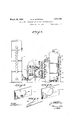
STILL FOR SEPARATING ABSORPTION OIL FROM GASOLINE Filed Nov. 26, 1929 2 Sheets-Sheet 1 Zifiil.
WITNESS Q25 Maig- ATTORNEY STILL FOR SEPARATING ABSORPTION OIL FROM GASOLINE BY (a ATTORNEY Patented Mar. 29, 1932 MEINHARD H. KOTZEIBUE, OF TULSA, OKLAHOMA STILL FOR SEPARATING,ABSORPTI ON OIL FROM GASOLINE Application filed November 26, 1929. SeriaiNo. 409,920.
-This invention relates to a distillation unit associated with an absorber system.
An object of the invention is the provision of a distillation unit connected with I3 an absorber system for removing the light hydrocarbons, suchas gasoline, from a saturated absorption oil which has passed through various steps of treatment before entering the evaporation or distillationunit.
Another object of the invention is the provision of a distillation unit in which thesaturated absorption oil must pass through a tortuous path of an auxiliary heat unit for progressively vaporizinghigh test gasoline from the absorption oil which is collected in a chamber at the bottonrof the still, superheated steam being applied directly to the surface of the collected absorption oil for creating a vapor tension thereon with a consequent evaporation of any high test gasoline in the oil, the superheated steam being conducted through the perforated bubble trays for agitating the absorption oil moving over said trays and in close association with the heating unit.
This invention will be best understood from a consideration of the following detailed description, in view of the accompanying drawings forininga part of the specification; never'theless it is to be understood that the inventionis not confined to the-disclosure, being susceptible er I such changes and ndifia tions whif chgshall define no material departure froin' the? salient features of the invention as o expressed in the appended claims. Inthedrfawings": 5 i i Q Figure 1 is a vle'w in elevat on of; ab-
sorber and distillation unit constructed in :acE j cordance 1 with the principles "my: ,iI, 1 v,e I1 tion, i a F gur 2 is a ver cal se fii oi; h 'd llatiOn 11n 1t, 1 j a;
Figure 3 is a horizontal secltion taken alongg e5 theline i i-30f Figure 2,; ua I. Figure- 1 51S a fragmentary vertical, section;
fie associated with the opposite end of the heating unit, and
Figure 7 is a view in perspective of the base member of the casing associated with the easing shown in Figure 5;
I 'Referrlng more particularly to the draw ings, 1O designates an absorber tower-of well known construction in which the casing head gas is passedthrough a series of baflles or 60 trays where it is absorbed by the usual oil assing by gravity from the top of the tower. 11 and 12 represent storage tanks, respecti'vely, for collecting the lean oil and the saturated oil from the absorber tank 10. Heat exchangers, generally designated by thenumeral 13, are connected between the "tanks 11 and 12 and an evaporator orstill 14.
Referring more particularly to Figures 2 to 4, inclusive, it will be seen that the evaporator still includes a tank 15 located in a vertical position having a bowl-shaped closure 16 in which is incorporated a vapor outlet 17 v A pipe 18 connects the heat exchangers with an inlet 19 of a heating unit 20. This heating unit consists of an outer casing 21 of tubular form having one end 22 connected to the wall of the tank 15 adjacent the opening 19. The other end extends through the tank at a diametrically opposite point and isconnected by means of flanges 23 toa nipple 24. This nipple has an inlet 25"connected= witl1 source of steam and mg unit-20*to'be carried away. The inner I tubular 'i'nember 27=has a rounde'd inner end 28 close tothe casing 21 and spaced from the inner-face of the wall of said casing to provide a hair pin heating --chamber= of restricted areaaround the tubular memberw27 The-chamber 29 is not in 'c'ommunication'with the tubular-member 27 so that the steam front 1 said member does: not; mix with the oil in" the annular chamber 29since'the oil is merely The oil fromthe chamber 29 passes through: an opening 30 in thou-shaped pipe 31 which has two legs extending downwardly=overthe outside-of the exterioriof the casing 21with the lower ends terminatingat 32 in an elon-- 7 means of an opening bubble trays 34 and tray i 34 a purpose which will be gated cup-shaped member 33 mounted on a bubble tray 34 which is located below the heating unit 30.
A second heating unit 35 is located below the heating unit 20 and below the bafile 34 and is of a slightly diiferent construction from the heating unit 20. Thisunit consists of an outer shell 36 having one end'connected to the portion of the wall of the tank while the other end is shown at 37 and passes through the wall at diametrically opposite points. This end is connected with a nipple 38 having a steam inlet 39 and a condenser steam outlet 40. The inner tubular member 41 has its inner end 42 closed and spaced'from the adjacent end of the casing 36 which provides an annular oil passage 43 around the tubular member 41 which is in communication with a restricted space 44 of the tank by or outlet 45 inone. end of the casing 36. The casingdepends from the underface of the bubble tray 34 adjacent the opening 45 and; is spaced from a bafiie 34 A baffle 46 is provided withan opening 50 which receives the casing 36 andalso has a restricted opening 51 adapted to receive a vapor outlet pipe 52 whicheextends upwardly through the bubble tray 34 and thereby prevents any excessive pressure of the hi h test gasoline which has been forced from -t e absorber oil passing" through the annular chamber 43.
One end of the casing 36 is provided with openings 55 located -within a pocket *56 formed by means of an end plate 57 and a bottom plate 58. The end wall 57 of the pocket is provided with an opening 59 through which is inserted the casing 36. The pocket 56 forms a seal to receive the absorber oil flowing over the flange 60 from the end of the bubble tray 34 so that the absorber oil will enter' the openings 55 and pass through the annularchamber43-when said oil is discharged through the-openings-45 onto the next lower bubble tray 34". Itwill be noted that a plurality of these heatin units and bubble trays are arranged in space relation within the tank 15 and are of similar construction to the heating unit 35 and the 34 and these associated elements will therefore not be described in detail.
. Beneath the last heating unit 35- is abubble terminating adjacent the base member :62 and a cup-shaped seal 63. This bubble trayis alsolocated above astoragechamber 64 tor the denuded absorption oil.- All of the bubble'trays are provided with openings 65 :for presently described and angle-irons or'baflies 66: depend from the face of each bubbletrayinspaced relation.
An inlet-67 is connected with a-source of superheated steam under, pressure so that when the steam entersthe chamber 64 above from which depends the baflie 61 toFiO lbs. per square inch is obtained in the vapor chamber 70 at the top of the tank 15.
i drain pipe 71' has a bent end 72 located adjacent the curved bottom 7 3 of the tank and hasan outlet at74. A pipe 7 5 extending inwardly and upwardly within the chamber 34 provides means for the return of oil from the dephlegmator.
A nipple 7 6 is connected with the chamber 64 to provide an oil outlet.
The upper end of the tank is provided with a pair of partitions and 81 spaced from each other. The partition 80 carries short pipes 82 placing the portion of the tank above the heater 20. in communication with a chamber 83tbetw-een the two plates. Short pipes 84 place the chamber 83 in communication with the vaporchamber 70. The elements just described comprise a mist extractor described in Patent No. 1,695,192, dated Deorll, 1928.
. The openings 65 in the various battles pro vide passages for the vapors from the lower most portionsof the absorption tower or tank to the uppermost portion. These perfora tions further providemeans for bringing the absorption 'medium into contact with the gases orv vapors.
I claim:
1. A still for separating gasoline from abend ofeach tray terminating short of an adja- 1 cent wall of the tank and providing a passage for the absorption oil to the pocket to permit oil from a tray to'fiow into the pocket, each unit being in communication with the associated pocketto receive absorption oil, means for supplying the top of the tank with absorptionoil, and means for conducting gasoline vapor from the tank, each unit having an outlet at the opposite end of the unit for discharging absorption oil onto a bubble tray beneath the respective unit.
2. A still for separating gasoline from absorption oil comprising a tank, spaced heating units located transversely in the tank, a bubble tray located beneath each heating imit, a pocket enclosing an end of each unit, one end of each tray terminating short of an adj acent wall of the tank and providing a passage tor the absorption oil to the pocket to permit oil from a tray to flow into the pocket, 1 i
ing units located transversely each unit being in communication with the associated pocket to receive absorption oil, means for supplying the top of the tankwith absorption oil, and means for conducting gasoline vapor from the tank, each unit having an outlet at the opposite end of the unit for discharging absorption oil onto a bubble tray beneath the respective unit, the bottom of the tank having a. chamber for receiving the denuded absorption oil, and means for supplying superheated steam to the surface of the absorption oil in the chamber.
3. A still for separating gasoline from absorption oil comprising a tank, spaced heatof the tank, a bubble tray located beneath each heating unit, a pocket enclosing an end of each unit, one end of each tray terminating short of an adjacent wall of the tank and providing a passage for the absorption oil to the pocket to permit oil from a tray to flow into the pocket, each unit being in communication with the associated pocket to receive absorption oil, means for supplying the top of the tank with absorption oil, and means for conducting gasoline vapor from the tank, each unit having an outlet at the opposite end of the unit for discharging absorption oil onto a bubble tray beneath the respective unit, means for supplying a heating medium to the interior of the heating units, the heating units being provided with passages for conducting the absorption oil through said units in heat interchange relation with the heating me dium.
4. A still for separating gasoline from absorption oil comprising a tank, spaced heating units located transversely in the tank, a bubble tray located beneath each heating unit, a pocket enclosing an end of each unit, one end of each tray terminating short of an adjacent wall of the tank and providing a passage for the absorption oil to the pocket to permit oil from a tray to flow into the pocket, each unit being in communication with the associated pocket to receive absorption oil, means for supplying the top of the tank with absorption oil, means for conducting gasoline vapor from the tank, each unit having an outlet at the opposite end of the unit for discharging absorption oil onto a bubble tray beneath the respective unit, each heating unit having an internal chamber and a chamber externally of the first-mentioned chamber to receive oil from its respective casing, means for supplying the internal chamber with steam.
5. A still for separating gasoline from absorption oil comprising a tank, spaced heating units located transversely in the tank, a hubble tray located beneath each heating unit, a
ocket enclosing an end of each unit, one end of each tray terminating short of an adjacent wall of the tank and providing a passage for the absorption oil to the pocket to permit oil froma tray to flow into the pocket, each unit I being incommunication with the associated pocket to receive absorption oil, means for supplying the top of the tank with absorption oil, means for conducting gasoline vapor from the tank, each unit having an outlet at-the opposite end'of'the unit for discharging absorption oil onto a bubble tray beneath the respective unit, and means adjacent the outlet of each unit for limiting the discharged oil from the unit to the adjacent ends of the bubble trays v I v 6. A still for separa-ting'gasoline from absorption oil comprising a tank. spaced heat ing units located transversely in the tank, a
, bubble tray located beneath each heating unit,
a pocket enclosing an end of each unit, one end of each tray terminating short of an adjacent wall of'the tank and providing a passage for the absorption oil to the pocket to permit oil from a tray to flow into the pocket, each unit beingin communication with the associated pocket to receive absorption oil, means for supplying the top of the tank with absorption oil, and means for conducting gasoline vapor from the tank, each unit having an outlet at the opposite end of the unit for discharging absorption oil onto a bubble tray beneath the respective unit, the bottom of the tank having a chamber for receiving the denuded absorption oil, and means for supplying superheated steam to the surface of the absorption oil in the chamber, the trays being perforated to permit the steam from the storage chamber and vaporized gasoline to circulate around the heating units while causing agitation of the oil on the trays.
7. A still for separating gasoline from absorption oil comprising a tank, spaced heating units located transversely in the tank, a bubble tray located beneath each heating unit, a pocket enclosing an end of each unit, one end of each tray terminating short of an adjacent wall of the tank and providing a passage for the absorption oil to the pocket to permit oil from a tray to flow into the pocket, each unit being in communication with the associated pocket to receive absorption oil, means for supplying the top of the tank with absorption oil, means for conducting gasoline vapor from the tank, each unit having an outlet at the opposite end of the unit for discharging absorption oil onto a bubble tray beneath the respective unit, a battle depending from each bubble tray adjacent the discharge opening and having the lower end terminating short of another bafiie to provide a confined space at the opening for preventing the discharge opening from directly communicating with the space between a pair of baffles.
8. A still for separating gasoline from ab-.
sorption oil comprising a tank, spaced heating units located transversely in the tank, a bubble tray located beneath each heating unit, a pocket enclosing an end of each unit,
' one end ofeachtvay terminating short of an adjacent Wall. of Ethe tank {and v providing. :a passage for th absonpfiw nil tow h packet to permit Qilfnomeat' ay o flew in fihepeck at, each unit being n c mmunic tion with th associat d pocke :to receive absorptio eil, means for supplying the top of the-tank with absorption oil, means for conducting gasoline vap r from the a k, eac unit having; an Oufletat the opposite end of the unit for discharging absorption ,oil onto a buhble tmy beneath the respective unit, a bafile depending from each bubbletrayadj acent the discharge opening and having the lower endteI'm-inat, ingi'short of another bafiie to provide 8:; 30l1' fined space atithe opening ifor preventing the diseha-rge opening from directly-communicatingwi-th thespace between a pair of :baifies, and means providing an escape fol gasoline discharge opening.
MEINHARD H."
yaporsfremthe confinedesp ace adjacent. each KOTZEBUE.
Priority Applications (1)
| Application Number | Priority Date | Filing Date | Title |
|---|---|---|---|
| US409920A US1851849A (en) | 1929-11-26 | 1929-11-26 | Still for separating absorption oil from gasoline |
Applications Claiming Priority (1)
| Application Number | Priority Date | Filing Date | Title |
|---|---|---|---|
| US409920A US1851849A (en) | 1929-11-26 | 1929-11-26 | Still for separating absorption oil from gasoline |
Publications (1)
| Publication Number | Publication Date |
|---|---|
| US1851849A true US1851849A (en) | 1932-03-29 |
Family
ID=23622493
Family Applications (1)
| Application Number | Title | Priority Date | Filing Date |
|---|---|---|---|
| US409920A Expired - Lifetime US1851849A (en) | 1929-11-26 | 1929-11-26 | Still for separating absorption oil from gasoline |
Country Status (1)
| Country | Link |
|---|---|
| US (1) | US1851849A (en) |
-
1929
- 1929-11-26 US US409920A patent/US1851849A/en not_active Expired - Lifetime
Similar Documents
| Publication | Publication Date | Title |
|---|---|---|
| US3326280A (en) | Heat exchanger with baffle structure | |
| US2614816A (en) | Condenser | |
| US1791441A (en) | Refrigerating system | |
| US1516187A (en) | Gas-absorbing apparatus | |
| US1851849A (en) | Still for separating absorption oil from gasoline | |
| US2241621A (en) | Method of and means for separating gases from liquids | |
| US1653387A (en) | Storage tank for volatile liquids | |
| US2952985A (en) | Apparatus for fractionating and refrigerating with or by miscible fluids | |
| US1402340A (en) | Apparatus for extracting vapors from gaseous mixtures | |
| US4469169A (en) | Distribution device for multitubular exchangers | |
| US2048355A (en) | Absorption cold apparatus | |
| US1422008A (en) | Apparatus for purifying coal gas | |
| US1806712A (en) | Cooling system foe | |
| US1738720A (en) | Refrigeration | |
| US2318621A (en) | Refrigeration | |
| US2323186A (en) | Refrigeration | |
| US2164045A (en) | Refrigeration | |
| US415133A (en) | Apparatus for distillation of ammoniacal liquids | |
| DE720112C (en) | Evaporator for absorption refrigerators with auxiliary gas | |
| US1757578A (en) | Refrigeration | |
| US1692053A (en) | Refrigerating machine | |
| US1918608A (en) | Apparatus for condensing hydrocarbons | |
| US1168758A (en) | Vacuum evaporating apparatus. | |
| US1795538A (en) | Refrigerator of the absorption type | |
| US2515081A (en) | Circulating means in absorption refrigeration |