US1851829A - Scythe, straw knife, and the like - Google Patents
Scythe, straw knife, and the like Download PDFInfo
- Publication number
- US1851829A US1851829A US322991A US32299128A US1851829A US 1851829 A US1851829 A US 1851829A US 322991 A US322991 A US 322991A US 32299128 A US32299128 A US 32299128A US 1851829 A US1851829 A US 1851829A
- Authority
- US
- United States
- Prior art keywords
- scythe
- bridges
- rail
- blade
- fastening
- Prior art date
- Legal status (The legal status is an assumption and is not a legal conclusion. Google has not performed a legal analysis and makes no representation as to the accuracy of the status listed.)
- Expired - Lifetime
Links
- 239000010902 straw Substances 0.000 title description 4
- 210000002105 tongue Anatomy 0.000 description 9
- 238000012986 modification Methods 0.000 description 7
- 230000004048 modification Effects 0.000 description 7
- 229910000831 Steel Inorganic materials 0.000 description 4
- 239000010959 steel Substances 0.000 description 4
- 235000013311 vegetables Nutrition 0.000 description 2
- 238000005452 bending Methods 0.000 description 1
- 238000003780 insertion Methods 0.000 description 1
- 230000037431 insertion Effects 0.000 description 1
- 239000000463 material Substances 0.000 description 1
Images

Classifications
-
- A—HUMAN NECESSITIES
- A01—AGRICULTURE; FORESTRY; ANIMAL HUSBANDRY; HUNTING; TRAPPING; FISHING
- A01D—HARVESTING; MOWING
- A01D1/00—Hand-cutting implements for harvesting
- A01D1/02—Scythes
Definitions
- the invention relates to scythes, straw knives and the like and more specially to Scythes of the kind described in Patent N 0. 1,628,589, in which an interchangeable steel cutting blade or strip is arranged on a blunt main scythe blade by means of a special fastening rail, said rail being rigidly connected with said steel blade, whereby it is possible to utilize relatively thin strips by pressing i together the scythe blade with the interchangeable blade and the rail.
- the latter has to be very thin and should offer sufficient resistance against bending.
- the rail also has to be made of thin material in order to avoid excessive weight. These parts should offer a certain degree of stiffness and this is effected I by tightly fastening them on the main blade,
- the object of the invention is a further development of a scythe of the kind described and an improved connection of its parts, fulfilling the aforesaid requirement, and in which the fastening of the three parts of the scythe, i. e. the main blade, the cutting strip and the fastening rail, is effected by wedging them together without any remarkable increase of weight.
- Fig. 8 is a section on line CD of Fig. 7;
- Fig. 11 shows this fastening rail assembled H vided in which bridges 2 enter, so that the steel cutting strip lies flat on the surface of the main blade.
- the fastening rail 5 is provided with apertures 6 of larger size in the longitudinal direction than the U-shaped bridges 2' projecting from the plain blade. 1
- the fastening. rail 5 is laid flat upon the blade 3.
- the apertures 6 of the rail '5 are provided with tongues 7 which, by shifting the rail 5 towards the end of the blade 1, enter below the U-shaped bridges.
- These tongues 7 are tapered, whereby the blade 3 may be pressed against the main blade 1, the
- the longitudinal tongues 7 are tapered towards the outer end of the scythe and the bridges 2 are correspondingly tapered in the same direction.
- the rail By shifting the rail towards the outer end of the scythe the three parts of the scythe 1, 3, 5 are pressed tightly together.
- the. fastening rail i'sprovided at. the larger scythe end with main blade 1 .(Fig. 6), the other featuresof the three parts of the scythe being the same as in the modification shown in Figs. 1 to 5.
- the fastening rail 5 is provided, above the apertures 6 and corresponding longitudinal tongues 7, with a pocket 11 open only at one side opposite to the tongues and serving as a guide along the bridges 2 or along the guides 10 respectively, in inserting the rail 5 and at the same time preventing vegetable matte from intruding into the apertures.
- a pocket 12 open at the top is provided which permits insertion of rail 5 from below transversely over said bri ges.
- a device of the character described including a main blade, a series of U-shaped bridges carried thereby, a cutting blade engageable with the bridges, a fastening strip having apertures to receive the bridges, and
- a lateral tongue in each aperture adapted to 7 enter between the bridges and surface of the cutting blade to lock the parts together.
- a device of the character described including a main blade, a series of U-shaped bridges carried thereby having beveled bearing surfaces, a cutting blade engageable with the bridges, a fastening strip having apertures to receive the bridges and a tapered tongue in each aperture adapted to engage the beveled surfaces of the bridge and thereby exert a wedging action on the cutting blade.
- a device of the character described including a main blade, a series of U-shaped bridges carried thereby, a cutting blade engageable with the bridges, a fastening strip having apertures to receive the bridges, and a lateral tongue in each aperture adapted to enter between the bridges and surface of the cutting blade to lock the parts together, and pockets on the fastening strip to partly cover said apertures and forming guides for said bridges.
- a device of the character described including a main blade, a series of U-shaped bridges carried thereby, a cutting blade engageable with the bridges, a fastening strip having apertures to receive the bridges, and a lateral tongue in each aperture adapted to enter between the bridges and surface of the cutting blade to lock the parts together, and pockets on the fastening strips adapted to partly cover the apertures and open on one I have signed my name.
Landscapes
- Life Sciences & Earth Sciences (AREA)
- Environmental Sciences (AREA)
- Shearing Machines (AREA)
Description
March 29, 1932. GQNYK 1,851,829
SCYTHE, STR'AW KNIFE, AND THE LIKE Filed Dec. 1, 1928 2 Sheets-Sheet 1 Fig.1
March 29, 1932. GONYK 1,851,829
SCYTHE, STRAW KNIFE, AND THE LIKE Filed Dec. 1, 1928 g Sheets-Sheet 2 Fig.6
40 N I W a a 1 Patented Mar. 29,1932
IGNATZ GON'YK, F
PATENT VIENNA, aus'rnra OFFICE,
SCYTHE, STRAW KNIF AND E LIKE Application filed December 1, 1928, Serial No.
The invention relates to scythes, straw knives and the like and more specially to Scythes of the kind described in Patent N 0. 1,628,589, in which an interchangeable steel cutting blade or strip is arranged on a blunt main scythe blade by means of a special fastening rail, said rail being rigidly connected with said steel blade, whereby it is possible to utilize relatively thin strips by pressing i together the scythe blade with the interchangeable blade and the rail.
To avoid a weight exceeding that of an ordinary scythe without impairing the required rigidity of the strip, the latter has to be very thin and should offer sufficient resistance against bending. The rail also has to be made of thin material in order to avoid excessive weight. These parts should offer a certain degree of stiffness and this is effected I by tightly fastening them on the main blade,
the increase of Weight due to the fastening means thus being only very small.
The object of the invention is a further development of a scythe of the kind described and an improved connection of its parts, fulfilling the aforesaid requirement, and in which the fastening of the three parts of the scythe, i. e. the main blade, the cutting strip and the fastening rail, is effected by wedging them together without any remarkable increase of weight.
Several modifications of thescythe forming the object of the present invention are illustrated in the accompanying drawings wherein,
Figure 1 is the main blade of the scythe; Fig. 2 the fastening rail; Fig. 3 the steel cutting blade; Fig. 4c the assembled scythe; Fig. 5 is a section along line AB of Fig. on an enlarged scale; Fig. 6 is the same section of a modification; Fig. 7 is a view of a further modification of the fastening rail;
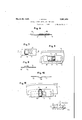
Fig. 8 is a section on line CD of Fig. 7; Fig. 9 is an assembled view of the structures shown in Figs. 6 and 7 Fig. 10 is a modification of the fastening rail seen from above in the position shown in Fig. 11; and
322,991, and in Germany December 2, 1927;
Fig. 11 shows this fastening rail assembled H vided in which bridges 2 enter, so that the steel cutting strip lies flat on the surface of the main blade. The fastening rail 5 is provided with apertures 6 of larger size in the longitudinal direction than the U-shaped bridges 2' projecting from the plain blade. 1 The fastening. rail 5 is laid flat upon the blade 3. In order to fasten the blades 1 and 3 together the apertures 6 of the rail '5 are provided with tongues 7 which, by shifting the rail 5 towards the end of the blade 1, enter below the U-shaped bridges. These tongues 7 are tapered, whereby the blade 3 may be pressed against the main blade 1, the
assembled parts fastening rail, main blade and cutting blade) then forming a unit.
In order to obtain a tight connection of these parts the longitudinal tongues 7 are tapered towards the outer end of the scythe and the bridges 2 are correspondingly tapered in the same direction. By shifting the rail towards the outer end of the scythe the three parts of the scythe 1, 3, 5 are pressed tightly together. In order to facilitate shifting by hand and to prevent parts of vegetable matter or the-like being caught, the. fastening rail i'sprovided at. the larger scythe end with main blade 1 .(Fig. 6), the other featuresof the three parts of the scythe being the same as in the modification shown in Figs. 1 to 5.
In the modification according to Figs. 7 to 9 the fastening rail 5 is provided, above the apertures 6 and corresponding longitudinal tongues 7, with a pocket 11 open only at one side opposite to the tongues and serving as a guide along the bridges 2 or along the guides 10 respectively, in inserting the rail 5 and at the same time preventing vegetable matte from intruding into the apertures.
As in certain scythes when interchanging the blades it is inconvenient to put the fastening rail on in its correct position so that the pockets will overlap the U-shaped bridges. In the modification according to Figs. 10 and 11 a pocket 12 open at the top is provided which permits insertion of rail 5 from below transversely over said bri ges.
In testimony that I claim the foregoing as my invention,
by a transverse and a subsequent longitudiv nal shifting movement. The upper opening of this pocket passes over the U-shaped bridges 2 or the guides 10 (Fig. 6) respectively until correct position for engagement of the parts is obtained by longitudinal shifting of the rail.
I claim- 1. A device of the character described including a main blade, a series of U-shaped bridges carried thereby, a cutting blade engageable with the bridges, a fastening strip having apertures to receive the bridges, and
a lateral tongue in each aperture adapted to 7 enter between the bridges and surface of the cutting blade to lock the parts together.
2. A device of the character described, including a main blade, a series of U-shaped bridges carried thereby having beveled bearing surfaces, a cutting blade engageable with the bridges, a fastening strip having apertures to receive the bridges and a tapered tongue in each aperture adapted to engage the beveled surfaces of the bridge and thereby exert a wedging action on the cutting blade.
3'. A device of the character described including a main blade, a series of U-shaped bridges carried thereby, a cutting blade engageable with the bridges, a fastening strip having apertures to receive the bridges, and a lateral tongue in each aperture adapted to enter between the bridges and surface of the cutting blade to lock the parts together, and pockets on the fastening strip to partly cover said apertures and forming guides for said bridges. l r
4. A device of the character described including a main blade, a series of U-shaped bridges carried thereby, a cutting blade engageable with the bridges, a fastening strip having apertures to receive the bridges, and a lateral tongue in each aperture adapted to enter between the bridges and surface of the cutting blade to lock the parts together, and pockets on the fastening strips adapted to partly cover the apertures and open on one I have signed my name.
IGNATZ GONYK.
Applications Claiming Priority (1)
| Application Number | Priority Date | Filing Date | Title |
|---|---|---|---|
| DE1851829X | 1927-12-02 |
Publications (1)
| Publication Number | Publication Date |
|---|---|
| US1851829A true US1851829A (en) | 1932-03-29 |
Family
ID=7746047
Family Applications (1)
| Application Number | Title | Priority Date | Filing Date |
|---|---|---|---|
| US322991A Expired - Lifetime US1851829A (en) | 1927-12-02 | 1928-12-01 | Scythe, straw knife, and the like |
Country Status (1)
| Country | Link |
|---|---|
| US (1) | US1851829A (en) |
Cited By (4)
| Publication number | Priority date | Publication date | Assignee | Title |
|---|---|---|---|---|
| JPS48114184U (en) * | 1972-03-31 | 1973-12-27 | ||
| US5689889A (en) * | 1996-08-28 | 1997-11-25 | Overholt; Steven D. | Knife with replaceable cutting element |
| US6574868B1 (en) | 2000-03-01 | 2003-06-10 | Steven D Overholt | Knife with replaceable cutting element |
| USD702583S1 (en) * | 2012-02-14 | 2014-04-15 | Entreprise T.R.A. (2011) Inc. | Member for translocating roadway markers |
-
1928
- 1928-12-01 US US322991A patent/US1851829A/en not_active Expired - Lifetime
Cited By (4)
| Publication number | Priority date | Publication date | Assignee | Title |
|---|---|---|---|---|
| JPS48114184U (en) * | 1972-03-31 | 1973-12-27 | ||
| US5689889A (en) * | 1996-08-28 | 1997-11-25 | Overholt; Steven D. | Knife with replaceable cutting element |
| US6574868B1 (en) | 2000-03-01 | 2003-06-10 | Steven D Overholt | Knife with replaceable cutting element |
| USD702583S1 (en) * | 2012-02-14 | 2014-04-15 | Entreprise T.R.A. (2011) Inc. | Member for translocating roadway markers |
Similar Documents
| Publication | Publication Date | Title |
|---|---|---|
| US2718695A (en) | Pocket knife | |
| US1851829A (en) | Scythe, straw knife, and the like | |
| DE2705886A1 (en) | FOLDER | |
| KR850000218A (en) | Space composition of unit components in the slide fastener chain | |
| GB318893A (en) | Improvements relating to sheet piling | |
| US2112790A (en) | Claw clipper for birds and dogs | |
| DE3420095C2 (en) | Gripping device, in particular for picking up animal droppings from the floor | |
| US864105A (en) | Cigar-wrapper cutter. | |
| US1523318A (en) | Beehive cover | |
| DE575890C (en) | Safety razor blade with a cutting edge | |
| US794234A (en) | Nail-trimmer. | |
| US1950255A (en) | Box fastener | |
| US1357137A (en) | Combination cane stripper and knife | |
| US1529237A (en) | Shears | |
| US1059894A (en) | Knife-gage. | |
| DE202008016272U1 (en) | Measuring element for chainsaw | |
| US1616424A (en) | Line cutter | |
| US9732A (en) | Pocket-comb | |
| US1407735A (en) | Bale marker | |
| US1991318A (en) | Paper fastener | |
| US1840912A (en) | Combined rip and crosscut saw | |
| DE383723C (en) | Tobacco humidifiers | |
| US1005193A (en) | Safety-razor. | |
| US1228019A (en) | Type-binder. | |
| US819455A (en) | Can-opener. |