US1851791A - Electric windshield cleaner - Google Patents
Electric windshield cleaner Download PDFInfo
- Publication number
- US1851791A US1851791A US411147A US41114729A US1851791A US 1851791 A US1851791 A US 1851791A US 411147 A US411147 A US 411147A US 41114729 A US41114729 A US 41114729A US 1851791 A US1851791 A US 1851791A
- Authority
- US
- United States
- Prior art keywords
- carriage
- casing
- belt
- windshield
- wiper
- Prior art date
- Legal status (The legal status is an assumption and is not a legal conclusion. Google has not performed a legal analysis and makes no representation as to the accuracy of the status listed.)
- Expired - Lifetime
Links
- 230000033001 locomotion Effects 0.000 description 38
- 238000010276 construction Methods 0.000 description 20
- 238000005461 lubrication Methods 0.000 description 10
- 230000007246 mechanism Effects 0.000 description 10
- 210000005069 ears Anatomy 0.000 description 7
- 239000003643 water by type Substances 0.000 description 6
- 239000000463 material Substances 0.000 description 5
- 229910000906 Bronze Inorganic materials 0.000 description 4
- 229910000760 Hardened steel Inorganic materials 0.000 description 4
- 239000010974 bronze Substances 0.000 description 4
- 238000004140 cleaning Methods 0.000 description 4
- KUNSUQLRTQLHQQ-UHFFFAOYSA-N copper tin Chemical compound [Cu].[Sn] KUNSUQLRTQLHQQ-UHFFFAOYSA-N 0.000 description 4
- 229910001369 Brass Inorganic materials 0.000 description 2
- OKTJSMMVPCPJKN-UHFFFAOYSA-N Carbon Chemical compound [C] OKTJSMMVPCPJKN-UHFFFAOYSA-N 0.000 description 2
- 230000015572 biosynthetic process Effects 0.000 description 2
- 239000010951 brass Substances 0.000 description 2
- 229910002804 graphite Inorganic materials 0.000 description 2
- 239000010439 graphite Substances 0.000 description 2
- 238000004519 manufacturing process Methods 0.000 description 2
- 239000002184 metal Substances 0.000 description 2
- 230000004048 modification Effects 0.000 description 2
- 238000012986 modification Methods 0.000 description 2
- 238000003825 pressing Methods 0.000 description 2
- 230000035939 shock Effects 0.000 description 2
- 241000582342 Carria Species 0.000 description 1
- 206010010071 Coma Diseases 0.000 description 1
- 229920000742 Cotton Polymers 0.000 description 1
- LFVLUOAHQIVABZ-UHFFFAOYSA-N Iodofenphos Chemical compound COP(=S)(OC)OC1=CC(Cl)=C(I)C=C1Cl LFVLUOAHQIVABZ-UHFFFAOYSA-N 0.000 description 1
- 206010043268 Tension Diseases 0.000 description 1
- 239000006096 absorbing agent Substances 0.000 description 1
- 239000011324 bead Substances 0.000 description 1
- 238000005452 bending Methods 0.000 description 1
- 230000000694 effects Effects 0.000 description 1
- 238000002474 experimental method Methods 0.000 description 1
- 239000002783 friction material Substances 0.000 description 1
- 238000007689 inspection Methods 0.000 description 1
- 230000003137 locomotive effect Effects 0.000 description 1
- 230000001050 lubricating effect Effects 0.000 description 1
- 239000000203 mixture Substances 0.000 description 1
- 238000000465 moulding Methods 0.000 description 1
- 229920000136 polysorbate Polymers 0.000 description 1
- 239000004576 sand Substances 0.000 description 1
- XLYOFNOQVPJJNP-UHFFFAOYSA-N water Substances O XLYOFNOQVPJJNP-UHFFFAOYSA-N 0.000 description 1
Images

Classifications
-
- B—PERFORMING OPERATIONS; TRANSPORTING
- B60—VEHICLES IN GENERAL
- B60S—SERVICING, CLEANING, REPAIRING, SUPPORTING, LIFTING, OR MANOEUVRING OF VEHICLES, NOT OTHERWISE PROVIDED FOR
- B60S1/00—Cleaning of vehicles
- B60S1/02—Cleaning windscreens, windows or optical devices
- B60S1/04—Wipers or the like, e.g. scrapers
- B60S1/06—Wipers or the like, e.g. scrapers characterised by the drive
- B60S1/16—Means for transmitting drive
- B60S1/18—Means for transmitting drive mechanically
- B60S1/20—Means for transmitting drive mechanically by cable drives; by flexible shafts
-
- B—PERFORMING OPERATIONS; TRANSPORTING
- B60—VEHICLES IN GENERAL
- B60S—SERVICING, CLEANING, REPAIRING, SUPPORTING, LIFTING, OR MANOEUVRING OF VEHICLES, NOT OTHERWISE PROVIDED FOR
- B60S1/00—Cleaning of vehicles
- B60S1/02—Cleaning windscreens, windows or optical devices
- B60S1/04—Wipers or the like, e.g. scrapers
- B60S1/32—Wipers or the like, e.g. scrapers characterised by constructional features of wiper blade arms or blades
- B60S1/34—Wiper arms; Mountings therefor
- B60S1/3402—Wiper arms; Mountings therefor with means for obtaining particular wiping patterns
- B60S1/3404—Wiper arms; Mountings therefor with means for obtaining particular wiping patterns the wiper blades being moved substantially parallel with themselves
Definitions
- CHAR-LES B WATERS, OF MONTCLAIR, NEW JERSEY: JULIA K. WATERS ADMINISTRAF TRIX OF SAID CHARLES B. WATERS, DECEASED ELECTRIC WINDSHIELD CLEANER Application filed December 2, 1929. Serial No. 411,147.
- the present invention relates to cleaners suitable for use as windshield cleaners of automobiles, locomotives, aeroplanes, windows of sky scrapers, and the like,and coma prises improvements in the mechanism disclosed in my patent numbered 1,555,341 issued September 29, 1925.
- a primary object of the present invention is to provide a window or windshield cleaner of light weight durable construction, in which the necessity of lubrication is eliminated, and in which frictional resistance to motion and noise of operation is minimized, and a minimum driving power is required.
- Another ob]ect o my invention is to provide a cleaner of the character mentioned, embodying a novel electric motor drive in which gearing between the motor and the wiper elements is entirely eliminated and the motor is operable at constant speed independ ently of voltage supply variations, and with an expenditure of electrical energy substan-. tially less than that generated at normal speed m built up in standard sections, each section provided with a wiper element whereby standard motor mechanisms and parts may be utilized for building up cleaners of variable lengths.
- Still another object of my invention is to provide an improved, efficient and durable cleaner of comparatively simple construction adapted to be manufactured by quantity production methods at low cost.
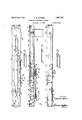
- Figure 1 is a broken elevational View of a cleaner constructed in accordance with one embodiment of my invention, the view being observed from within a windshield with which the cleaner is associated.
- Figure 2 is a vertical sectional View on a plane represented by line 22 in Figure 1, a portion of a windshield being indicated in section showing the operative association therewith of the cleaner.
- Figure 3 is a broken top plan View of the construction illustrated in Figures 1 and 2.
- Figure 4 is an elevational view of a belt pulley and adjustable bracket therefor constituting one of the important features of the present invention.
- Figure 5 is a view partly in elevation and partly in vertical section of the bracket illustrated in Figure 4c, the View being observed at right angles to Figure 4 and from the left side thereof.
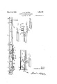
- Figure 6 is a transverse cross sectional view of a modified form of tube or casing for use with my invention.
- Figure 7 is a view similar to Figure 6 disclosing a still further modified form of casing for use with my invention.
- Figure 8 is a view similar to Figure 1 disclosing a modified embodiment of the invention.
- Figure 9 is a top plan view of the construction illustrated in Figure 8.
- Figure 10 is a view similar to Figure 1 disclosing a still further embodiment of the invention.
- Figure 11 shows a modified arrangement ill I on
- Casing 11 may be secured in any desired manner, but as indicated it is preferably secured to the upper horizontal reach w of the frame of the windshield by means of brackets 13 any desired number of which may be employed and which are removably secured to frame by screws 14, the brackets 18 engaging outer wall 11 of casing 11 and being secured thereto in any desired manner.
- Casing 11 provides a housing for the wiper moving mechanism and is provided with beads 15 at the inner edges of walls 11 forming guide rails for grooved Wheels 16 of a carriage 17.
- Carriage 17 is of relatively light construction comprising a horizontal plate member 18 from one ed e of which depends a plurality of ears 19 to which wheels 16 are rotatably secured by means of spindles 21. .lVheels 16 are j ournaled on spindles or pins 21, have long bearing surfaces and are large in diameter compared to the diameter of spindles 21. This provides a minimum frictional resistance against rotation of the wheels and a good bearing surface.
- the wheels being relatively large in diameter their speed of rotation is slow so that wear is minimized and anti-friction supports are provided for the wheels which eliminate the necessity for lubrication in operation.
- rubber tires or rims may be provided therefor if desired and the hubs or centers may be of metal such as brass, bronze, graphite bronze or the like, while pins 21 should be of hardened steel.
- the wheels 19 are preferably of such large diameter that at a speed of sixty strokes per minute, the wheels revolve at less than 1000 revolutions per minute.
- Carriage 17 further is provided with arms 22 depending from plate member 18, each provided with actuating projections 23 for a purpose later referred to, the arms 22 as well as projections 23 being arranged at opposite ends and on opposite sides of plate member 18 as is more clearly indicated in Figure 3.
- Carriage 17 further comprises an arm 24 which as more clearly indicated in Figure 2 is so disposed relative to member 18 that in the assembled position of carriage 17, arm 24 projects through opening 12 in casing 11 and terminates substantially below casing 11 in longitudinally spaced apertured ears 25 through which ears extend a pintle 26 on which and between ears 25 is rotatably mounted a hub 27 of wiper supporting arms 28, which at the free ends thereof are pivotally secured as by a cotter 29 or otherwise to a wiper element 31.
- Surrounding hub 27 and suitably secured to arm 2 1 is a helical spring 32 under sufficient tension to yieldably urge wiper 31 into wiping contact with windshield W as indicated in Figure 2, with a pressure of from two to twelve ounces.
- Carriage body 17 is adapted to be constructed from sheet metal by stamping operations, thus considerably ducing theexpense of manufacture in quantities thereof. It will be noted upon inspection of Figure 1 that three ears 19 are provided, the central one of which is shorter than the others so that wheels 16 are rotatably supported on ears 19 in such manner that the center wheel 16 engages upper track 15 while the other two wheels 16 engage the lower track 15.
- the carriage 17 is securely supported by a three point support against tilting and for reciprocating motion longitudinally of casing 11.
- friction is reduced to a minimum and by the disposition of the wheels as disclosed, twisting strains induced by the yieldable reaction of wiper 01 are avoided.
- My improved carriage is accordingly, of such construction and cooperates with casing 11 in such a manner that a minimum of power is required for moving same longitudinally of casing 11 to impart reciprocating movement to wiper 31 lengthwise of windshield W, while at the same time a rigid and durable construction is provided.
- Carriage 17 comprising the wheels 10, is positioned within casing 11 from either end thereof during assembly of the cleaner and the ends of casing 11 are closed by plates 31 provided with flanges 35 removably secured to casing 11 by screws 36.
- the can riage is preferably disengaged from its driving means somewhat before it reaches the ends of its movement, the inertia of the carriage being relied upon to complete the move ment of the ends of the wiper stroke, thereby reducing the stopping impact of the carriage.
- My invention comprises novel means for imparting reciprocating motion to carriage 17, which in a preferred embodiment thereof comprises an endless belt 39 operatively engaged with pulleys 41 and 42, disposed adjacent the opposite ends of casing 11.
- Pulley 41 is preferably provided with a friction surface for example, by molding rubher or similar compositions over a metallic sleeve or core, and is secured to the vertically arranged armature shaft 43 of a motor 44 suitably secured to casing 11 and which will be described lllOTu in detail hereinafter.
- Pulley 42 is mounted on vertically disposed shaft 45 the opposite ends of which are support ed in base 46 and vertically spaced horizontal arm 47 of a bracket 48.
- Bracket 48 is provided with legs 49 at the corners of the rectangular base 46 which coact with the cas- 'ing walls and serve to hold the bracket 49 in casing 11 between wall 11 and lower track 15 in proper position while permitting ready longitudinal adjustment of the bracket without disturbing the proper alignment of the carrier.
- the bracket 48 is adjustable longitudinally of casing 11 to permit convenient adjusting of the tension in belt 39, the adjustment being provided for by the provision of an elongated slot 51 in bottom wall 11 of casing 11 through which slot projecis a screw 52 threadedly engaged in a tapped hole 53 in base 46 of bracket 48. It will accordingly be seen that by loosening screw 52, bracket 48 may be moved longitudinally of casing 11 with screw 52 riding in slot 51 to the desired position, after which screw 52 may be tightened to securely hold bracket 48 in the adjusted position.
- the device should be constructed to require no lubrication; and, second, it is highly importantv that tile cleaner be capable of operation at relatively low amperage.
- wheels 16 roll on tracks 15 under minimum friction whereby carriage 17 is adapted for reciprocation with little power and lubrication of the tracks and rollers is not required.
- the pulley 41 which is carried on the motor shaft 43, no outboard bearing for the motor shaft being utilized, there- 'by eliminates the necessity for lubrication since shaft 43 as in common practice, does not require lubrication. In this way, it will be seen that the number of bearings is reduced to a minimum, thereby minimizing friction and costs.
- this pulley is preferably constructed of a low friction coefiicient material in contact with hardened steel, such for example as brass, bronze, or
- pulley 42 should be at least three times the diameter of shaft 45 for a suitable antifriction support requiring no lubrication.
- washers 55 Surrounding shaft 45 and disposed between the opposite ends of pulley 42 and base 46 and arm 47 are washers 55 which are rela tively smallin diameter and which if desired may be replaced by integral extensions of pulley 42 or bracket 48.
- the shaft 45 being of case hardened steel may be of the very small diameter mentioned and still strong enough to withstand the operating stresses, and at the same time offers such a small moment of frictional resistance to rotation of the pulley 42 that lubrication is not required, and very little resistance to motion is'offered by pulley 42.
- This arrangement therefor provides alow cost anti-friction construction completely eliminating the necessity for lubrication.
- Belt 39 extends through carriage 17 be tween the opposite arms 22 as is clearly indicated in Figure 3, and as the belt cooperates with substantially small pulleys it is highly important that the belt, in order to go around the pulleys without appreciable effort 1 or resistance, be thin, flexible, strong, and yet must not permanently stretch appreciably but should be somewhat resilient.
- the belt used should follow the contour of a pulley not over inch in diameter with a pull applied thereto of not over five pounds.
- Belt 39 is accordingly preferably a closely woven cotton product approximately of an inch thick and of an'inch wide which I have discovered by extensive experiment provides a very satisfactory, suitable, and durable Becausesmall pulleys are used, the pulley 41 or belt 39,0r both, are preferably faced with suitable friction materials, or provided with surface having relatively high coeflicients of friction so that a friction surface is interposed between the belt and pulley and the driving pulley maintains a good grip on the belt in operation.
- Belt 39 has suitably secured thereto as by stitching or riveting in a single line, a clip 57 which as indicated in Figure 3 is of angular formation and is adapted for successive driving engagement with projections 23 which are like wise of angular formation ina manner hereinafter referred to. Stitching or riveting clip 57 to the belt in a single line avoids interference with the flexibility of the belt.
- the belt 39 may be continuous, it is preferable to provide a connection whereby the belt may be adjusted as to length as when applying the cleaner to Windshields of different lengths.
- the belt39 is preferably connected by a wire clip 58 which as indicated in Figures 1 and. 3, is engaged in adjacent looped portions 59 formed by bending back opposite ends of a belt strip and stitching same as indicated at 61, with a single line of stitching. A double line of stitching tends to make the belt too stiff at the joints to pass over the pulley.
- the distance between the ends of the belts after the joint is completed must notrbe too small or the joint will not ride over the pulley properly. In practice this distance should not be less than one-third of the pulley diameter, or not less than of an inch with inch pulleys.
- the belt 39 is continuously driven through frictional contact with pulley 41 fixed to the motor armature shaft 43.
- the clip 57 carried thereby will alternately engage the projections 23 on the opposite sides of carriage 17, moving and imparting reciprocating motion lengthwise of casing 11 to the carriage.
- clip 57 moves to the right as is more clearly indicated in Figure 3, it will engage the front projection 23 and impart movement of carriage 17 commensurate with the movement of belt 39 and clip 57 will remain in driving engagement with projection 23 until the clip 57 begins its arcuate movement around pulley 41 at which instant clip 57 will slide on projection 23 until upon further movement of clip 57 around pulley 41, the projection 23 will be entirely disengaged thereby.
- projections 23 are widely spaced and are angular, while clip 57 is arranged on belt 39 at a similar angle inclined in the direction of travel of the belt.
- the angular clip and projection arrangement provides a firm engagement of the clip with the projections during carriage driving movements
- the spacing of projections 23 is important as it permits clip 57 to pass around pulley 42 to position for engagement with the other clip 23 before the center of the carriage is past the pulley.
- Motor 44 is therefore capable of imparting reciprocating movement to carriage 17 for a windshield wiper of an ordinary automobile, wiping entirely across the windshield with an expenditure of electrical energy not exceeding six amperes.
- the con struction is thoroughly practicable with motor vehicles which during the day at normal speed generate approximately ten amperes and accordingly, the cleaner can be operated continuously without drain on the battery.
- FIGS 6 and 7 are illustrated modified forms of casing 11.
- the casing 11 is provided with vertically alined tracks 15 which are preferably formed by pressing the material of casing 11 inwardly.
- casing 11" is provided with vertically disposed tracks 15 preferably formed by pressing the material of easing 11 outwardly.
- the tracks are disposed closely adjacent the back walls of the casing so that less tendency is present to deform the tracks than in the first form of the invention where the tracks 15 are arranged at the free edges of the horizontal walls of casing 11.
- wheels of carriage 17 will be disposed on the opposite side from that indicated in the first form of the invention and while tracks 15 are adapted for coperation with grooved 5 wheels such as the wheels 16', wheels having rounded or beaded peripheries willbe utilized for engagement in the channel tracks 15 disclosed in Figure 7.
- FIGS 8 and 9 is disclosed a modification of the invention whereby two wipers are utilized instead of a single wiper as disclosed in the first form of the invention.
- two carriages 17 are provided which are preferably of the same construction as carriage 17 in the first form of the invention. In this form of the invention, however, only one of the carriages 17 is reciprocated by the belt 39 in the same manner as disclosed in the first form of the invention.
- Each of'the carriages 17 is provided with an arm 24 for supporting wiper supporting arms 28.
- the idling pulley 42 is disposed substantially centrally of the width of the windshield and the two carriages 17 disposed in such spaced relation that a wiper carried by each of the arms 28 will wipe approximately one half of the width of the windshield.
- the right hand carriage 17 is reciprocated by belt 39 in the same manner as carriage 17 in the first form of the invention and the left hand carriage 17 is connected with the right hand carriage by a rod 75, which as indicated in Figure 8, extends through the ears 29 of both of the arms 24 thus providing pintles for the connection of arms 28 with arms 24, helical springs 76 being disposed about the pintle portions of rods 7 5 and suitably connected with arms 24 and 28 for yieldably urging the wipers into wiping engagement with the windshield.
- the rod 75 embodies a turn buckle connection 77 so that the length thereof may be varied for varying the distance between carriages 17 for different width windshields so the wipers carried by arms 28' will move to the extreme ends of the windshield.
- yieldable means are provided whereby carriage 17 driven by belt 39 is set into movement by motor 44 prior to the other carriage 17 and the latter carriage is gradually set into movement so that the starting efiort is substantially less than would be necessary if motor 44 were required to impart movement to both carriages 17 simultaneously.
- This is accomplished by providing a helical spring ,7 8 surrounding rod 75 on each side of arm 24' of the belt propelled carriage 17, sprin '78 being maintained in contact with cars 25 of arm 24 by cotters or like devices 7 9 extending through rod 7 5.
- the springs 78 provide shock absorbers and further provide a yieldable connection between the two carriages 17 whereby the left carriage 17 will be gradually set into movement by the belt driven carria e 17 in either direction thereof, thus apprecia ly reducing the starting ,eflort on motor 44.
- motor 44 may be operated at one half the speed as in the first form of the invention if applied to a windshield of the same width and still secure the same. wiping effect, or if the motor be oper ated at the same speed, twice the area will be cleaned.
- the casing 11 of the form disclosed in Figures 8 and 9 may be substantially twice the length of casing 11 in the first form of the invention and by the provision of two wipers 31, the same wiping action. on the longer windshield will be secured for the same speed of motor 44.
- casing 11 in the construction disclosed in Figures 8 and 9 may be a one piece casing equal in length to that disclosed in the first form of V the invention for effecting a double wiping action at the same motor speed or the same wiping action at one half the motor speed
- the. casing 11 may be substantially double the length of that disclosed in the first form of the invention whereby each wiper 31 will clean one half of the windshield.
- the casing 11 however may be of any desired length such that the two wipers 31 will travel substantially to the opposite sides of the windshield even though an overlap of wiping action results adjacent the center of the windshield.
- the casing 11 may be of sectional formaditional section may be suitably secured in abutting relation'to the main casing section, as indicated by dot and dash line 81 for providing a casing of suitable length.
- the added casing section need not be provided with a bumper 38 since the springs 7 8 on rod 75 will provide a cushioned stop for the left hand carriage 17.
- windshield cleaners maybe readily provided for windshields of any width by the provision of a standard length casing 11 provided with the reclproeating wiper mechanism in the manner above disclosed and by providing casing sections of varying lengths whereby a cleaner can readily be provided for a windshield of greater width than the standard casing 11 by the addition'thereto of a casing section of the required length and providing a second carriage17 equipped with a wiper 31 and interconnecting the two carriages 17 in the manner above dlsclosed.
- the arm 24 of the left hand carriage 17 is provided with cars 84; for receiving a pintle 85 on which is rotatably journaled a hub 86 of a third wiper supporting arm 87.
- This construction provides a cleaner embodying three reciprocating wipers, one of which wipes substantially the right hand half of the windshield while a double wiping action is secured on the left hand half of the windshield which is the portion affording vision to the operator and accordingly requires more thorough cleaning.
- the casing 11 in the construction disclosed in Figure 10 may be of any desired length or a standard length section may be provided as in Figures Sand 9 adapted for detachable connection therewith of another casing section in which the left hand carriage is supported to provide cleaners of various lengths.
- a plurality of drain holes may be provided in the bottom wall of the casing.
- FIG. 11 a modification of the invention is shown in which an automatic adjusting arrangement for the bracket supporting pulley 42 is provided by means of which a predetermined tension is maintained on the belt regardless of stretching or shrinkage that may occur in operation of the cleaner.
- base 46 of the bracket 18 is provided with an extension 91 to which one end of a tension spring 92 is secured.
- the opposite end of tension spring 92 is secured in a hole formed in the end of an adjusting screw 92.
- Adjusting screw 92 threads into a suitably threaded hole formed in end plate 34 of casing 11 and is provided with a lock nut 94 for locking the screw in adjusted position.
- Bracket 18 is guided in its adjusting or compensating movements by shouldered screw 95 threaded into the bottom plate 46 of bracket 48 and extends through a guide slot formed in the bottom of the casing.
- Screw 95 is provided with an enlarged head 96, which it will be noted is spaced slightly from the bottom of casing 11 in order to permit free endwise movement of the bracket under the influence of spring 92 and ten sion 39.
- novel windshield cleaners are provided that are of relatively simple construction, adapted for clear across cleaning of Windshields and windows in a most effective manner and which are of such construction that various length cleaners can readily be provided for operative association with Windshields of various widths by a utilization of standard parts.
- a cleaner comprising an elongated casing; a wiper member movably supported from said casing; means in said casing for intermittently imparting reciprocating movement to said wiping member; a second wiping member; actuating means yieldingly connecting said second wiping member with said first wiping member permitting said second member to lag behind said firstmeniber, and a small torque motor for driving the same.
- a cleaner comprising an elongated casing; a movable carriage supported by said casing; wiping means carried by said carriage; movable means in said casing contacting with said carriage intermittently for imparting reciprocating movement to said carriage; and means supported in said casing for yieldably limiting the movement of said carriage when out of contact with said movable means in its reciprocating movement in said casing.
- a windshield wiping mechanism of the type that includes a pair of reciprocable Wipers, an electric motor and connecting mechanism between the motor and one of the wipers to drive the same over the windshield, an independent mounting for the other, wiper, and a connection between the driven and the independently mounted wiper comprising springs arranged to yieldingly transmit the reciprocating movements of the driven wiper to the independently mounted wiper so as to permit the inertia of the last named wiper to be gradually overcome by the driven wiper whereby the load on the electric motor is minimized.
- a cleaner comprising an elongated casing, a wheeled carriage movably supported by said casing, a wiping means actuated by said carriage, means in said casing for im-, parting reciprocating movement to said carriage; a second wheeled carriage connected with said first carriage in spaced relation thereto and moved thereby, and a wiper carried by said second carriage, said connection between said carriages embodying yielding means whereby said second carriage is gradually set in movement by said first carriage at the beginning of each stroke in each direction of said last named carriage.
- a reciprocatory Windshield wiper comprising tracks, a roller carriage mounted on said tracks, stops to limit the movement of r said carriage in both directions along said tracks a wiper carried by said carriage, and means to contact with widely spaced apart abutments on said carriage intermittently to cause it to alternately move back and forth on said tracks, said means traveling with 'said carriage throughout only a portion of the length of the track between said stops and arranged to discontinue contact with said carriage while the latter is still a substantial distance away from each of said stops whereby the carriage is gradually brought to rest after such reciprocation by the frictional forces resisting its movement after it is out of contact with said driving means.
- a windshield cleaner comprising a casing extending across the entire width of the a Windshield of channel shaped form, the edges of said channel being turned toward each other to form tracks; a carriage adapted to travel along said tracks; a wiping means attached to said carriage Wiping across substantially the entire windshield on each stroke of said carriage; wheels supporting said carriage and engaging said tracks, said wheels being of a diameter pproximating the spacing of said tracks so that the rate of rotation thereof does not exceed 1000 revolutions per minute as the carriage moves on said tracks at a speed of 40 to 7 0 strokes per minute; mechanism within said casing to reciprocate said carriage; and a small torque electric motor to drive said mechanism.
- said mechanism within said casing comprises an endless carrier; a pair of spaced rotatable members supporting said members; and a direct drive connection from the shaft of said rotatable members.
Landscapes
- Engineering & Computer Science (AREA)
- Mechanical Engineering (AREA)
- Transmission Devices (AREA)
Description
March 29, 1932. c. B. WATERS ELECTRIC WINDSHI ELD CLEANER Filed Dec. 2, 1929 I5 Sheets-Sheet l mentoz March 29, 1932. c. B. WATERS ELECTRIC WINDSHI'ELD CLEANER Filed Dec. 2; 1929 s Sheets-Sheet 2 duouww N mm m. b. 3 a
l IIFIIIIIIilIILIIIT III I lllllllllllllllllillillUHHHU ML llllll lsr March 29, 1932. c B. WATERS ELECTRIC WINDSHIELD CLEANER Filed Dec. 2. 1929 3 Sheets-Sheet 3 attouwql/ Patented Mar. 29, 1932 UNITED STATES PATENT OFFICE;
CHAR-LES B. WATERS, OF MONTCLAIR, NEW JERSEY: JULIA K. WATERS ADMINISTRAF TRIX OF SAID CHARLES B. WATERS, DECEASED ELECTRIC WINDSHIELD CLEANER Application filed December 2, 1929. Serial No. 411,147.
The present invention relates to cleaners suitable for use as windshield cleaners of automobiles, locomotives, aeroplanes, windows of sky scrapers, and the like,and coma prises improvements in the mechanism disclosed in my patent numbered 1,555,341 issued September 29, 1925.
Inpractice theconstructio'n of said patent was found to be of such construction that the resistance to motion for the wiper carrier, belt pulleys, motor gearing were such that CO1 iparatively heavy parts, and driving power were required, while the cost of suitable constructions to withstand the stresses of high speed cleaning operations is comparatively high. In addition, proper lubrication of the parts is difiicult to maintain and the operation is more or less noisy.
Accordingly, a primary object of the present invention is to provide a window or windshield cleaner of light weight durable construction, in which the necessity of lubrication is eliminated, and in which frictional resistance to motion and noise of operation is minimized, and a minimum driving power is required.
1 f 1 1 Another ob]ect o my invention is to provide a cleaner of the character mentioned, embodying a novel electric motor drive in which gearing between the motor and the wiper elements is entirely eliminated and the motor is operable at constant speed independ ently of voltage supply variations, and with an expenditure of electrical energy substan-. tially less than that generated at normal speed m built up in standard sections, each section provided with a wiper element whereby standard motor mechanisms and parts may be utilized for building up cleaners of variable lengths.
I Still another object of my invention is to provide an improved, efficient and durable cleaner of comparatively simple construction adapted to be manufactured by quantity production methods at low cost.
Vith the above objects in view as well as others that will become apparent during the course of the following disclosure and from the terms of the appended claims, reference will be had to the accompanying drawings forming part of same, and wherein s Figure 1 is a broken elevational View of a cleaner constructed in accordance with one embodiment of my invention, the view being observed from within a windshield with which the cleaner is associated.
Figure 2 is a vertical sectional View on a plane represented by line 22 in Figure 1, a portion of a windshield being indicated in section showing the operative association therewith of the cleaner.
Figure 3 is a broken top plan View of the construction illustrated in Figures 1 and 2.
Figure 4 is an elevational view of a belt pulley and adjustable bracket therefor constituting one of the important features of the present invention.
Figure 5 is a view partly in elevation and partly in vertical section of the bracket illustrated in Figure 4c, the View being observed at right angles to Figure 4 and from the left side thereof.
Figure 6 is a transverse cross sectional view of a modified form of tube or casing for use with my invention.
Figure 7 is a view similar to Figure 6 disclosing a still further modified form of casing for use with my invention.
Figure 8 is a view similar to Figure 1 disclosing a modified embodiment of the invention.
Figure 9 is a top plan view of the construction illustrated in Figure 8.
Figure 10 is a view similar to Figure 1 disclosing a still further embodiment of the invention.
Figure 11 shows a modified arrangement ill I on
bodies a vertical wall 11' and vertically spaced horizontal walls 11 thus providing an opening 12 opposite wall 11' and which opening in the assembled position of casing 11 is disposed outwardly of and adjacent the windshield or window W with which the cleaner is associated. Casing 11 may be secured in any desired manner, but as indicated it is preferably secured to the upper horizontal reach w of the frame of the windshield by means of brackets 13 any desired number of which may be employed and which are removably secured to frame by screws 14, the brackets 18 engaging outer wall 11 of casing 11 and being secured thereto in any desired manner.
Casing 11 provides a housing for the wiper moving mechanism and is provided with beads 15 at the inner edges of walls 11 forming guide rails for grooved Wheels 16 of a carriage 17. Carriage 17 is of relatively light construction comprising a horizontal plate member 18 from one ed e of which depends a plurality of ears 19 to which wheels 16 are rotatably secured by means of spindles 21. .lVheels 16 are j ournaled on spindles or pins 21, have long bearing surfaces and are large in diameter compared to the diameter of spindles 21. This provides a minimum frictional resistance against rotation of the wheels and a good bearing surface. At the same time the wheels being relatively large in diameter their speed of rotation is slow so that wear is minimized and anti-friction supports are provided for the wheels which eliminate the necessity for lubrication in operation. To make the carriage quiet in operation rubber tires or rims may be provided therefor if desired and the hubs or centers may be of metal such as brass, bronze, graphite bronze or the like, while pins 21 should be of hardened steel. The wheels 19 are preferably of such large diameter that at a speed of sixty strokes per minute, the wheels revolve at less than 1000 revolutions per minute. Carriage 17 further is provided with arms 22 depending from plate member 18, each provided with actuating projections 23 for a purpose later referred to, the arms 22 as well as projections 23 being arranged at opposite ends and on opposite sides of plate member 18 as is more clearly indicated in Figure 3. Carriage 17 further comprises an arm 24 which as more clearly indicated in Figure 2 is so disposed relative to member 18 that in the assembled position of carriage 17, arm 24 projects through opening 12 in casing 11 and terminates substantially below casing 11 in longitudinally spaced apertured ears 25 through which ears extend a pintle 26 on which and between ears 25 is rotatably mounted a hub 27 of wiper supporting arms 28, which at the free ends thereof are pivotally secured as by a cotter 29 or otherwise to a wiper element 31. Surrounding hub 27 and suitably secured to arm 2 1 is a helical spring 32 under sufficient tension to yieldably urge wiper 31 into wiping contact with windshield W as indicated in Figure 2, with a pressure of from two to twelve ounces.
Carriage body 17, it will be noted, is adapted to be constructed from sheet metal by stamping operations, thus considerably ducing theexpense of manufacture in quantities thereof. It will be noted upon inspection of Figure 1 that three ears 19 are provided, the central one of which is shorter than the others so that wheels 16 are rotatably supported on ears 19 in such manner that the center wheel 16 engages upper track 15 while the other two wheels 16 engage the lower track 15. By this arrangement the carriage 17 is securely supported by a three point support against tilting and for reciprocating motion longitudinally of casing 11. By providing the grooved wheels 16 engaging the opposite beaded tracks 15, friction is reduced to a minimum and by the disposition of the wheels as disclosed, twisting strains induced by the yieldable reaction of wiper 01 are avoided. My improved carriage is accordingly, of such construction and cooperates with casing 11 in such a manner that a minimum of power is required for moving same longitudinally of casing 11 to impart reciprocating movement to wiper 31 lengthwise of windshield W, while at the same time a rigid and durable construction is provided.
Carriage 17 comprising the wheels 10, is positioned within casing 11 from either end thereof during assembly of the cleaner and the ends of casing 11 are closed by plates 31 provided with flanges 35 removably secured to casing 11 by screws 36. Removahly r cured within casing 11, adjacent each end thereof by means of a belt 37, is a yieldable bumper 38, preferably of rubber, which limits the movement of carriage 17 in the casing and provides cushion stops for the carriage which absorb the shocks of stopping the high speed movement of the carriage and deaden the noise of the carriage impact in coming to rest. As hereinafter pointed out, the can riage is preferably disengaged from its driving means somewhat before it reaches the ends of its movement, the inertia of the carriage being relied upon to complete the move ment of the ends of the wiper stroke, thereby reducing the stopping impact of the carriage.
My invention comprises novel means for imparting reciprocating motion to carriage 17, which in a preferred embodiment thereof comprises an endless belt 39 operatively engaged with pulleys 41 and 42, disposed adjacent the opposite ends of casing 11. Pulley 41 is preferably provided with a friction surface for example, by molding rubher or similar compositions over a metallic sleeve or core, and is secured to the vertically arranged armature shaft 43 of a motor 44 suitably secured to casing 11 and which will be described lllOTu in detail hereinafter. Pulley 42 is mounted on vertically disposed shaft 45 the opposite ends of which are support ed in base 46 and vertically spaced horizontal arm 47 of a bracket 48. Bracket 48 is provided with legs 49 at the corners of the rectangular base 46 which coact with the cas- 'ing walls and serve to hold the bracket 49 in casing 11 between wall 11 and lower track 15 in proper position while permitting ready longitudinal adjustment of the bracket without disturbing the proper alignment of the carrier. The bracket 48 is adjustable longitudinally of casing 11 to permit convenient adjusting of the tension in belt 39, the adjustment being provided for by the provision of an elongated slot 51 in bottom wall 11 of casing 11 through which slot projecis a screw 52 threadedly engaged in a tapped hole 53 in base 46 of bracket 48. It will accordingly be seen that by loosening screw 52, bracket 48 may be moved longitudinally of casing 11 with screw 52 riding in slot 51 to the desired position, after which screw 52 may be tightened to securely hold bracket 48 in the adjusted position.
In devices of this character it is highly important that friction be reduced to a minimum for two important reasons First,the device should be constructed to require no lubrication; and, second, it is highly importantv that tile cleaner be capable of operation at relatively low amperage. As hereinabove disclosed, wheels 16 roll on tracks 15 under minimum friction whereby carriage 17 is adapted for reciprocation with little power and lubrication of the tracks and rollers is not required. The pulley 41, which is carried on the motor shaft 43, no outboard bearing for the motor shaft being utilized, there- 'by eliminates the necessity for lubrication since shaft 43 as in common practice, does not require lubrication. In this way, it will be seen that the number of bearings is reduced to a minimum, thereby minimizing friction and costs. In order to reduce friction to a minimum and accordingly to obviate the necessity of lubricating pulley 42, this pulley is preferably constructed of a low friction coefiicient material in contact with hardened steel, such for example as brass, bronze, or
7 material.
special bronze graphite and is approximately of an inch in diameter while the shaft 45 is of case hardened steel and is substantially smaller in diameter than has heretofore been used, preferably being approximately of an inch or less in diameter. I have found that pulley 42 should be at least three times the diameter of shaft 45 for a suitable antifriction support requiring no lubrication. Surrounding shaft 45 and disposed between the opposite ends of pulley 42 and base 46 and arm 47 are washers 55 which are rela tively smallin diameter and which if desired may be replaced by integral extensions of pulley 42 or bracket 48. I have discovered that the shaft 45 being of case hardened steel may be of the very small diameter mentioned and still strong enough to withstand the operating stresses, and at the same time offers such a small moment of frictional resistance to rotation of the pulley 42 that lubrication is not required, and very little resistance to motion is'offered by pulley 42. This arrangement therefor provides alow cost anti-friction construction completely eliminating the necessity for lubrication.
I While the belt 39 may be continuous, it is preferable to provide a connection whereby the belt may be adjusted as to length as when applying the cleaner to Windshields of different lengths. Accordingly,the belt39 is preferably connected by a wire clip 58 which as indicated in Figures 1 and. 3, is engaged in adjacent looped portions 59 formed by bending back opposite ends of a belt strip and stitching same as indicated at 61, with a single line of stitching. A double line of stitching tends to make the belt too stiff at the joints to pass over the pulley.
The distance between the ends of the belts after the joint is completed must notrbe too small or the joint will not ride over the pulley properly. In practice this distance should not be less than one-third of the pulley diameter, or not less than of an inch with inch pulleys. Thus by the provision of the clip 58 a strip of belt material can be selected and a belt readily provided of the exact length desirable for any particular length of windshield.
In operation of the construction so far described, the belt 39 is continuously driven through frictional contact with pulley 41 fixed to the motor armature shaft 43. Upon movement of the belt 39 the clip 57 carried thereby will alternately engage the projections 23 on the opposite sides of carriage 17, moving and imparting reciprocating motion lengthwise of casing 11 to the carriage. Thus as clip 57 moves to the right as is more clearly indicated in Figure 3, it will engage the front projection 23 and impart movement of carriage 17 commensurate with the movement of belt 39 and clip 57 will remain in driving engagement with projection 23 until the clip 57 begins its arcuate movement around pulley 41 at which instant clip 57 will slide on projection 23 until upon further movement of clip 57 around pulley 41, the projection 23 will be entirely disengaged thereby. It will be noted that projections 23 are widely spaced and are angular, while clip 57 is arranged on belt 39 at a similar angle inclined in the direction of travel of the belt. The angular clip and projection arrangement provides a firm engagement of the clip with the projections during carriage driving movements The spacing of projections 23 is important as it permits clip 57 to pass around pulley 42 to position for engagement with the other clip 23 before the center of the carriage is past the pulley. The carriage 17 when disengaged by clip 57, will have acquired considerable momentum and consequently will continue in its right hand movement considerably past pulley 41, this movement being permitted by the wide spacing of projections 23, until it engages the adjacent bumper 38 which bumper is positioned at such distance from pulley 41 that carriage 17 will have lost some of its momentum before striking the bumper so that while bumper 38 will cushion the impact of carriage 17 ,the carriage 17 will not rebound appreciably, due to its reduced speed upon encountering the bumper 38.
Upon continued movement of belt 39, clip 57 after passing around pulley 41, will engage the projection 23 on the opposite side of carriage 17, resulting in movement of the carriage to the left in the casing 11. The carriage 17 will be driven to the left by belt 39 until clip 57 moves around pulley 42 at which time clip 57 will move out of engagement with projection 23 and the carriage 17 will continue with progressively reduced speed until it engages the other bumper 38 at the left end of casing 11.
Due to the provision of the wheels 16 for carriage 17, and its lightweight construction, little power is required to move the carriage lengthwise of casing 11 and it may be moved at very high speed. By the provision of the novel idler pulley construction 42, utilization of the motor bearings as the sole bearings for driving pulley 41, and use of my improved flexible belt drive, I am enabled to drive my lmproved mechanism at from forty to seventy strokes per minute across substantially the full length of an automobile windshield with a pull of less than five pounds on the belt, and a wiper pressure of only two to twelve ounces on the surface to be cleaned, effective cleaning being maintained in practice with these light pressures by the high speed of operation, results not heretofore obtainable with windshield wipers wiping across substantially the entire windshield. Motor 44 is therefore capable of imparting reciprocating movement to carriage 17 for a windshield wiper of an ordinary automobile, wiping entirely across the windshield with an expenditure of electrical energy not exceeding six amperes. Thus, it willbe seen that the con struction is thoroughly practicable with motor vehicles which during the day at normal speed generate approximately ten amperes and accordingly, the cleaner can be operated continuously without drain on the battery.
In Figures 6 and 7 are illustrated modified forms of casing 11. As indicated in Figure 6, the casing 11 is provided with vertically alined tracks 15 which are preferably formed by pressing the material of casing 11 inwardly. As indicated in Figure 7, casing 11" is provided with vertically disposed tracks 15 preferably formed by pressing the material of easing 11 outwardly. In both of these forms it will'be noted that the tracks are disposed closely adjacent the back walls of the casing so that less tendency is present to deform the tracks than in the first form of the invention where the tracks 15 are arranged at the free edges of the horizontal walls of casing 11. By disposing the tracks as disclosed in Figures 6 and 7 little deflection thereof will occur should the forward edges of the casings opposite openings 12 and 12 be sprung from their proper positions. With the forms of casings illustrated in Figures 6 and 7, the
wheels of carriage 17 will be disposed on the opposite side from that indicated in the first form of the invention and while tracks 15 are adapted for coperation with grooved 5 wheels such as the wheels 16', wheels having rounded or beaded peripheries willbe utilized for engagement in the channel tracks 15 disclosed in Figure 7.
In Figures 8 and 9 is disclosed a modification of the invention whereby two wipers are utilized instead of a single wiper as disclosed in the first form of the invention. As indicated in these figures, two carriages 17 are provided which are preferably of the same construction as carriage 17 in the first form of the invention. In this form of the invention, however, only one of the carriages 17 is reciprocated by the belt 39 in the same manner as disclosed in the first form of the invention. Each of'the carriages 17 is provided with an arm 24 for supporting wiper supporting arms 28. In accordance with this form of the invention, the idling pulley 42 is disposed substantially centrally of the width of the windshield and the two carriages 17 disposed in such spaced relation that a wiper carried by each of the arms 28 will wipe approximately one half of the width of the windshield. The right hand carriage 17 is reciprocated by belt 39 in the same manner as carriage 17 in the first form of the invention and the left hand carriage 17 is connected with the right hand carriage by a rod 75, which as indicated inFigure 8, extends through the ears 29 of both of the arms 24 thus providing pintles for the connection of arms 28 with arms 24, helical springs 76 being disposed about the pintle portions of rods 7 5 and suitably connected with arms 24 and 28 for yieldably urging the wipers into wiping engagement with the windshield. The rod 75 embodies a turn buckle connection 77 so that the length thereof may be varied for varying the distance between carriages 17 for different width windshields so the wipers carried by arms 28' will move to the extreme ends of the windshield.
While the carriages 17 .are connected for simultaneous movement, yieldable means are provided whereby carriage 17 driven by belt 39 is set into movement by motor 44 prior to the other carriage 17 and the latter carriage is gradually set into movement so that the starting efiort is substantially less than would be necessary if motor 44 were required to impart movement to both carriages 17 simultaneously. This is accomplished by providing a helical spring ,7 8 surrounding rod 75 on each side of arm 24' of the belt propelled carriage 17, sprin '78 being maintained in contact with cars 25 of arm 24 by cotters or like devices 7 9 extending through rod 7 5. So arranged, the springs 78 provide shock absorbers and further provide a yieldable connection between the two carriages 17 whereby the left carriage 17 will be gradually set into movement by the belt driven carria e 17 in either direction thereof, thus apprecia ly reducing the starting ,eflort on motor 44.
By the provision of two carriages 17 and accordingly two wipers 31, motor 44 may be operated at one half the speed as in the first form of the invention if applied to a windshield of the same width and still secure the same. wiping effect, or if the motor be oper ated at the same speed, twice the area will be cleaned. The casing 11 of the form disclosed in Figures 8 and 9 may be substantially twice the length of casing 11 in the first form of the invention and by the provision of two wipers 31, the same wiping action. on the longer windshield will be secured for the same speed of motor 44.
While the casing 11 in the construction disclosed in Figures 8 and 9 may be a one piece casing equal in length to that disclosed in the first form of V the invention for effecting a double wiping action at the same motor speed or the same wiping action at one half the motor speed, the. casing 11 may be substantially double the length of that disclosed in the first form of the invention whereby each wiper 31 will clean one half of the windshield. The casing 11 however may be of any desired length such that the two wipers 31 will travel substantially to the opposite sides of the windshield even though an overlap of wiping action results adjacent the center of the windshield.
The casing 11 may be of sectional formaditional section may be suitably secured in abutting relation'to the main casing section, as indicated by dot and dash line 81 for providing a casing of suitable length. The added casing section need not be provided with a bumper 38 since the springs 7 8 on rod 75 will provide a cushioned stop for the left hand carriage 17.
Thus it will be seen that windshield cleaners maybe readily provided for windshields of any width by the provision of a standard length casing 11 provided with the reclproeating wiper mechanism in the manner above disclosed and by providing casing sections of varying lengths whereby a cleaner can readily be provided for a windshield of greater width than the standard casing 11 by the addition'thereto of a casing section of the required length and providing a second carriage17 equipped with a wiper 31 and interconnecting the two carriages 17 in the manner above dlsclosed. v
In F lgure 10, a still further embodiment of my invention is disclosedwherein two carsired length and which extension projects in the direction of the right hand carriage 17 The extension 82 adjacent the end thereof is provided with cars 83 which receive the left hand end of rod 7 and between which is pivotally connected the arm 28 corresponding to 7 the left hand wiper arm 28 in Figures 8 and 9.
The arm 24 of the left hand carriage 17 is provided with cars 84; for receiving a pintle 85 on which is rotatably journaled a hub 86 of a third wiper supporting arm 87. This construction provides a cleaner embodying three reciprocating wipers, one of which wipes substantially the right hand half of the windshield while a double wiping action is secured on the left hand half of the windshield which is the portion affording vision to the operator and accordingly requires more thorough cleaning.
The casing 11 in the construction disclosed in Figure 10 may be of any desired length or a standard length section may be provided as in Figures Sand 9 adapted for detachable connection therewith of another casing section in which the left hand carriage is supported to provide cleaners of various lengths.
- W'hile casing 11 is so disposedrelative to windshield IV that water cannot readily gain access thereto, a plurality of drain holes may be provided in the bottom wall of the casing.
In Figure 11 a modification of the invention is shown in which an automatic adjusting arrangement for the bracket supporting pulley 42 is provided by means of which a predetermined tension is maintained on the belt regardless of stretching or shrinkage that may occur in operation of the cleaner. In this form of the invention base 46 of the bracket 18 is provided with an extension 91 to which one end of a tension spring 92 is secured. The opposite end of tension spring 92 is secured in a hole formed in the end of an adjusting screw 92. Adjusting screw 92 threads into a suitably threaded hole formed in end plate 34 of casing 11 and is provided with a lock nut 94 for locking the screw in adjusted position.
Bracket 18 is guided in its adjusting or compensating movements by shouldered screw 95 threaded into the bottom plate 46 of bracket 48 and extends through a guide slot formed in the bottom of the casing. Screw 95 is provided with an enlarged head 96, which it will be noted is spaced slightly from the bottom of casing 11 in order to permit free endwise movement of the bracket under the influence of spring 92 and ten sion 39. v7
In the form of invention shown in Figures 12 and 13 the angular belt fastening slip58 and the angular impact member 57 are formed integrally so that the necessity for stitching the impact member 57 on the belt 39 is eliminated.
I It will be seen from the foregoing disclosure that novel windshield cleaners are provided that are of relatively simple construction, adapted for clear across cleaning of Windshields and windows in a most effective manner and which are of such construction that various length cleaners can readily be provided for operative association with Windshields of various widths by a utilization of standard parts.
While I have disclosed certain specific embodiments of my invention only, these are to be considered as illustrative and not restrictive, since the scope of the invention is defined by the sub-joined claims.
Accordingly, what is desired to be secured by United States Letters Patent and claimed as new is 1. A cleaner comprising an elongated casing; a wiper member movably supported from said casing; means in said casing for intermittently imparting reciprocating movement to said wiping member; a second wiping member; actuating means yieldingly connecting said second wiping member with said first wiping member permitting said second member to lag behind said firstmeniber, and a small torque motor for driving the same.
2. A cleaner comprising an elongated casing; a movable carriage supported by said casing; wiping means carried by said carriage; movable means in said casing contacting with said carriage intermittently for imparting reciprocating movement to said carriage; and means supported in said casing for yieldably limiting the movement of said carriage when out of contact with said movable means in its reciprocating movement in said casing.
3. A windshield wiping mechanism of the type that includes a pair of reciprocable Wipers, an electric motor and connecting mechanism between the motor and one of the wipers to drive the same over the windshield, an independent mounting for the other, wiper, and a connection between the driven and the independently mounted wiper comprising springs arranged to yieldingly transmit the reciprocating movements of the driven wiper to the independently mounted wiper so as to permit the inertia of the last named wiper to be gradually overcome by the driven wiper whereby the load on the electric motor is minimized.
4. A cleaner comprising an elongated casing, a wheeled carriage movably supported by said casing, a wiping means actuated by said carriage, means in said casing for im-, parting reciprocating movement to said carriage; a second wheeled carriage connected with said first carriage in spaced relation thereto and moved thereby, and a wiper carried by said second carriage, said connection between said carriages embodying yielding means whereby said second carriage is gradually set in movement by said first carriage at the beginning of each stroke in each direction of said last named carriage. 5. A reciprocatory Windshield wiper comprising tracks, a roller carriage mounted on said tracks, stops to limit the movement of r said carriage in both directions along said tracks a wiper carried by said carriage, and means to contact with widely spaced apart abutments on said carriage intermittently to cause it to alternately move back and forth on said tracks, said means traveling with 'said carriage throughout only a portion of the length of the track between said stops and arranged to discontinue contact with said carriage while the latter is still a substantial distance away from each of said stops whereby the carriage is gradually brought to rest after such reciprocation by the frictional forces resisting its movement after it is out of contact with said driving means.
6. A windshield cleaner comprising a casing extending across the entire width of the a Windshield of channel shaped form, the edges of said channel being turned toward each other to form tracks; a carriage adapted to travel along said tracks; a wiping means attached to said carriage Wiping across substantially the entire windshield on each stroke of said carriage; wheels supporting said carriage and engaging said tracks, said wheels being of a diameter pproximating the spacing of said tracks so that the rate of rotation thereof does not exceed 1000 revolutions per minute as the carriage moves on said tracks at a speed of 40 to 7 0 strokes per minute; mechanism within said casing to reciprocate said carriage; and a small torque electric motor to drive said mechanism.
7. The combination as set forth in the preceding claim in which said mechanism within said casing comprises an endless carrier; a pair of spaced rotatable members supporting said members; and a direct drive connection from the shaft of said rotatable members.
In testimony whereof I affix mywsignature.
CHARLES B. WATERS.
Priority Applications (1)
| Application Number | Priority Date | Filing Date | Title |
|---|---|---|---|
| US411147A US1851791A (en) | 1929-12-02 | 1929-12-02 | Electric windshield cleaner |
Applications Claiming Priority (1)
| Application Number | Priority Date | Filing Date | Title |
|---|---|---|---|
| US411147A US1851791A (en) | 1929-12-02 | 1929-12-02 | Electric windshield cleaner |
Publications (1)
| Publication Number | Publication Date |
|---|---|
| US1851791A true US1851791A (en) | 1932-03-29 |
Family
ID=23627766
Family Applications (1)
| Application Number | Title | Priority Date | Filing Date |
|---|---|---|---|
| US411147A Expired - Lifetime US1851791A (en) | 1929-12-02 | 1929-12-02 | Electric windshield cleaner |
Country Status (1)
| Country | Link |
|---|---|
| US (1) | US1851791A (en) |
Cited By (3)
| Publication number | Priority date | Publication date | Assignee | Title |
|---|---|---|---|---|
| US2547285A (en) * | 1945-09-10 | 1951-04-03 | Trico Products Corp | Windshield wiper mechanism |
| EP0317856A3 (en) * | 1987-11-21 | 1990-11-14 | Swf Auto-Electric Gmbh | Wiper arms, in particular for motor vehicle windshield wiping arrangements |
| FR2658460A1 (en) * | 1990-02-22 | 1991-08-23 | Valeo Systemes Dessuyage | Windscreen wiper device, especially for a vehicle windscreen |
-
1929
- 1929-12-02 US US411147A patent/US1851791A/en not_active Expired - Lifetime
Cited By (3)
| Publication number | Priority date | Publication date | Assignee | Title |
|---|---|---|---|---|
| US2547285A (en) * | 1945-09-10 | 1951-04-03 | Trico Products Corp | Windshield wiper mechanism |
| EP0317856A3 (en) * | 1987-11-21 | 1990-11-14 | Swf Auto-Electric Gmbh | Wiper arms, in particular for motor vehicle windshield wiping arrangements |
| FR2658460A1 (en) * | 1990-02-22 | 1991-08-23 | Valeo Systemes Dessuyage | Windscreen wiper device, especially for a vehicle windscreen |
Similar Documents
| Publication | Publication Date | Title |
|---|---|---|
| US1774356A (en) | Windshield wiper | |
| US1851791A (en) | Electric windshield cleaner | |
| US3633238A (en) | Windshield wiper apparatus | |
| US2088342A (en) | Springing means for vehicles or the like | |
| US2759213A (en) | Windshield wiper | |
| US3487490A (en) | Apparatus for automatically cleaning motor and other vehicles | |
| US3623182A (en) | Transverse wiping apparatus having park latch park mechanism | |
| US1720832A (en) | Windshield wiper | |
| US1806336A (en) | Windshield cleaner | |
| US1729069A (en) | Windshield cleaner | |
| US1990029A (en) | Device for the cleaning of grooved rails | |
| US3606629A (en) | Symmetrical overlap | |
| US1578531A (en) | Windshield-cleaning apparatus | |
| US743801A (en) | Window-cleaning device. | |
| US8615840B1 (en) | Surface cleaning system | |
| US2112197A (en) | Windshield cleaner for buses | |
| US1978886A (en) | Mechanism for cleaning windshields or the like | |
| US1104565A (en) | Window-cleaner. | |
| US1917200A (en) | Wiper mechanism for windshields and the like | |
| US2086054A (en) | Window cleaning device | |
| EA200802336A1 (en) | VEHICLE GLASS WIPER | |
| CN219342336U (en) | Transmission roller capable of stabilizing wear on two sides of tension and formation device | |
| DE428071C (en) | Movement gear for sliding window | |
| US1864618A (en) | Windshield wiper | |
| DE842760C (en) | Windows, in particular windshields for vehicles |