US1851789A - Electrolytic apparatus - Google Patents
Electrolytic apparatus Download PDFInfo
- Publication number
- US1851789A US1851789A US210785A US21078527A US1851789A US 1851789 A US1851789 A US 1851789A US 210785 A US210785 A US 210785A US 21078527 A US21078527 A US 21078527A US 1851789 A US1851789 A US 1851789A
- Authority
- US
- United States
- Prior art keywords
- ring
- vessel
- cathode
- electrolyte
- anodes
- Prior art date
- Legal status (The legal status is an assumption and is not a legal conclusion. Google has not performed a legal analysis and makes no representation as to the accuracy of the status listed.)
- Expired - Lifetime
Links
- 229910052751 metal Inorganic materials 0.000 description 65
- 239000002184 metal Substances 0.000 description 65
- 239000003792 electrolyte Substances 0.000 description 57
- 230000000153 supplemental effect Effects 0.000 description 14
- 230000007935 neutral effect Effects 0.000 description 11
- FYYHWMGAXLPEAU-UHFFFAOYSA-N Magnesium Chemical compound [Mg] FYYHWMGAXLPEAU-UHFFFAOYSA-N 0.000 description 5
- 239000007789 gas Substances 0.000 description 5
- 229910052749 magnesium Inorganic materials 0.000 description 5
- 239000011777 magnesium Substances 0.000 description 5
- 238000004519 manufacturing process Methods 0.000 description 5
- TWRXJAOTZQYOKJ-UHFFFAOYSA-L Magnesium chloride Chemical compound [Mg+2].[Cl-].[Cl-] TWRXJAOTZQYOKJ-UHFFFAOYSA-L 0.000 description 4
- 230000000630 rising effect Effects 0.000 description 4
- VEXZGXHMUGYJMC-UHFFFAOYSA-M Chloride anion Chemical compound [Cl-] VEXZGXHMUGYJMC-UHFFFAOYSA-M 0.000 description 3
- 230000009471 action Effects 0.000 description 3
- 150000001875 compounds Chemical class 0.000 description 3
- 230000005484 gravity Effects 0.000 description 3
- VEXZGXHMUGYJMC-UHFFFAOYSA-N Hydrochloric acid Chemical compound Cl VEXZGXHMUGYJMC-UHFFFAOYSA-N 0.000 description 2
- 239000011449 brick Substances 0.000 description 2
- 238000005868 electrolysis reaction Methods 0.000 description 2
- 229910001629 magnesium chloride Inorganic materials 0.000 description 2
- 239000000463 material Substances 0.000 description 2
- 150000002739 metals Chemical class 0.000 description 2
- VNWKTOKETHGBQD-UHFFFAOYSA-N methane Chemical class C VNWKTOKETHGBQD-UHFFFAOYSA-N 0.000 description 2
- 230000001681 protective effect Effects 0.000 description 2
- 239000002994 raw material Substances 0.000 description 2
- 239000011819 refractory material Substances 0.000 description 2
- 150000003839 salts Chemical class 0.000 description 2
- 239000013049 sediment Substances 0.000 description 2
- XLYOFNOQVPJJNP-UHFFFAOYSA-N water Substances O XLYOFNOQVPJJNP-UHFFFAOYSA-N 0.000 description 2
- ZAMOUSCENKQFHK-UHFFFAOYSA-N Chlorine atom Chemical compound [Cl] ZAMOUSCENKQFHK-UHFFFAOYSA-N 0.000 description 1
- 102000004405 Collectins Human genes 0.000 description 1
- 108090000909 Collectins Proteins 0.000 description 1
- 229910001208 Crucible steel Inorganic materials 0.000 description 1
- 101100011750 Mus musculus Hsp90b1 gene Proteins 0.000 description 1
- 230000015572 biosynthetic process Effects 0.000 description 1
- 230000008859 change Effects 0.000 description 1
- 239000000460 chlorine Substances 0.000 description 1
- 229910052801 chlorine Inorganic materials 0.000 description 1
- 150000001805 chlorine compounds Chemical class 0.000 description 1
- 238000010276 construction Methods 0.000 description 1
- 238000002425 crystallisation Methods 0.000 description 1
- 230000008025 crystallization Effects 0.000 description 1
- 238000000151 deposition Methods 0.000 description 1
- 230000000694 effects Effects 0.000 description 1
- 239000012530 fluid Substances 0.000 description 1
- 230000004907 flux Effects 0.000 description 1
- 230000004927 fusion Effects 0.000 description 1
- 239000011810 insulating material Substances 0.000 description 1
- 230000001788 irregular Effects 0.000 description 1
- 101150085091 lat-2 gene Proteins 0.000 description 1
- 230000014759 maintenance of location Effects 0.000 description 1
- 230000007246 mechanism Effects 0.000 description 1
- 230000003340 mental effect Effects 0.000 description 1
- 238000000034 method Methods 0.000 description 1
- 239000000203 mixture Substances 0.000 description 1
- 230000004048 modification Effects 0.000 description 1
- 238000012986 modification Methods 0.000 description 1
- 230000001473 noxious effect Effects 0.000 description 1
- 239000002245 particle Substances 0.000 description 1
- VYMDGNCVAMGZFE-UHFFFAOYSA-N phenylbutazonum Chemical compound O=C1C(CCCC)C(=O)N(C=2C=CC=CC=2)N1C1=CC=CC=C1 VYMDGNCVAMGZFE-UHFFFAOYSA-N 0.000 description 1
- 229920000136 polysorbate Polymers 0.000 description 1
- 230000000284 resting effect Effects 0.000 description 1
- 239000004576 sand Substances 0.000 description 1
- 239000010802 sludge Substances 0.000 description 1
- 238000003756 stirring Methods 0.000 description 1
- 239000000126 substance Substances 0.000 description 1
- 101150117196 tra-1 gene Proteins 0.000 description 1
- 238000013022 venting Methods 0.000 description 1
Images
Classifications
-
- C—CHEMISTRY; METALLURGY
- C25—ELECTROLYTIC OR ELECTROPHORETIC PROCESSES; APPARATUS THEREFOR
- C25C—PROCESSES FOR THE ELECTROLYTIC PRODUCTION, RECOVERY OR REFINING OF METALS; APPARATUS THEREFOR
- C25C7/00—Constructional parts, or assemblies thereof, of cells; Servicing or operating of cells
- C25C7/005—Constructional parts, or assemblies thereof, of cells; Servicing or operating of cells of cells for the electrolysis of melts
Definitions
- the present improvements have more particular regard to an electrolytic cell for roducing a metal lighter than the electroyte, for example for producing metallic magnesium from a bath of molten salts or compounds of such metal and specifically from magnesium chloride.
- an electrolytic cell for roducing a metal lighter than the electroyte, for example for producing metallic magnesium from a bath of molten salts or compounds of such metal and specifically from magnesium chloride.
- magnesium cell various difficulties are encountered due not onl to the fact that the metal is lighter than t e bath but also due to the fact that such metal when highly heated i. e. in fluid state, readily ignites or burns upon exposure to the air. It
- One object of the resent invention ac-. cordingly is to provi e an electrolytic apparatus or cell so arranged as to permit the easy and convenient addition of fresh raw material to the cell as well as the collection and removal therefrom of the molten metal with minimum danger of the latter being oxidized.
- a further object is to provide an apparatus or cell which may be constructed as a large unit, which will have a considerably greater capacity than an such apparatus heretofore desl ed, so ar as we are aware, and which Wlll be capable of continuous'operation, i. e. without requiring to be shut down incidentally to charging raw material or removi metal product or even for replacing the car on electrodes employed as anodes in the cell. 7
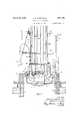
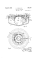
- Fig. 1 is a central vertical section of one form of our improved electrolytic apparatus, and specifically of a cell for the electrolytic production of magnesium;
- Fig. 2 is a plan view of such apparatus or cell with certain of the superstructure removed;
- Fig. 3 is a centralvertical section similar to that of Fig. 1, but looking in the opposite direction, as indicated b the broken line 3-1.
- composition of the bath to be electrolyzed will of course vary in the first place with the metal which it is desired to produce and in the second place, articularly in the electrolytic production of magnesium, as is well known, several different salts or compounds are available from which a selection may be made.
- the present apparatus while designed more particularly for the electrolysis of magnesium chloride is, it will be understood, adaptable for general use in thus producing so-called light metals from their chlorides or other compounds.
- the molten bath is'contained in a metallic vessel 1, which, as shown in the several figures of the drawings, preferably takes the form of a relatively shallow cast steel pot of approximately. circular form in plan, such vessel being provided with an outwardly directed flange 2 about its upper edge, whereby the vessel may be supported on the walls 3 of a suitable furnace chamber, such furnace being required to produce initial fusion of the electrolyte,.or to warm up, in case of necessity, the contents of the pot.
- a metallic vessel 1 which, as shown in the several figures of the drawings, preferably takes the form of a relatively shallow cast steel pot of approximately. circular form in plan, such vessel being provided with an outwardly directed flange 2 about its upper edge, whereby the vessel may be supported on the walls 3 of a suitable furnace chamber, such furnace being required to produce initial fusion of the electrolyte,.or to warm up, in case of necessity, the contents of the pot.
- the sidewall of the pot is formed wit an integral upwardly projecting arm 4, through which electric current. may be supplied to the pot by means of suitable connections, as will be presently described, such pot serving as the main cathode member of the cell.
- an openended cylindrical s ell or curtain ring 5 that constitutes a suiplemental cathode member to the vessel.
- uch shell or ring 5 is provided with feet 6, or equivalent means whereby it isheld in spaced relation from the bottom of the pot or vessel 1, so that the electrolyte may circulate freely withinand about the shell, such feet being preferabl welded to the ot bottom.
- the upper end 6 ring 5 is slightl y contracted so as to form a neck or well 7 of somewhat reduced diameter in which the molten metal may collect, such well rising above the level of the electrolyte in vesrsel land being fitted with a removable cover of the pot and the outer surface of the ring form respectively the outer and inner active cathode surfaces of an enclosed annular ring shaped cell, in which also a plurality of anodes, as will presently be described, depend from above into the electrolyte.
- the vessel 1 is provided with an inwardly directed flange 12 and supported on the latter is an annular ring 14 of refractory material, a ring 15 of similar material but of smaller diameter resting on the offset portion of shell 5 formed by the necking in of the latter. Additional courses 16 and 17 of refractory material may be built upon said rings 14 and 15 to provide a support for an annular cover 18 that closes the portion of the pot or vessel 1 lying between the outer wall thereof, and the shell 5.
- This cover as best shown in Fig. 2 is preferably composed of segmental sections 18 which are parted on lines intersecting the positions of the series of carbon electrodes 20 that constitute the anode members of the cell.
- the central opening left by such annular cover is adapted to be closed by a separate removable cover 21 'located directly over the cover 8 on the cathode ring or shell 5.
- the number of carbon electrodes 20 will of course vary with the size of the cell, fourteen being employed in the particular one illustrated in the drawings, such electrodes being supported so as to depend downwardly into the space between the outer wall of vessel 1 and the shell or ring 5.
- a corresponding number of hanger rods 22 are vertically guided in a suitable frame 23 supported at a suitable height above the cell-byposts 24, caps 25 of insulating material being interposed between such posts and frame so that the latter will be thoroughly. insulated from the cell and avoid grounding.
- the rods 22 at their lower ends are provided with clamps 26 whereby they may be detachably secured to the adjacent ends of the corresponding electrodes 20 and provision is made for raising and lowering the latter by means of a series of winches 27, one for each rod or electrode, such winches being connected with the several clamps 26 through the medium of cables orchains 28.
- Each winch is independently operable by means of worm gearing 28 and a detachable crank 29 so that any selected electrode may be raised or lowered in order to cause such' electrode to depend the proper distance into vessel 1.
- the electrical connections for the electrodes 20 include a common circular buss bar 30 that surrounds the rods 22, and flexible leads 31 extending from such bar to the respective clamps 26. Only two such leads are shown in Fig. 1, just as only one of the winches is there shown in order not to confuse the drawings with unnecessary details.
- the anodes 20 occupy a part only of'the annular space, being disposed in a horseshoe shaped formation, soas to leave a space 35 (see Fig. 2) that may be denominated a neutral zone.
- the approximate level of the electrolyte is shown by the line aa in Fig. 3.
- Metallic collecting rings 36 and 37 skirt the upper edges respectively of the outer and inner active cathode surfaces, these rings being in effect parts of the inner and outer cathodes that depend. into the cell both in the form of inverted troughs, adapted to catch and collect the metal risingthrough the bath from the cathode surfaces by gravity.
- troughs are connected by ports 38 and a duct 39 to the inner collecting well 7, said ports and ducts being adapted to lead the metal from the collecting troughs into the well, where it may accumulate to a considerable depth, enabling easy withdrawal at suitable intervals of time.
- Cathodic action upon metallic surfaces above these collecting rings is restricted and practically prevented by the covering rings 14 and 15, which as previously described may be of fire brick or other suitable material and are fitted upon such surfaces thereby protecting them from the action of the anolyte and anode products as well as reducing the flow of current and production of metal above the collecting rings.
- the covers 18 may be made from soapstone slabs or the like and are closely fitted around the anodes as well as rest closely upon the brick or equivalent rings 16 and 17, thereby forming together with baflles 40 and 41 that dip into the; electrolyte and cross the annular ring shaped space between the ends of the neutral zone 35 (see Fig.2) and theends of the horseshoe shaped anode compartment, a closed anode gas trap above the electrolyte.
- Such trapped space is provided with an outlet 42 through one of the covers suited for connection to a fine for drawing oif obnoxious or valuable gaseous anode products.
- The'protective rings covering the upper metal surfaces in contact with the anolyte prevent any substantial flow of current throu h the bath to such surfaces, thereby restrictmg the liberation of metal thereon to a negligible amount, and these rings also cover and protect those metal surfaces from the corrosive action of the anolyte and anode products.
- the covers 21 and 8 may be removed, access being easy thereto through the space between the'ends of the horseshoe shaped ring of anodes and over the neutral zone 35, and the metal may be dipped out, tapped or drawn off by gravity or b suction through a pipe.
- sludge or sediment may be withdrawn through such neutral zone and, if the chloride fed to the cell be anhydrous, fresh electrolyte may be added therethrough. If, however, MgCl .H,(), or similar chloride containing water of crystallization be used, we
- This cell will be found well adapted to the production of metals which will float upon a fused bath, the specific form illustrated being admirably suited to the production of metallic magnesium from a fused chloride bath.
- This cell employs a cathode pot and central cathode ring instead of the conventional cathode pot only. It further employs a plurality of anodes arranged in'a ring in the annular cell enclosed between the opposed cathode surfaces of the pot and ring, instead of the single central anode of the conventional cell. In this way possible anode surface and working capacity relative to size and cost of cell are reatly increased, while at the same time a s ort path through the bath, ample cathode surface and low current densit are provided. These features all tend to owervoltage and power. input per unit output.
- Efi'ective conservation of the metal anolyte and anode product attack results from provision made to lead it away promptly to a collect-ing well, where it may stratify free from flux and in a deep layer enabling easy removal at infrequent intervals and safe retention between times of removal; while in the neutral zone workable access is afforded to i. the cell for feeding, stirring if required, removal of bath .or sediment, observation, etc., during operation without requiring interferences with same or making a nuisance through venting of noxious gases, or wastage of valuable heat.
- a vessel adapted to contain such electrolyte in.molten state
- a cathode in the form of a ring supported in said vessel, said ring being arranged to permit free flow of the electrolyte around the lower edge thereof, and being further provided with ports in its upper portion permitting flow of molten metal from without into such portion, and a plurality of anodes depending into said vessel aroundsaid ring.
- a cathode in the form of a ring supported in said vessel said ring being arranged to permit free flow of the electrolyte around the lower edge thereof, and being further provided exterlorly with a downwardly directed trough adjacent to its upper end and with ports from such trough permitting flow of molten metal from without into such upper end, and a plurality of anodes depending into said vessel around said ring.
- An electrolytic cell including an outer cathode pot and an inner cathode ring, and a plurality of anodes depending into the space between said pot and ring, said anodes being omitted at one side to leave a neutral space and permit access to said ring.
- An electrolytic cell including an outer cathode pot and an inner cathode ring, and a lurality of anodes depending into the'space V etween said pot and ring, said anodes being omitted at one side to leave a neutral space and permit access to said ring, and the portion of such space wherein said anodes thus depend being sealed off to form a gas trap.
- An electrolytic cell for producing a molten metal lighter than the electrolyte including an outer cathode pot and an inner cathode ring, a plurality of anodes depending into the space between said pot and ring, and means adapted to collect and conduct molten metal from the exterior of said ring into the interior thereof.
- An electrolytic cell including an outer cathode pot and an inner cathode ring, a plurality of anodes depending into the space between said pot and ring, and a protective covering for the upper portions of. the pot and ring surfaces facing said anodes.
- an electrolytic apparatus for producing a metal lighter than the electrolyte, the combination of a vessel adapted to contain such electrolyte in molten state and constituting the main cathode member, a supplemental cathode in the form of a ring supported in said vessel in spaced relation to the bottom thereof, a plurality of anodes depending into said vessel around said ring, common electrical connections for said vessel and ring, and
- an electrolytic apparatus for producing a metal lighter than the electrolyte, the combination of a vessel adapted to contain such electrolyte in molten state and constituting the main cathode member, a supplemental cathode in'the form of a ring supported in said vessel in spaced relation to the bottom thereof, said ring having its upper portion of reduced diameter whereby a well is formed for collection of molten metal and being further provided with ports adjacent such portion of reduced diameter permitting flow of such metal into such well, a plurality of anodes depending into said vessel around said ring, common electrical connections for said vessel and ring,'and other common electrical connections for said anodes.
- anelectrolytic apparatus for producing a metal lighter than the electrolyte the combination of a vessel adapted to contain such electrolyte in molten state and constituting the main cathode member, a supplemental cathode in the form of a ring supported in said vessel in spaced relation to the bottom thereof, said ring having its upper portion of reduced diameter-whereby a well is formed for collection of molten metal and being further provided exteriorly with'a downwardly directed trough adjacent such portion of reduced diameter and with ports from such trough permitting flow of such metal into such well, a plurality of anodes depending into said vessel around said ring,
- a vessel adapted to contain such electrolyte in molten state and constituting the main cathode member a sup-. plemental cathode in the form of a ring supported in said vessel in spaced relation to the bottom thereof, said ring having its upper portion of reduced .diameter whereby a well is formed for collection of molten metal and being further provided exteriorly with a downwardly directed trough adjacent such portion of reduced diameter and with ports from such trough permitting flow of such metal into such well, a similar trough provided interiorlv of said vessel adjacent its upper end, a duct leading from such lastmentioned trough to such well, a plurality of anodes depending into said vessel around said ring, common electrical connections for said vessel and ring, and other common electrical connections for said anodes.
- tain such electrolyte in molten state
- a cathode in the form of a ring supported in said vessel, said ring being arranged to permit free do of the electrolyte around the lower edge thzi'eof
- an annular cover over the portion of said vessel between the outer wall thereof and said ring, and a plurality of anodes depending through said cover into said vessel around said ring, said cover comprising segmental sections parted on line with said anodes, respectively.
- a vessel adapted to contain such electrolyte in molten state and constituting the main cathode member.
- a supplemental cathode in'the form of a ring supported in said vessel in spaced relation to the bottom thereof, a plurality of anodes depending into said vessel, around said ring, common electrical connections for said vessel and ring, and other common electrical connections for said anodes, saidanodes be-' mg omltted at one side to leave aineutral space and permit access to said ring.
- an electrolytic apparatus for pro ducing a metal lighter than the electrolyte, the combination of a vessel adapted to contain such electrolyte in molten state and constituting the main cathode fnember, a supplemental cathode in the form of a ring supported in said vessel in spaced relation to the bottom thereof, a plurality of anodes de pending into said vessel around said ring, common electrical connections for said vessel and ring, and other common electrical connections for said anodes, the portion of said vessel into which said anodes thus depend being sealed off to form a gas trap.
- an electrolytic apparatus for roducing a metal lighter than the electro yte, the combination of a Vessel adapted to contain such electrolyte in molten state and constituting the main cathode member, a supplemental cathode in the form of a ring supported in said vessel in spaced relation to the bottom thereof, a plurality of anodes depending into said vessel around said ring, common electrical connections for said vessel and ring, and other common electrical connections for said anodes, said anodes being omitted at one side to leave a neutral space and permit access to said ring, and the portion of said vessel into which said anodes thus depend being sealed 03 to, form a gas tra 1%.
- an electrolytic apparatus for producing ametal lighter than the electrolyte, the combination of a vessel adapted to contain such electrolyte in molten state and co stituting the main cathodeamember, a supplemental cathode in the form of a ring supported in said vessel in spaced relation to the bottom thereof, means adapted to collect and conduct molten metal from the exterior' wall of said rin into the interior thereof, a plurality of anodes depending into said vessel ,around said ring, common electrical connections for said vessel and ring, and other common electrical connections for said anodes.
- anelectrolytic apparatus for producing a metal lighter than the electrolyte the combination of-a vessel adapted to contain such electrolyte in molten state, a cathode in the form of a ring supported in said vessel, said ring being arranged to permit free flow oftheelectrolyte around the lower edge thereof, a frame above said vessel, and a plurality of anodes supported from said frame and depending into said vessel around said ring.
- an electrolytic apparatus for producing a metal lighter than the electrolyte the combination of avessel adapted to contain such electrolyte in molten state, a cathode in the form of a ring supported in sand vessel, said ring being arranged to permlt free flow of the electrolyte around the lower edge thereof, a frameabove said vessel, a plurality of anodes supported from said frame and depending into said vessel around said ring and means adapted to raise and lower said anodes independently.
- an electrolytic apparatus for producing a metal lighter then the electrolyte, the combination of a vessel adapted to contain such electrolyte in molten state, a-cathode in the form of a ring supported in said; vessel, said ring being arranged to permit free flow of the electrolyte around the lower edge thereof, a frame above said vesel, a plurality of anodes supported from said frame and depending into said vessel around said ring, means adapted to raise and lower said anodes independently, common electrical connections for said vessel and said cathode, and other electrical connections to each anode.
- an electrolytic apparatus for producing a metal lighter than the electrolyte
- an electrolytic apparatus for producing a metal lighter than the electrolyte the combination of a vessel adapted to contain such electrolyte in molten state and constituting the principal cathode member, a suppleme'ntal hollow cathode member supported in said vessel in spaced relation from the bottom thereof and forming a oollectin well for the metal produced in the electrolysis, the inner surface of said vessel and the outer surface of said hollow cathode being rovided with a downwardly directed troughike projection at the u per end of the active portion thereof adapte to entrap molten metal rising from such active cathode surfaces, means for conducting molten metal from said troughs into said collecting well, a lurality of anodes depending into the space tween said vessel and supplemental cathode, common electrical connections for said principal and supplemental cathodes and other common electrical connections for said anodes.
- an electrolytic apparatus for producing a metal lighter than the electrolyte the combination of a vessel adapted to contain such electrolyte in molten state and constituting the principal cathode member, a supple mental hollow cathode member supported in said vessel in spaced relation from the bottom thereof, a plurality of anodes depending into the space between said vessel and supplemental cathode, common electrical connections for said principal and supplemental cathodes and other common electrical connections for said anodes.
- an electrolytic apparatus for producing a metal lighter than the electrolyte the combination of a vessel adapted to contain such electrolyte in molten state and constituting the principal cathode member, a supplemental hollow cathode meinber supported in said vessel in spaced relation from the bottom thereof, the inner surface of said vessel and the outer surface of said hollow cathode being provided with a downwardly directed trough-like projection at the upper end of the active portion thereof adapted to collect mol
Landscapes
- Chemical & Material Sciences (AREA)
- Engineering & Computer Science (AREA)
- Chemical Kinetics & Catalysis (AREA)
- Electrochemistry (AREA)
- Materials Engineering (AREA)
- Metallurgy (AREA)
- Organic Chemistry (AREA)
- Electrolytic Production Of Metals (AREA)
Description
March 29, 1932.
L. E. WARD ET AL ELECTROLYTIC APPARATUS Filed Aug. 5. 1927 2 sneets-sneet INVENTORS 1.014215 5. Marc/ and 3 M T a;
3617,2777 777. Hunter A TTORNEYS March 29, L WAR ET AL ELECTROLYT I C APPARATUS Filed Aug. 5, 1927 2 Sheets-Sheet 2 b 35 7 1 g l l l. I \,h I g n I /l -1: I I m a l W. I. METAL METAL. i 3b 99, a "is OUTER BATH 5 BATH (,ATHODE W Q6 21 Q i;
INVENTOR.) 9
Q0206 c5. Zd'arc/ k; BY 71 456 2 77f flu fer I 0% b Q94? ATTORNEY6.
Patented Mar. 29, 1932 UNITED STATES PATENT OFFICE LOUIS E. WARD AND RALPH M. HUNTER, OF MIDLAND, MICHIGAN, ASSIGNORS TO THE DOW CHEMICAL COMPANY, OF MIDLAND, MICHIGAN, A CORPORATION 01' MICHIGAN ELECTROLYTIC APPARATUS Application filed August 5, 1927.- Serial No. 210,785.-
The present improvements, relating as indicated to electrolytic apparatus, have more particular regard to an electrolytic cell for roducing a metal lighter than the electroyte, for example for producing metallic magnesium from a bath of molten salts or compounds of such metal and specifically from magnesium chloride. In the operation of a so-called magnesium cell various difficulties are encountered due not onl to the fact that the metal is lighter than t e bath but also due to the fact that such metal when highly heated i. e. in fluid state, readily ignites or burns upon exposure to the air. It
. isalso diflicult to collect the dispersed particle of the metal free from adhering electrolyte.
One object of the resent invention ac-. cordingly is to provi e an electrolytic apparatus or cell so arranged as to permit the easy and convenient addition of fresh raw material to the cell as well as the collection and removal therefrom of the molten metal with minimum danger of the latter being oxidized. A further object is to provide an apparatus or cell which may be constructed as a large unit, which will have a considerably greater capacity than an such apparatus heretofore desl ed, so ar as we are aware, and which Wlll be capable of continuous'operation, i. e. without requiring to be shut down incidentally to charging raw material or removi metal product or even for replacing the car on electrodes employed as anodes in the cell. 7
To the accomplishment of the foregoing and related ends the invention then consists of the. means'hereinafter fully described and particularly pointed out in the claims,-the annexed drawings and the following description illustrating but-one of the various ways in which the principle of the invention may a be carried out;
In said annexed drawin s:
Fig. 1 is a central vertical section of one form of our improved electrolytic apparatus, and specifically of a cell for the electrolytic production of magnesium; Fig. 2 is a plan view of such apparatus or cell with certain of the superstructure removed; and Fig. 3 is a centralvertical section similar to that of Fig. 1, but looking in the opposite direction, as indicated b the broken line 3-1.
The composition of the bath to be electrolyzed will of course vary in the first place with the metal which it is desired to produce and in the second place, articularly in the electrolytic production of magnesium, as is well known, several different salts or compounds are available from which a selection may be made. The present apparatus while designed more particularly for the electrolysis of magnesium chloride is, it will be understood, adaptable for general use in thus producing so-called light metals from their chlorides or other compounds.
The molten bath is'contained in a metallic vessel 1, which, as shown in the several figures of the drawings, preferably takes the form of a relatively shallow cast steel pot of approximately. circular form in plan, such vessel being provided with an outwardly directed flange 2 about its upper edge, whereby the vessel may be supported on the walls 3 of a suitable furnace chamber, such furnace being required to produce initial fusion of the electrolyte,.or to warm up, in case of necessity, the contents of the pot.
At one point in its periplhery the sidewall of the pot is formed wit an integral upwardly proiecting arm 4, through which electric current. may be supplied to the pot by means of suitable connections, as will be presently described, such pot serving as the main cathode member of the cell. Supported cen trally within the ot or vessel. is an openended cylindrical s ell or curtain ring 5, that constitutes a suiplemental cathode member to the vessel. uch shell or ring 5 is provided with feet 6, or equivalent means whereby it isheld in spaced relation from the bottom of the pot or vessel 1, so that the electrolyte may circulate freely withinand about the shell, such feet being preferabl welded to the ot bottom. The upper end 6 ring 5 is slightl y contracted so as to form a neck or well 7 of somewhat reduced diameter in which the molten metal may collect, such well rising above the level of the electrolyte in vesrsel land being fitted with a removable cover of the pot and the outer surface of the ring form respectively the outer and inner active cathode surfaces of an enclosed annular ring shaped cell, in which also a plurality of anodes, as will presently be described, depend from above into the electrolyte. In addition to the outwardly projecting flange 2 the vessel 1 is provided with an inwardly directed flange 12 and supported on the latter is an annular ring 14 of refractory material, a ring 15 of similar material but of smaller diameter resting on the offset portion of shell 5 formed by the necking in of the latter. Additional courses 16 and 17 of refractory material may be built upon said rings 14 and 15 to provide a support for an annular cover 18 that closes the portion of the pot or vessel 1 lying between the outer wall thereof, and the shell 5. This cover as best shown in Fig. 2 is preferably composed of segmental sections 18 which are parted on lines intersecting the positions of the series of carbon electrodes 20 that constitute the anode members of the cell. The central opening left by such annular cover is adapted to be closed by a separate removable cover 21 'located directly over the cover 8 on the cathode ring or shell 5. v
The number of carbon electrodes 20 will of course vary with the size of the cell, fourteen being employed in the particular one illustrated in the drawings, such electrodes being supported so as to depend downwardly into the space between the outer wall of vessel 1 and the shell or ring 5.
For the purpose of thus supporting the electrodes 20 a corresponding number of hanger rods 22 are vertically guided in a suitable frame 23 supported at a suitable height above the cell-byposts 24, caps 25 of insulating material being interposed between such posts and frame so that the latter will be thoroughly. insulated from the cell and avoid grounding. The rods 22 at their lower ends are provided with clamps 26 whereby they may be detachably secured to the adjacent ends of the corresponding electrodes 20 and provision is made for raising and lowering the latter by means of a series of winches 27, one for each rod or electrode, such winches being connected with the several clamps 26 through the medium of cables orchains 28. Each winch is independently operable by means of worm gearing 28 and a detachable crank 29 so that any selected electrode may be raised or lowered in order to cause such' electrode to depend the proper distance into vessel 1.
The electrical connections for the electrodes 20 include a common circular buss bar 30 that surrounds the rods 22, and flexible leads 31 extending from such bar to the respective clamps 26. Only two such leads are shown in Fig. 1, just as only one of the winches is there shown in order not to confuse the drawings with unnecessary details.
It will be noted that the anodes 20 occupy a part only of'the annular space, being disposed in a horseshoe shaped formation, soas to leave a space 35 (see Fig. 2) that may be denominated a neutral zone. The approximate level of the electrolyte is shown by the line aa in Fig. 3. Metallic collecting rings 36 and 37 skirt the upper edges respectively of the outer and inner active cathode surfaces, these rings being in effect parts of the inner and outer cathodes that depend. into the cell both in the form of inverted troughs, adapted to catch and collect the metal risingthrough the bath from the cathode surfaces by gravity. These troughs are connected by ports 38 and a duct 39 to the inner collecting well 7, said ports and ducts being adapted to lead the metal from the collecting troughs into the well, where it may accumulate to a considerable depth, enabling easy withdrawal at suitable intervals of time. Cathodic action upon metallic surfaces above these collecting rings is restricted and practically prevented by the covering rings 14 and 15, which as previously described may be of fire brick or other suitable material and are fitted upon such surfaces thereby protecting them from the action of the anolyte and anode products as well as reducing the flow of current and production of metal above the collecting rings.
The covers 18 may be made from soapstone slabs or the like and are closely fitted around the anodes as well as rest closely upon the brick or equivalent rings 16 and 17, thereby forming together with baflles 40 and 41 that dip into the; electrolyte and cross the annular ring shaped space between the ends of the neutral zone 35 (see Fig.2) and theends of the horseshoe shaped anode compartment, a closed anode gas trap above the electrolyte. Such trapped space is provided with an outlet 42 through one of the covers suited for connection to a fine for drawing oif obnoxious or valuable gaseous anode products.
Cover 8, it will be noted, seals in the bath "and retains a reducing atmosphere above the pot at or near the center. The bath ma be stirred through this zone and opening i desired. The baflles 40 and 41 restrict circulation of anolyte into this neutral zone 35.
In operation, electric current leaving the anodes passes from them to the cathode surfaces in generally radial directions outwardly and inwardly, through the bath, liberate ing and depositing metal upon the vertical cathode surfaces. This metal as soon as it imcumulates in sufliciently large droplets or films rises by reason of its low gravity and is caught in the collecting rings, from WhlCll it is led by the duct 39 from the collecting ring 36 and the ports 38 from the collectin ring 37 into the central metal collecting well The aseous anode products, as for instance chlorine and hydrochloric acid (the latter if some water be present in the bath) are trapped as hereinbefore described and are led off for use or other disposal through the outlet 42. The'protective rings covering the upper metal surfaces in contact with the anolyte prevent any substantial flow of current throu h the bath to such surfaces, thereby restrictmg the liberation of metal thereon to a negligible amount, and these rings also cover and protect those metal surfaces from the corrosive action of the anolyte and anode products.
At suitable intervals, the covers 21 and 8 may be removed, access being easy thereto through the space between the'ends of the horseshoe shaped ring of anodes and over the neutral zone 35, and the metal may be dipped out, tapped or drawn off by gravity or b suction through a pipe. At other suitab e intervals, sludge or sediment may be withdrawn through such neutral zone and, if the chloride fed to the cell be anhydrous, fresh electrolyte may be added therethrough. If, however, MgCl .H,(), or similar chloride containing water of crystallization be used, we
refer to feed it into the anode compartment in accordance with the method specified in U. S. Letters Patent to Cottringer and Heath U. S. 1,567,318, dated Dec. 29, 1225, covering use of hydrated feeds. The bath may also be dipped out or drawn out through the neutralr zone. If desired a notch 43 (see Fig. 3) may be left in the cathode ring 5 adjacent to the neutral zone to make easier access of dipper to inner portions of the bath.
This cell will be found well adapted to the production of metals which will float upon a fused bath, the specific form illustrated being admirably suited to the production of metallic magnesium from a fused chloride bath. This cell employs a cathode pot and central cathode ring instead of the conventional cathode pot only. It further employs a plurality of anodes arranged in'a ring in the annular cell enclosed between the opposed cathode surfaces of the pot and ring, instead of the single central anode of the conventional cell. In this way possible anode surface and working capacity relative to size and cost of cell are reatly increased, while at the same time a s ort path through the bath, ample cathode surface and low current densit are provided. These features all tend to owervoltage and power. input per unit output.
Efi'ective conservation of the metal anolyte and anode product attack results from provision made to lead it away promptly to a collect-ing well, where it may stratify free from flux and in a deep layer enabling easy removal at infrequent intervals and safe retention between times of removal; while in the neutral zone workable access is afforded to i. the cell for feeding, stirring if required, removal of bath .or sediment, observation, etc., during operation without requiring interferences with same or making a nuisance through venting of noxious gases, or wastage of valuable heat.
Small modifications will permit use of the i neutral zone for a metal collecting well, i. e. by directing the outlets from the collecting rings into same. We accordingly do not limit ourselves to exact details as shown or to strictly concentric or circular constructions, since many of the advantages of the double cathode and .ring of anodes may be attained using rectangular, oval, triangular and other geometric or irregular forms, the circular form being, however, a convenient one.
Other modes of applying the principle of our invention may be employed instead of the one explained, change being made as regards the mechanism herein disclosed, provided the means stated by any of the following claims or the equivalent of such stated means be employed.
We therefore particularly point out and distinctly claim 'as our invention 1. In an electrolytic apparatus for producing a metal lighter than the electrotlye, the
combination of a vessel adapted to contain such electrolyte in.molten state, a cathode in the form of a ring supported in said vessel, said ring being arranged to permit free flow of the electrolyte around the lower edge thereof, and being further provided with ports in its upper portion permitting flow of molten metal from without into such portion, and a plurality of anodes depending into said vessel aroundsaid ring.
- 2. In an electrolytic apparatus for producing a metal lighter than the electrolyte, the
combination of a vessel adapted to contain,
such electrolyte in molten state, a cathode in the form of a ring supported in said vessel, said ring being arranged to permit free flow of the electrolyte around the lower edge thereof, and being further provided exterlorly with a downwardly directed trough adjacent to its upper end and with ports from such trough permitting flow of molten metal from without into such upper end, and a plurality of anodes depending into said vessel around said ring.
3. An electrolytic cell including an outer cathode pot and an inner cathode ring, and a plurality of anodes depending into the space between said pot and ring, said anodes being omitted at one side to leave a neutral space and permit access to said ring.
4. An electrolytic cell including an outer cathode pot and an inner cathode ring, and a lurality of anodes depending into the'space V etween said pot and ring, said anodes being omitted at one side to leave a neutral space and permit access to said ring, and the portion of such space wherein said anodes thus depend being sealed off to form a gas trap.
5. An electrolytic cell for producing a molten metal lighter than the electrolyte, including an outer cathode pot and an inner cathode ring, a plurality of anodes depending into the space between said pot and ring, and means adapted to collect and conduct molten metal from the exterior of said ring into the interior thereof. I
6. An el ctrolytic cell for producing a molten meta lighter than the electrolyte, in-
eluding an outer cathode pot and an inner cathode ring, a plurality of anodes depending into the space between said pot and ring, and means adapted to collect and conduct molten metal from the collecting troughs adjacent the interior wall of said pot and the exterior wall of said ring, respectively, into the interior of said ring. l
7. An electrolytic cell including an outer cathode pot and an inner cathode ring, a plurality of anodes depending into the space between said pot and ring, and a protective covering for the upper portions of. the pot and ring surfaces facing said anodes.
8. In an electrolytic apparatus for producing a metal lighter than the electrolyte, the combination of a vessel adapted to contain such electrolyte in molten state and constituting the main cathode member, a supplemental cathode in the form of a ring supported in said vessel in spaced relation to the bottom thereof, a plurality of anodes depending into said vessel around said ring, common electrical connections for said vessel and ring, and
' mental cathode in the form of a ring supported in said vessel in spaced relation to the bottom thereof, said ring having, its upper portion ofgreduced diameter whereby a well is formed for collection of molten metal, a plurality of anodes depending into said vessel 4 around said ring, common electrical connecanon electrical connections for said anodes.
10. In an electrolytic apparatus for producing a metal lighter than the electrolyte, the combination of a vessel adapted to contain such electrolyte in molten state and constituting the main cathode member, a supplemental cathode in'the form of a ring supported in said vessel in spaced relation to the bottom thereof, said ring having its upper portion of reduced diameter whereby a well is formed for collection of molten metal and being further provided with ports adjacent such portion of reduced diameter permitting flow of such metal into such well, a plurality of anodes depending into said vessel around said ring, common electrical connections for said vessel and ring,'and other common electrical connections for said anodes.
all. In anelectrolytic apparatus for producing a metal lighter than the electrolyte, the combination of a vessel adapted to contain such electrolyte in molten state and constituting the main cathode member, a supplemental cathode in the form of a ring supported in said vessel in spaced relation to the bottom thereof, said ring having its upper portion of reduced diameter-whereby a well is formed for collection of molten metal and being further provided exteriorly with'a downwardly directed trough adjacent such portion of reduced diameter and with ports from such trough permitting flow of such metal into such well, a plurality of anodes depending into said vessel around said ring,
common electrical connections 'for said vessel and ring, and other common electrical connections for said anodes.
12. In an electrolytic apparatus for producing a metal lighter than the electrolyte,
the combination of a vessel adapted to contain such electrolyte in molten state and constituting the main cathode member, a sup-. plemental cathode in the form of a ring supported in said vessel in spaced relation to the bottom thereof, said ring having its upper portion of reduced .diameter whereby a well is formed for collection of molten metal and being further provided exteriorly with a downwardly directed trough adjacent such portion of reduced diameter and with ports from such trough permitting flow of such metal into such well, a similar trough provided interiorlv of said vessel adjacent its upper end, a duct leading from such lastmentioned trough to such well, a plurality of anodes depending into said vessel around said ring, common electrical connections for said vessel and ring, and other common electrical connections for said anodes.
13. In an electrolytic apparatus for producing a metal lighter than the electrolyte, the combination of a'vessel adapted to contain such electrolyte in molten state, a cathode in the form of a ring supported in said the combination of a Vessel adapted to con-,
, depending through said cover into said vessel around said ring, and a separate centrally located cover for said vessel directly over said ring.
14. In an electrolytic apparatus for pro-' ducing a metal lighter than the electrolyte,
the combination of a vessel adapted to contain such electrolyte in molten state, a cathode in the form of a ring supported in said vessel, said ring being arranged to permit free flow of the electrolyte around the lower edge thereof, an annular cover over the portion ofsaid vessel between the outer wall thereof and said ring, a plurality of anodes depending through said cover into said vessel around said ring, a separate centrally located cover for said vessel directly over said ring, and an independent cover for the latter. 15. In an electrolytic apparatus for producing a metal lighter than the electrolyte,
tain such electrolyte in molten state, a cathode in the form of a ring supported in said vessel, said ring being arranged to permit free do of the electrolyte around the lower edge thzi'eof, an annular cover over the portion of said vessel between the outer wall thereof and said ring, and a plurality of anodes depending through said cover into said vessel around said ring, said cover comprising segmental sections parted on line with said anodes, respectively.
16. In an electrolytic apparatus for producing .a metal lighter than the electrolyte, the combinationof a vessel adapted to contain such electrolyte in molten state and constituting the main cathode member. a supplemental cathode in'the form of a ring supported in said vessel in spaced relation to the bottom thereof, a plurality of anodes depending into said vessel, around said ring, common electrical connections for said vessel and ring, and other common electrical connections for said anodes, saidanodes be-' mg omltted at one side to leave aineutral space and permit access to said ring.
17. In an electrolytic apparatus for pro ducing a metal lighter than the electrolyte, the combination of a vessel adapted to contain such electrolyte in molten state and constituting the main cathode fnember, a supplemental cathode in the form of a ring supported in said vessel in spaced relation to the bottom thereof, a plurality of anodes de pending into said vessel around said ring, common electrical connections for said vessel and ring, and other common electrical connections for said anodes, the portion of said vessel into which said anodes thus depend being sealed off to form a gas trap.
18. In an electrolytic apparatus for roducing a metal lighter than the electro yte, the combination of a Vessel adapted to contain such electrolyte in molten state and constituting the main cathode member, a supplemental cathode in the form of a ring supported in said vessel in spaced relation to the bottom thereof, a plurality of anodes depending into said vessel around said ring, common electrical connections for said vessel and ring, and other common electrical connections for said anodes, said anodes being omitted at one side to leave a neutral space and permit access to said ring, and the portion of said vessel into which said anodes thus depend being sealed 03 to, form a gas tra 1%. In an electrolytic apparatus for producing ametal lighter than the electrolyte, the combination of a vessel adapted to contain such electrolyte in molten state and co stituting the main cathodeamember, a supplemental cathode in the form of a ring supported in said vessel in spaced relation to the bottom thereof, means adapted to collect and conduct molten metal from the exterior' wall of said rin into the interior thereof, a plurality of anodes depending into said vessel ,around said ring, common electrical connections for said vessel and ring, and other common electrical connections for said anodes.
20. In an electrolytic apparatus for. roducing a metal lighter than the electro yte, the combination of a vessel adapted to contain such electrolyte in molten state and constituting the mam cathode member, asupplemental cathode in the form of a mug sup.-
ported in said vessel in spaced relation to v said ring, respectively, into the interior of said ring, a plurality of anodes depending into-said vessel around said ring, common electrical connections for s'aidvessel and ring, and other common electrical connections for said anodes. j
21. In anelectrolytic apparatus for producing a metal lighter than the electrolyte, the combination of-a vessel adapted to contain such electrolyte in molten state, a cathode in the form of a ring supported in said vessel, said ring being arranged to permit free flow oftheelectrolyte around the lower edge thereof, a frame above said vessel, and a plurality of anodes supported from said frame and depending into said vessel around said ring.
22. In an electrolytic apparatus for producing a metal lighter than the electrolyte, the combination of avessel adapted to contain such electrolyte in molten state, a cathode in the form of a ring supported in sand vessel, said ring being arranged to permlt free flow of the electrolyte around the lower edge thereof, a frameabove said vessel, a plurality of anodes supported from said frame and depending into said vessel around said ring and means adapted to raise and lower said anodes independently.
23. In an electrolytic apparatus for producing a metal lighter then the electrolyte, the combination of a vessel adapted to contain such electrolyte in molten state, a-cathode in the form of a ring supported in said; vessel, said ring being arranged to permit free flow of the electrolyte around the lower edge thereof, a frame above said vesel, a plurality of anodes supported from said frame and depending into said vessel around said ring, means adapted to raise and lower said anodes independently, common electrical connections for said vessel and said cathode, and other electrical connections to each anode.
24. In an electrolytic apparatus for producing a metal lighter than the electrolyte, the combination ofacathodehavingasubstantially vertical active surface and a downwardly directed trough-like projection at the upper part of said active surface to collect molten metal rising therefrom.
25. In an electrolytic apparatus for producing a metal lighter than the electrolyte, the combination of a. vessel adapted to contain such electrolyte in molten state, a hollow cathode member supported in said vessel in spaced relation from the bottom thereof and being provided on the outer surface adjacent to its upper end with a downwardly directed trough-like projection and with ports from such trough permitting flow of molten metal ten metal rising from such active cathode surfaces, a plurality of anodes deipending into the space between said vessel an supplementary cathode, common electrical connections for said principal and supplemental cathodes and other common electrical connections for said anodes.
28. In an electrolytic apparatus for producing a metal lighter than the electrolyte, the combination of a vessel adapted to contain such electrolyte in molten state and constituting the principal cathode member, a suppleme'ntal hollow cathode member supported in said vessel in spaced relation from the bottom thereof and forming a oollectin well for the metal produced in the electrolysis, the inner surface of said vessel and the outer surface of said hollow cathode being rovided with a downwardly directed troughike projection at the u per end of the active portion thereof adapte to entrap molten metal rising from such active cathode surfaces, means for conducting molten metal from said troughs into said collecting well, a lurality of anodes depending into the space tween said vessel and supplemental cathode, common electrical connections for said principal and supplemental cathodes and other common electrical connections for said anodes.
Signed by us this 1st day of August, 1927.
- LOUIS E. WARD.
RALPH M. HUNTER.
therefrom into the interior of said cathode,
and a plurality of anodes depending into, said vessel around said cathode.
26. In an electrolytic apparatus for producing a metal lighter than the electrolyte, the combination of a vessel adapted to contain such electrolyte in molten state and constituting the principal cathode member, a supple mental hollow cathode member supported in said vessel in spaced relation from the bottom thereof, a plurality of anodes depending into the space between said vessel and supplemental cathode, common electrical connections for said principal and supplemental cathodes and other common electrical connections for said anodes.
2'11. In an electrolytic apparatus for producing a metal lighter than the electrolyte, the combination of a vessel adapted to contain such electrolyte in molten state and constituting the principal cathode member, a supplemental hollow cathode meinber supported in said vessel in spaced relation from the bottom thereof, the inner surface of said vessel and the outer surface of said hollow cathode being provided with a downwardly directed trough-like projection at the upper end of the active portion thereof adapted to collect mol
Priority Applications (1)
| Application Number | Priority Date | Filing Date | Title |
|---|---|---|---|
| US210785A US1851789A (en) | 1927-08-05 | 1927-08-05 | Electrolytic apparatus |
Applications Claiming Priority (1)
| Application Number | Priority Date | Filing Date | Title |
|---|---|---|---|
| US210785A US1851789A (en) | 1927-08-05 | 1927-08-05 | Electrolytic apparatus |
Publications (1)
| Publication Number | Publication Date |
|---|---|
| US1851789A true US1851789A (en) | 1932-03-29 |
Family
ID=22784247
Family Applications (1)
| Application Number | Title | Priority Date | Filing Date |
|---|---|---|---|
| US210785A Expired - Lifetime US1851789A (en) | 1927-08-05 | 1927-08-05 | Electrolytic apparatus |
Country Status (1)
| Country | Link |
|---|---|
| US (1) | US1851789A (en) |
Cited By (3)
| Publication number | Priority date | Publication date | Assignee | Title |
|---|---|---|---|---|
| US2424179A (en) * | 1941-10-15 | 1947-07-15 | Robert J Mcnitt | Method and apparatus for purifying a molten light metal by precipitation of impurities |
| US2484068A (en) * | 1943-03-11 | 1949-10-11 | Mallory & Co Inc P R | Electrodeposition apparatus |
| US3071532A (en) * | 1959-12-07 | 1963-01-01 | Ciba Ltd | Cells for the electrolysis of fused salts |
-
1927
- 1927-08-05 US US210785A patent/US1851789A/en not_active Expired - Lifetime
Cited By (3)
| Publication number | Priority date | Publication date | Assignee | Title |
|---|---|---|---|---|
| US2424179A (en) * | 1941-10-15 | 1947-07-15 | Robert J Mcnitt | Method and apparatus for purifying a molten light metal by precipitation of impurities |
| US2484068A (en) * | 1943-03-11 | 1949-10-11 | Mallory & Co Inc P R | Electrodeposition apparatus |
| US3071532A (en) * | 1959-12-07 | 1963-01-01 | Ciba Ltd | Cells for the electrolysis of fused salts |
Similar Documents
| Publication | Publication Date | Title |
|---|---|---|
| US2760930A (en) | Electrolytic cell of the diaphragm type | |
| CA1097588A (en) | Flow control baffles for molten salt electrolysis | |
| US4064021A (en) | Method of improving electrolyte circulation | |
| US1851789A (en) | Electrolytic apparatus | |
| US4133727A (en) | Method for extracting heat from a chamber containing a molten salt | |
| US1851817A (en) | Electrolytic apparatus | |
| US2629688A (en) | Electrolytic apparatus for production of magnesium | |
| US1839756A (en) | Method of electrolysis of fused bath and apparatus therefor | |
| US4203819A (en) | Electrolytic cell with flow detection means | |
| US2468022A (en) | Electrolytic apparatus for producing magnesium | |
| US1921377A (en) | Electrolytic apparatus | |
| US2801964A (en) | Cathode assembly for electrolytic cells | |
| US3265606A (en) | Electrolytic cell for preparation of alloys of lead with alkaline metals | |
| US1755380A (en) | Method and means for electrolytic production of light metals | |
| US2291644A (en) | Apparatus for electrolysis of fused electrolytes | |
| JPS5839789A (en) | Electrolyzing method for molten chloride | |
| US2393685A (en) | Electrolytic cell | |
| US2539743A (en) | Electrolytic refining of impure aluminum | |
| US1845266A (en) | Method of segregating light metal floating on fused electrolyte and means therefor | |
| US2552423A (en) | Process for the direct production of refined aluminum | |
| US1074988A (en) | Apparatus for electrolysis of fused alkali chlorids. | |
| US2401821A (en) | Electrolytic cell | |
| US2904491A (en) | Apparatus for producing refractory metal | |
| US1408142A (en) | Electrolytic apparatus | |
| US3118827A (en) | Fused salt electrolysis cell |