US1851779A - Collapsible bow and arrow stand - Google Patents
Collapsible bow and arrow stand Download PDFInfo
- Publication number
- US1851779A US1851779A US426160A US42616030A US1851779A US 1851779 A US1851779 A US 1851779A US 426160 A US426160 A US 426160A US 42616030 A US42616030 A US 42616030A US 1851779 A US1851779 A US 1851779A
- Authority
- US
- United States
- Prior art keywords
- standard
- bow
- arrow
- stand
- collar
- Prior art date
- Legal status (The legal status is an assumption and is not a legal conclusion. Google has not performed a legal analysis and makes no representation as to the accuracy of the status listed.)
- Expired - Lifetime
Links
- 102100023170 Nuclear receptor subfamily 1 group D member 1 Human genes 0.000 description 1
- 241000053208 Porcellio laevis Species 0.000 description 1
- 241000220010 Rhode Species 0.000 description 1
- 230000015572 biosynthetic process Effects 0.000 description 1
- 238000010276 construction Methods 0.000 description 1
- 230000004048 modification Effects 0.000 description 1
- 238000012986 modification Methods 0.000 description 1
Images

Classifications
-
- F—MECHANICAL ENGINEERING; LIGHTING; HEATING; WEAPONS; BLASTING
- F41—WEAPONS
- F41B—WEAPONS FOR PROJECTING MISSILES WITHOUT USE OF EXPLOSIVE OR COMBUSTIBLE PROPELLANT CHARGE; WEAPONS NOT OTHERWISE PROVIDED FOR
- F41B5/00—Bows; Crossbows
- F41B5/14—Details of bows; Accessories for arc shooting
Definitions
- the present invention has as a further object 5 to provide a stand by the use of which a bow may be supported in horizontal position, and a considerable number of arrows may be supported in upright position so that the stand constitutes a means whereby both thebow and arrows may be supported in such position as to be available for use with out the necessity of stooping to pick them from the ground.
- Another object of the invention is to provide an arrow stand so constructed that the standor upright thereof may constitute also a holder or container .for the part of the device which is to support the arrows in upright position, so that the device may be compactly arranged with its parts inknocked-down assembly and carried in the arrow case ordinarily employed and taking up less room than one of the arrows-
- Another object of the invention is to provide a bow stand in which the bow supporting member may be removed from the stand and folded so that the two parts, when notin use, and stored away, will occupy but little space.
- Figure 2 is a horizontal sectional view on the line 22 of Figure 1 looking in the direction indicated by the arrows.
- Figure 3 is a detail vertical sectional View through the standard of the device, the arrow supporting means being housed therein.
- Figure 4 is a detail view in elevation, illustrating one form of how support embodying the invention, the bow supporting unit being shown in full lines in position for use and in dotted lines in .folded position.
- Figure 5 is a vertical sectional View on the line 55 of Figure 4 looking in the direction indicated by the arrows.
- Figure 6 is a plan view illustrating a modified form of bow holder.
- Figure 7 is a view in side elevation of the holder shown in Figure 6.
- the stand embodying the invention comprises a standard which is indicated by the numeral 1, and which is preferably of hollow formation except at its lower end which is pointed or tapered as at 2- to adapt the same to be readily inserted or driven into the ground a sufficient distance to support the standard in upright position.
- the standard is formed, in its upper end, with diametrically oppositely located slots 3, and a cap member which is indicated by the numeral 4, is fitted over this end of the standard and is likewise formed with diametrically oppositely located slots indicated by the numeral 5.
- the device is intended for the support of arrows, and the other for the supportof a bow and, referring firstto the arrow support, the same comprises a leaf spring which is indicated by the numeral 6, and which is provided at one end with a knurled finger knob? which is of a diameter to adapt it to fit within the cap 4.
- the spring 5 is bowed to substantially annular form as shown in Figure 2 and with its end portions overlapped in the manner shown in this figure, the cap member 4 having been removed from the standard 1, and the overlapped portions of the spring are therefore readily insertible in the slots 3.
- the cap t is then fitted to the upper end of the standard and, if necessary,
- the standard 1 is, as before stated, of'liollow form: and-the spring 6 will beformedof awidth slightly less than the interior diameter ofthe: standard, so that the spring, when separatedlfrom-the standard, may he slid into the standard, and the capmember d then ap-- plied to-the-upper end of the standard so as to close this end and likewise anchor thefinger piece?- of the said spring 'llhe bow holder, inthe embodiment shown in Figures 1, 2, d and f the-drawingswom prises a collar 8 which is preferably ofrectangular form and: provided with a bore; 9 whereby it may berslidablyi fitted upon the, standard.
- the arms 11 and" 1 5 areprovided att-hei-r outer ends with right angularly forwardly extending supporting portions indicated respectivel-y'by the numerale-17 and 18, and, each of these portions has its uaper edge of arcuate form, or in. other wor s, curveddownwardly from end to end, as indicated by the numeral 19, so that the bow may be disposed to rest upon these members- 17 and 18in the concave upper sides thereof with its: string extending beneath the said members 1.7 and 18, the said how being indicated by the reference letter B and, as
- the bow supporting unit is located at that side of the upright 1 opposite the side at which the arrow supporting unit is located, so that there will be no interference with either unit on the part of the other.
- FIGS. 6 and 7 of the drawings illustrate a modification of the invention, and in this embodiment a preferably rectangular or cubical collar 20, corresponding to the collar 8 of the previously described form, is fitted to the up right or standard which is indicated by the numeral 21, and held in place by a set screw 22 corresponding to the set screw 10, a rectangular frame of relatively heavy resilient wire, indicated by the numeral 23 has its end members 24bent tolcurved form so as to properly seat the bow and in the same manner as theconcaveupperedges 19 of the supporting members 17 and 18 of the previously described embodiment, the front member of the frame 23 isintegral, but the rear member is divided between its ends and has its extremities turned rearwardly at rightangles as indicated-by the 1ll-ll111'dl'.25,fl1ld weldedror otherwise secured to the collar 20, or these extremities may be fitted in sockets in the said collar so as to enable the frame and collar to be separated from eachother.
- An; arrow stand. comprising a standard havinga diametrical slot in, its upper end, a cap member removably fitted to the said end of the standard and. also provided with a diamctric, slot, and an arrow supporting member comprising a leaf springto be bowed and; fitted, at. its overlapped ends in the slots inthe standard and cap membcn.
- An arrow stand comprising a standard having a diametric slot. in its upper, end, a
- capmember removably fitted to the said end of the standard and also provided with a diametric slot, and; an arrow supportingmember comprising a leaf spring to be bowed and fitted atits overlapped ends in the slots: in
- the-standardand cap member the said standard being hollow and open at, its upper end and closed and pointed atits lower end, and the said, spring being of a width less than the diameter of. the bore of the standard, whereby the spring may be stored within, the standard, when not in use.
- An arrow stand comprising a standard having a diametric slot in its upper end, a cap member removably fitted to the said end of the standard and also provided. with a diametric slot, and an arrow supporting member comprising a leaf spring to be bowed and fitted at its overlapping ends in the slots in the standard and cap member, the said spring being provided at one end with a head.
- a bow support comprising a standard, a collar adjustably mounted upon the standard, means for holding the collar in its positions of adjustment, an arm extending from the collar at one side thereof, an arm extending from the collar at the other side thereof, the first mentioned arm being fixed with respect to the collar, means pivotally connecting the second mentioned arm with the collar whereby to provide for folding of the second mentioned arm to position overlying the first mentioned arm, and extensions at the outer ends of the arms having concave upright sides for seating a bow disposed thereon.
- a combined arrow and bow stand comprising a standard, an annular arrow support mounted upon the standard at the upper end thereof for supporting the arrows in an upright position, said annular arrow support extending horizontally through the standard at one side thereof, a member frictionally engaging the upper end of said standard for retaining the arrow support thereon, and a bow supporting member at the other side of the standard having a concaved bow supporting portion to seat a bow disposed thereon and support the same in horizontal position.
Landscapes
- Engineering & Computer Science (AREA)
- General Engineering & Computer Science (AREA)
- Tents Or Canopies (AREA)
Description
March 29, 1932. H. J. SLATER 1,851,779
COLLAPSIBLE BOW AND ARROW STAND Filed. Feb. 5, 1930 2 Sheets-Sheet l HJ JZafeZ'INVENTOR I ATTORNEY March 29, 1932. H. J. SLATER 1,851,779
COLLAPSIBLE BOW AND ARROW STAND Filed Feb. 5, 1930 2 Sheets-Sheet 2 lIJnE HJJzafez'nlvENrOR z ATTORNEY Patented Mar. 29, 1932 UNITED STATES PATENT] OFFICE HAROLD J. SLATER/OI BRISTOL, RHODE. ISLAND COLLAPSIBLE BOW AND ARRdW STAND ground and to even lay their bow or bows on the ground, when temporarily not being used, with the result that they are liable to be stepped upon and bent or broken, therefore, the present invention has as a further object 5 to provide a stand by the use of which a bow may be supported in horizontal position, and a considerable number of arrows may be supported in upright position so that the stand constitutes a means whereby both thebow and arrows may be supported in such position as to be available for use with out the necessity of stooping to pick them from the ground.
Another object of the invention is to provide an arrow stand so constructed that the standor upright thereof may constitute also a holder or container .for the part of the device which is to support the arrows in upright position, so that the device may be compactly arranged with its parts inknocked-down assembly and carried in the arrow case ordinarily employed and taking up less room than one of the arrows- Another object of the invention is to provide a bow stand in which the bow supporting member may be removed from the stand and folded so that the two parts, when notin use, and stored away, will occupy but little space.
This invention also consists in certain other features of construction and in the combination and arrangement of the several parts to be hereinafter fully described, illustrated in the accompanying drawings and specifically pointed out in the appended claims.
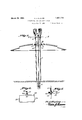
'" In describing my invention in detail, reference will be had to the accompanying drawings wherein like characters denote like or corresponding parts throughout the several views, and in which Figure l is a View in elevation of a combined bow and arrow stand embodying the invention.
Figure 2 is a horizontal sectional view on the line 22 of Figure 1 looking in the direction indicated by the arrows.
Figure 3 is a detail vertical sectional View through the standard of the device, the arrow supporting means being housed therein.
Figure 4 is a detail view in elevation, illustrating one form of how support embodying the invention, the bow supporting unit being shown in full lines in position for use and in dotted lines in .folded position.
Figure 5 is a vertical sectional View on the line 55 of Figure 4 looking in the direction indicated by the arrows.
Figure 6 is a plan view illustrating a modified form of bow holder.
Figure 7 is a view in side elevation of the holder shown in Figure 6.
The stand embodying the invention comprises a standard which is indicated by the numeral 1, and which is preferably of hollow formation except at its lower end which is pointed or tapered as at 2- to adapt the same to be readily inserted or driven into the ground a sufficient distance to support the standard in upright position. For a purpose to be presently explained, the standard is formed, in its upper end, with diametrically oppositely located slots 3, and a cap member which is indicated by the numeral 4, is fitted over this end of the standard and is likewise formed with diametrically oppositely located slots indicated by the numeral 5.
One portion of the device is intended for the support of arrows, and the other for the supportof a bow and, referring firstto the arrow support, the same comprises a leaf spring which is indicated by the numeral 6, and which is provided at one end with a knurled finger knob? which is of a diameter to adapt it to fit within the cap 4. In utilizing the arrow holder, the spring 5 is bowed to substantially annular form as shown in Figure 2 and with its end portions overlapped in the manner shown in this figure, the cap member 4 having been removed from the standard 1, and the overlapped portions of the spring are therefore readily insertible in the slots 3. The cap t is then fitted to the upper end of the standard and, if necessary,
rotated so as to bring its slots 5 into registrasupporting the arrows: in" upright position) with their pointed ends or tips disposed upon the ground and their upper portions engagedwithin the bounds of the spring.
The standard 1 is, as before stated, of'liollow form: and-the spring 6 will beformedof awidth slightly less than the interior diameter ofthe: standard, so that the spring, when separatedlfrom-the standard, may he slid into the standard, and the capmember d then ap-- plied to-the-upper end of the standard so as to close this end and likewise anchor thefinger piece?- of the said spring 'llhe bow holder, inthe embodiment shown in Figures 1, 2, d and f the-drawingswom prises a collar 8 which is preferably ofrectangular form and: provided with a bore; 9 whereby it may berslidablyi fitted upon the, standard. 1, a set screw 1(1- being, threaded through the rear side ofthe collar and adjustable to bind against the standard to hold the collarin its positions ofvertical adjustment. An arm 11 is fitted to theflat side of the collar 8v which is opposite the: side at whichthe set screw 10 is located, and a pin 12 is fitted through the; inner end. of this arm, and into the collar and a rivet 13 is secured through an opening; formed centrally in an can 14 formed integral with the. said inner endof the arm. 11, and this rivet: extends through the inner end of another arm which. is indicated by the numeral 15., and. which is recessed as at 16, at its inner end,,toaccommo-- date the ear 1 1,. the arm 15 being adapted 1' tohe swung. about the pivot 13 to assume the folded position shown in dotted lines: in Figure 4 ofthe drawings. The arms 11 and" 1 5 areprovided att-hei-r outer ends with right angularly forwardly extending supporting portions indicated respectivel-y'by the numerale-17 and 18, and, each of these portions has its uaper edge of arcuate form, or in. other wor s, curveddownwardly from end to end, as indicated by the numeral 19, so that the bow may be disposed to rest upon these members- 17 and 18in the concave upper sides thereof with its: string extending beneath the said members 1.7 and 18, the said how being indicated by the reference letter B and, as
" illustrated in Figure 2, the bow supporting unit is located at that side of the upright 1 opposite the side at which the arrow supporting unit is located, so that there will be no interference with either unit on the part of the other.
Figures 6 and 7 of the drawings illustrate a modification of the invention, and in this embodiment a preferably rectangular or cubical collar 20, corresponding to the collar 8 of the previously described form, is fitted to the up right or standard which is indicated by the numeral 21, and held in place by a set screw 22 corresponding to the set screw 10, a rectangular frame of relatively heavy resilient wire, indicated by the numeral 23 has its end members 24bent tolcurved form so as to properly seat the bow and in the same manner as theconcaveupperedges 19 of the supporting members 17 and 18 of the previously described embodiment, the front member of the frame 23 isintegral, but the rear member is divided between its ends and has its extremities turned rearwardly at rightangles as indicated-by the 1ll-ll111'dl'.25,fl1ld weldedror otherwise secured to the collar 20, or these extremities may be fitted in sockets in the said collar so as to enable the frame and collar to be separated from eachother.
What I claim is a 1.. An; arrow stand. comprising a standard havinga diametrical slot in, its upper end, a cap member removably fitted to the said end of the standard and. also provided with a diamctric, slot, and an arrow supporting member comprising a leaf springto be bowed and; fitted, at. its overlapped ends in the slots inthe standard and cap membcn.
2. An arrow stand comprising a standard having a diametric slot. in its upper, end, a
capmember removably fitted to the said end of the standard and also provided with a diametric slot, and; an arrow supportingmember comprising a leaf spring to be bowed and fitted atits overlapped ends in the slots: in
the-standardand cap member, the said standard being hollow and open at, its upper end and closed and pointed atits lower end, and the said, spring being of a width less than the diameter of. the bore of the standard, whereby the spring may be stored within, the standard, when not in use.
3. An arrow stand comprising a standard having a diametric slot in its upper end, a cap member removably fitted to the said end of the standard and also provided. with a diametric slot, and an arrow supporting member comprising a leaf spring to be bowed and fitted at its overlapping ends in the slots in the standard and cap member, the said spring being provided at one end with a head.
4.. A bow support comprising a standard, a collar adjustably mounted upon the standard, means for holding the collar in its positions of adjustment, an arm extending from the collar at one side thereof, an arm extending from the collar at the other side thereof, the first mentioned arm being fixed with respect to the collar, means pivotally connecting the second mentioned arm with the collar whereby to provide for folding of the second mentioned arm to position overlying the first mentioned arm, and extensions at the outer ends of the arms having concave upright sides for seating a bow disposed thereon.
5. A combined arrow and bow stand comprising a standard, an annular arrow support mounted upon the standard at the upper end thereof for supporting the arrows in an upright position, said annular arrow support extending horizontally through the standard at one side thereof, a member frictionally engaging the upper end of said standard for retaining the arrow support thereon, and a bow supporting member at the other side of the standard having a concaved bow supporting portion to seat a bow disposed thereon and support the same in horizontal position.
In testimony whereof I afiix my signature.
HAROLD J. SLATER.
Priority Applications (1)
| Application Number | Priority Date | Filing Date | Title |
|---|---|---|---|
| US426160A US1851779A (en) | 1930-02-05 | 1930-02-05 | Collapsible bow and arrow stand |
Applications Claiming Priority (1)
| Application Number | Priority Date | Filing Date | Title |
|---|---|---|---|
| US426160A US1851779A (en) | 1930-02-05 | 1930-02-05 | Collapsible bow and arrow stand |
Publications (1)
| Publication Number | Publication Date |
|---|---|
| US1851779A true US1851779A (en) | 1932-03-29 |
Family
ID=23689588
Family Applications (1)
| Application Number | Title | Priority Date | Filing Date |
|---|---|---|---|
| US426160A Expired - Lifetime US1851779A (en) | 1930-02-05 | 1930-02-05 | Collapsible bow and arrow stand |
Country Status (1)
| Country | Link |
|---|---|
| US (1) | US1851779A (en) |
Cited By (12)
| Publication number | Priority date | Publication date | Assignee | Title |
|---|---|---|---|---|
| US2593789A (en) * | 1946-03-25 | 1952-04-22 | Ben Pearson Inc | Support for archery equipment |
| US3584820A (en) * | 1969-01-31 | 1971-06-15 | John A Butcher Sr | Archery bow stand |
| US3991780A (en) * | 1976-02-10 | 1976-11-16 | Maroski Jr Frank M | Combination archery bow stand, walking cane and animal dragging device |
| DE2738460A1 (en) * | 1977-08-26 | 1979-03-01 | Robin Sport | Archery stand for safe storage of bow - has vertical column with clamping bracket for depositing tensioned bow facing upwardly |
| US4377270A (en) * | 1980-07-24 | 1983-03-22 | Kolongowski Sidney C | Bow holder |
| US4993398A (en) * | 1989-10-27 | 1991-02-19 | Wallace James R | Archery bow support stand |
| US5619981A (en) * | 1996-02-05 | 1997-04-15 | Breedlove; Charles E. | Archery bow stabilizer and prop |
| US6205992B1 (en) | 1999-12-04 | 2001-03-27 | Randy Meeks | Adjustable stand for an archery bow |
| US7156086B1 (en) | 2005-05-09 | 2007-01-02 | Wells Carl B | Bow holding stand assembly |
| US7484699B1 (en) | 2005-07-19 | 2009-02-03 | Rick Lee Ziegler | Support for hunting implements and accessories |
| US20100258516A1 (en) * | 2009-04-09 | 2010-10-14 | Jarvis Dewayne Howard | Lazy man's stand |
| US20110024374A1 (en) * | 2009-07-28 | 2011-02-03 | Stanley Neil Brown | Collapsible bow and arrow stand |
-
1930
- 1930-02-05 US US426160A patent/US1851779A/en not_active Expired - Lifetime
Cited By (13)
| Publication number | Priority date | Publication date | Assignee | Title |
|---|---|---|---|---|
| US2593789A (en) * | 1946-03-25 | 1952-04-22 | Ben Pearson Inc | Support for archery equipment |
| US3584820A (en) * | 1969-01-31 | 1971-06-15 | John A Butcher Sr | Archery bow stand |
| US3991780A (en) * | 1976-02-10 | 1976-11-16 | Maroski Jr Frank M | Combination archery bow stand, walking cane and animal dragging device |
| DE2738460A1 (en) * | 1977-08-26 | 1979-03-01 | Robin Sport | Archery stand for safe storage of bow - has vertical column with clamping bracket for depositing tensioned bow facing upwardly |
| US4377270A (en) * | 1980-07-24 | 1983-03-22 | Kolongowski Sidney C | Bow holder |
| US4993398A (en) * | 1989-10-27 | 1991-02-19 | Wallace James R | Archery bow support stand |
| US5619981A (en) * | 1996-02-05 | 1997-04-15 | Breedlove; Charles E. | Archery bow stabilizer and prop |
| US6205992B1 (en) | 1999-12-04 | 2001-03-27 | Randy Meeks | Adjustable stand for an archery bow |
| US7156086B1 (en) | 2005-05-09 | 2007-01-02 | Wells Carl B | Bow holding stand assembly |
| US7484699B1 (en) | 2005-07-19 | 2009-02-03 | Rick Lee Ziegler | Support for hunting implements and accessories |
| US20100258516A1 (en) * | 2009-04-09 | 2010-10-14 | Jarvis Dewayne Howard | Lazy man's stand |
| US20110024374A1 (en) * | 2009-07-28 | 2011-02-03 | Stanley Neil Brown | Collapsible bow and arrow stand |
| US8162157B2 (en) * | 2009-07-28 | 2012-04-24 | Bowsaver Inc | Collapsible bow and arrow stand |
Similar Documents
| Publication | Publication Date | Title |
|---|---|---|
| US1851779A (en) | Collapsible bow and arrow stand | |
| US2289701A (en) | Bottle holder | |
| US1342626A (en) | Belt-rack for supporting articles | |
| US2783572A (en) | Goose decoy | |
| US1884968A (en) | Combined flash light and reading glass | |
| US2062553A (en) | Book holder | |
| US2813294A (en) | Door holder | |
| US1761245A (en) | Multiple xylophone finger | |
| US1611835A (en) | Folding pencil compass | |
| US2573622A (en) | Garment hanger of the folding type | |
| US2013575A (en) | Watch holder | |
| US2720718A (en) | Map and blueprint holder | |
| US1740814A (en) | Bookrest | |
| US979626A (en) | Music-stand. | |
| US1866107A (en) | Attachment for holding cigarette cases | |
| US1573218A (en) | Lamp holder | |
| US1810109A (en) | Combined pencil and clip | |
| US1996234A (en) | Playing card holder | |
| US2442294A (en) | Collar attachment | |
| US1713380A (en) | Pen and pencil holder | |
| US2546589A (en) | Cord holder | |
| US2714036A (en) | Rain shield attachment for vehicle sun visors | |
| US2043019A (en) | Umbrella mirror | |
| US1289666A (en) | Cigar and cigarette holder. | |
| US2586443A (en) | Combined postal scale, check protector, and letter opener |