US1851756A - Casting machine - Google Patents
Casting machine Download PDFInfo
- Publication number
- US1851756A US1851756A US465500A US46550030A US1851756A US 1851756 A US1851756 A US 1851756A US 465500 A US465500 A US 465500A US 46550030 A US46550030 A US 46550030A US 1851756 A US1851756 A US 1851756A
- Authority
- US
- United States
- Prior art keywords
- gooseneck
- nozzle
- metal
- intake
- air
- Prior art date
- Legal status (The legal status is an assumption and is not a legal conclusion. Google has not performed a legal analysis and makes no representation as to the accuracy of the status listed.)
- Expired - Lifetime
Links
- 238000005266 casting Methods 0.000 title description 11
- 244000261422 Lysimachia clethroides Species 0.000 description 48
- 239000002184 metal Substances 0.000 description 26
- 230000008018 melting Effects 0.000 description 4
- 238000002844 melting Methods 0.000 description 4
- 238000010276 construction Methods 0.000 description 3
- 238000004512 die casting Methods 0.000 description 2
- 230000000994 depressogenic effect Effects 0.000 description 1
- 238000007598 dipping method Methods 0.000 description 1
- 238000007599 discharging Methods 0.000 description 1
Images

Classifications
-
- B—PERFORMING OPERATIONS; TRANSPORTING
- B22—CASTING; POWDER METALLURGY
- B22D—CASTING OF METALS; CASTING OF OTHER SUBSTANCES BY THE SAME PROCESSES OR DEVICES
- B22D17/00—Pressure die casting or injection die casting, i.e. casting in which the metal is forced into a mould under high pressure
- B22D17/02—Hot chamber machines, i.e. with heated press chamber in which metal is melted
- B22D17/06—Air injection machines
Definitions
- This invention relates to casting machines. It is particularly applicable to die casting machines of the type in which the molten metal is dipped out of the melting pot by a movable dipping member or gooseneck and discharged into a horizontally operated mold by air pressure.
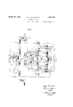
- Figure II is a plan view of the apparatus with the gooseneck in position for injecting the metal into the mold.
- 1 is a plate in which is mounted the gate bushing 2 in which is formed the gate 3.
- the gooseneck is provided with hooked lugs 6 and 7, the former of which issupported' by a rod 8 which has rollers 9 at each end thereof.
- These rollers run on brackets 10, mounted on the plate 1 or in any other suitable manner, forming tracks 11, the outer portions of which extend over the melting pot, being downwardly inclined, while the portions of the tracks nearest to the plate 1 are preferably substantially 15 pre erably in the form of a horizontal. Any suitable configuration may be given to the tracks to secure the desired path of movement of the rollers 9 and rod 8.
- the In s 7 on the gooseneck engage a crank ent rod, the shaft portions 16 of which are mounted in bearing blocks 17. Movement is imparted to the gooseneck by means of a pair of toggle links 20, which engage the shaft 8 at one end, while the other ends of the links are pivmeans of the screw 32.
- the shaft 23 is mounted on the bracket 30 which is preferably adjustably mounted on the base plate 31, and may be held in desired adjustment by The permissible range of movement of the crank arm 22 may be adjusted by means of adjusting screws 33 and. 34, carried by the bracket 30.
- the screw 33 is engaged by a lug 35 projecting from the rear end of the crank arm 22 when the parts are in the vposition shown in the full lines in Fig. I, while thevscrew 34 is engaged by the crank arm 22 when the parts are retracted into the dotted line position.
- a pipe 40 isv provided to carry compressed air to the gooseneck, this pipe having a movable section 41 swivelle'd to it at 42, the movable section'being connected to a hollow block or fitting 43, provided with trunnions 44 which are pivoted in links 45, the rear ends of which are pivoted upon the pin 21.
- the fitting 43 is provided with an air outlet bushing 46, preferably having a tapered or otherwise suitably formed mouth 47.
- the gooseneck 5 is preferably provided with a discharge nozzle 50 which may be of usual form and preferably tapered to engage the gate bushing arid which is usually-made of hard and heat resisting metal.
- he gooseneck is also provided with an intake nozzle 51 which is preferably tapered for engagement with the air discharge bushing 46 and which is also preferably provided with an extension portion 52 extending within the gooseneck, and curving into the upper portion thereof.
- the point of discharge of the air into the gooseneck in this machine is preferably above the level of the metal in the gooseneck, this being accomplished in the construction shown by providing the upwardly curved extension 52.
- the advantage of this is that if there is any leak between the bushing 46 and the intake nozzle 51, air only will leak out of this point which will cause no damage, 'whereas if the air were discharged below the level of the metal, it would force metal out through any leak with to the apparatus and danger to the operator.
- a. gooseneck having a discharge nozzle and an intake port, the molten metal being introduced into said gooseneck throu b said intake port, and means for intro ucingrompressedair into said gooseneck through said intake port.
- a gooseneck having a discharge nozzle and an intake port, the molten metal being introduced into said gooseneck through said intake port, and means for introducing compressed air into saidgooseneck through said intake port, said means discharging the air into the gooseneck above the level of the metal therein.
- a movable air connection means for moving and holding said air connection against said intake nozzle, and means for moving and holding said discharge nozzle against the gate bushing.
- a movable gooseneck having a discharge nozzle at the front and intake port at the rear, and means for supporting said gooseneck and guiding said discharge nozzle into and away from its discharge position, said means including a track, means connected with the gooseneck running over said track, and means cooperating with the track to cause the gooseneck in moving away from discharge position to travel at first directly awayand then to tilt the rear end down to submerge the intake port while maintaining the discharge nozzle unsubmerged.
- a movable gooseneck having a ischarge nozzle and having an intake port in the rear part thereof, means for movably supporting said gooseneck so as to permit movement of the same from a position in which the rear end thereof is depressed into a position in which the discharge nozm zle thereof is engaged with the gate bushing, and tog le links for moving said gooseneck and hol ing'said discharge nozzle in engagement with the gate bushing.
- a gooseneck for casting machines having a discharge nozzle at one end thereof and an intake nozzle for the molten metal at the other end thereof in substantially direct- I ly opposed relation to one another, each of said nozzles having a projecting tapered pertion.
- a gooseneck for casting machines having a discharge nozzle at one end thereof and an intake nozzle for'the molten metal at the other end thereof, means for in'ecting air through the intake nozzle, said int e nozzle having an upwardly directed duct inside of the gooseneck through which the air and metal must pass. 7 p
- a gooseneck for casting machines having a nozzle for the reception of metal and the introduction of compressed air into the gooseneck below the top thereof, said nozzle (provided with an extension portion exten ing through the gooseneck to a point near the top thereof. 0
- a gooseneck havin a substantially horizontally disposed dischar e nozzle at the front thereof, a substantial y n horizontally disposed intake nozzle at the rear thereof, means for retractin the gooseneck to a withdrawn downwar ly inclined position for submer ing the intake nozzle in molten metal, and for restoring it to a substantially horizontal casting position, an air duct movable into sealed connection with the intake nozzle, and means for movin said duct against said nozzle in a direction to press t e gooseneck toward the mold.
- 5o 10 A structure as set forth in claim 9, in
- the gooseneck operating means comrises a handle, a short link in fixed relation t ereto, and a relatively long link pivotally connected to the short link, and in which the air duct operating means comprises the same handle, the same short link, and a second relatively short link pivoted to the first mentioned short link.
Landscapes
- Engineering & Computer Science (AREA)
- Mechanical Engineering (AREA)
- Casting Support Devices, Ladles, And Melt Control Thereby (AREA)
Description
March 29, 1932.
E. N. DOLLlN ET AL CASTING MACHINE Filed July 3. 1930 2 Sheets-Sheet Mb I, r i-5%..
w I NVEP; OR
ATTORNEY PatentedMar. 29; 1332 v UNITED STATES PATENT OFFICE EDGAR N. DOLLIN, OF HALBA, AND WILLIAM ASSIGNOBS .10 ALLIED DIE-CASTING CO YORK, A CORPORATION NEW YORK 'GEBAUEB, or mansrnILLs, new Yonx,
BPOBATION, OF LONG ISLAND CITY, NEW
This invention relates to casting machines. It is particularly applicable to die casting machines of the type in which the molten metal is dipped out of the melting pot by a movable dipping member or gooseneck and discharged into a horizontally operated mold by air pressure. I
An object of the invention is to provide a machine of this character which is simple in -construction, durable and capable of rapid hand or automatic operation. More s ecific objects and advantages will appear in the course of the detailed description of one preferred embodiment of the invention. In the drawings which illustrate such preferred embodiment! Figure I is a vertical section of the machine showing in full lines the parts in position for injecting the metal into the mold,
and in dotted lines the'position in which the gooseneck is being refilled with metal; and
Figure II isa plan view of the apparatus with the gooseneck in position for injecting the metal into the mold.
Referring to the drawings in detail, 1 is a plate in which is mounted the gate bushing 2 in which is formed the gate 3. A mold, not shown, is held in contact with the outer face of plate 1 in a well understood manner. 4
is a melting pot for the metal and 5 is the movable gooseneck. The gooseneck is provided with hooked lugs 6 and 7, the former of which issupported' by a rod 8 which has rollers 9 at each end thereof. These rollers run on brackets 10, mounted on the plate 1 or in any other suitable manner, forming tracks 11, the outer portions of which extend over the melting pot, being downwardly inclined, while the portions of the tracks nearest to the plate 1 are preferably substantially 15 pre erably in the form of a horizontal. Any suitable configuration may be given to the tracks to secure the desired path of movement of the rollers 9 and rod 8. The In s 7 on the gooseneck engage a crank ent rod, the shaft portions 16 of which are mounted in bearing blocks 17. Movement is imparted to the gooseneck by means of a pair of toggle links 20, which engage the shaft 8 at one end, while the other ends of the links are pivmeans of the screw 32.
oted upon the pin 21, carried by a crank arm erating the same, and preferably with a counterweight 25 mounted on arm 26. The shaft 23 is mounted on the bracket 30 which is preferably adjustably mounted on the base plate 31, and may be held in desired adjustment by The permissible range of movement of the crank arm 22 may be adjusted by means of adjusting screws 33 and. 34, carried by the bracket 30. The screw 33 is engaged by a lug 35 projecting from the rear end of the crank arm 22 when the parts are in the vposition shown in the full lines in Fig. I, while thevscrew 34 is engaged by the crank arm 22 when the parts are retracted into the dotted line position. A pipe 40 isv provided to carry compressed air to the gooseneck, this pipe having a movable section 41 swivelle'd to it at 42, the movable section'being connected to a hollow block or fitting 43, provided with trunnions 44 which are pivoted in links 45, the rear ends of which are pivoted upon the pin 21. The fitting 43 is provided with an air outlet bushing 46, preferably having a tapered or otherwise suitably formed mouth 47. The gooseneck 5 is preferably provided with a discharge nozzle 50 which may be of usual form and preferably tapered to engage the gate bushing arid which is usually-made of hard and heat resisting metal. he gooseneckis also provided with an intake nozzle 51 which is preferably tapered for engagement with the air discharge bushing 46 and which is also preferably provided with an extension portion 52 extending within the gooseneck, and curving into the upper portion thereof.
In operation the pot 4 is filled with molten metal to the approximate level marked 60. The parts are retracted to the dotted line position shown in Fig. I in which position it will be seen that the gooseneck is partly submerged in the molten metal, the upper end of the intake nozzle extension 52 being below the level of the metal in the pot. The metal will now run into the gooseneck through the intake port 51, the air in the gooseneck escaping through discharge nozzle the rear end of the goosenec the top of the 50. Hand lever 24 is now operated to brfinfi the parts to the position shown in the lines in Fig. I during which operation the rollers 9 roll up the inclined portions of the tracks 11 and on to the horizontal portions thereof, thus guiding the discharge nozzle into proper contact with the ate bushing 2, at the same time being raised from the melting pot by the upward swing of the crank 15. .The pin 21 passes the dead center between the pins 23 and 8 before the lug 35 engages the end of screw 33 so that the crank arm 22 and links 20 form a toggle firmly locking) the nozzle 50 in engagement with the gate ushing 2. Movement of the crank arm 22 also acts through the links 45 to swing the pipe 41 so as to bring the bushing 46 into engagement with the intake nozzle 51, the crankarm 22 also constituting a toggle in connection with the links 45 so as to lock the-bushing 46 firmly in contact with the intake nozzle. The air pressure is now turned on, entering ooseneck through the curved extension 52 a ove the level of the metal therein, and forcing the metal rapidly out of.
the gooseneck through the gate 3 into the mold in a well understood manner.
The point of discharge of the air into the gooseneck in this machine is preferably above the level of the metal in the gooseneck, this being accomplished in the construction shown by providing the upwardly curved extension 52. The advantage of this is that if there is any leak between the bushing 46 and the intake nozzle 51, air only will leak out of this point which will cause no damage, 'whereas if the air were discharged below the level of the metal, it would force metal out through any leak with to the apparatus and danger to the operator.
Intake nozzle 51 is also preferably made larger in diameter than the discharge nozzle 50, so that the force produced by the air pressure within the gooseneck tending to separate nozzle 51 from bush1ng46 is greater than the corresponding force tending to separate nozzle 50 from the gate bushing 2. As a result of this differential, the air pressure tends to hold the discharge nozzle 50 tightly against the bushing 2, and if there is any leakage at either of the nozzles, it will be at the larger intake nozzle where air only will escape, as
before explained, and not at the discharge nozzle where metal would be ejected. The
larger intake nozzle also permits a quicker filling of the gooseneck when submerged in the molten metal than would be the case if the gooseneck were 'filled through the discharge nozzle, as has heretofore been customary in machines having movable goosenecks, the permissible size of the discharge nozzle being limited by the size of the gate which itis practicable to use.
1 Another advantage of the separate intake consequent damage I ter submergence of the gooseneck in the meltpot thereby permitting more metal to ing be ta en from the pot into the gooseneck than has been the case with machines heretofore commonly employed, in which the dischargenozzle of the gooseneck was submerged in the pot.
While we have illustrated and described in detail certain preferred forms of our invention,.it is to be understood that changes may be made therein and the invention embodied in other structures. We do not, therefore, desire to limit ourselves to the specific constructions illustrated, but intend to coverour invention broadly in whatever form its principle may be utilized.
We claim:
1. In a casting machine, a. gooseneck having a discharge nozzle and an intake port, the molten metal being introduced into said gooseneck throu b said intake port, and means for intro ucingrompressedair into said gooseneck through said intake port.
2. In a casting machine, a gooseneck having a discharge nozzle and an intake port, the molten metal being introduced into said gooseneck through said intake port, and means for introducing compressed air into saidgooseneck through said intake port, said means discharging the air into the gooseneck above the level of the metal therein.
3. In a casting machine, a movable gooseneck having a discharge nozzle and an intakenozzle extending substantially in opposite directions from the front and back of the gooseneck, respectively, adapted to be applied to said intake nozzle,
a movable air connection means for moving and holding said air connection against said intake nozzle, and means for moving and holding said discharge nozzle against the gate bushing.
4. In a casting machine, a movable gooseneck having a discharge nozzle at the front and intake port at the rear, and means for supporting said gooseneck and guiding said discharge nozzle into and away from its discharge position, said means including a track, means connected with the gooseneck running over said track, and means cooperating with the track to cause the gooseneck in moving away from discharge position to travel at first directly awayand then to tilt the rear end down to submerge the intake port while maintaining the discharge nozzle unsubmerged.
5. In a castin machine, a movable gooseneck having a ischarge nozzle and having an intake port in the rear part thereof, means for movably supporting said gooseneck so as to permit movement of the same from a position in which the rear end thereof is depressed into a position in which the discharge nozm zle thereof is engaged with the gate bushing, and tog le links for moving said gooseneck and hol ing'said discharge nozzle in engagement with the gate bushing. 6. A gooseneck for casting machines having a discharge nozzle at one end thereof and an intake nozzle for the molten metal at the other end thereof in substantially direct- I ly opposed relation to one another, each of said nozzles having a projecting tapered pertion.
7. A gooseneck for casting machines having a discharge nozzle at one end thereof and an intake nozzle for'the molten metal at the other end thereof, means for in'ecting air through the intake nozzle, said int e nozzle having an upwardly directed duct inside of the gooseneck through which the air and metal must pass. 7 p
8. A gooseneck for casting machines having a nozzle for the reception of metal and the introduction of compressed air into the gooseneck below the top thereof, said nozzle (provided with an extension portion exten ing through the gooseneck to a point near the top thereof. 0
9. In a castin machine, the combination with a mold, o a gooseneck havin a substantially horizontally disposed dischar e nozzle at the front thereof, a substantial y n horizontally disposed intake nozzle at the rear thereof, means for retractin the gooseneck to a withdrawn downwar ly inclined position for submer ing the intake nozzle in molten metal, and for restoring it to a substantially horizontal casting position, an air duct movable into sealed connection with the intake nozzle, and means for movin said duct against said nozzle in a direction to press t e gooseneck toward the mold. 5o 10. A structure as set forth in claim 9, in
which the gooseneck operating means comrises a handle, a short link in fixed relation t ereto, and a relatively long link pivotally connected to the short link, and in which the air duct operating means comprises the same handle, the same short link, and a second relatively short link pivoted to the first mentioned short link.
In testimony whereof we have aflixed our 5 signatures to this specification.
EDGAR N. DOLLIN. WILLIAM GEBA'UER.
Priority Applications (1)
| Application Number | Priority Date | Filing Date | Title |
|---|---|---|---|
| US465500A US1851756A (en) | 1930-07-03 | 1930-07-03 | Casting machine |
Applications Claiming Priority (1)
| Application Number | Priority Date | Filing Date | Title |
|---|---|---|---|
| US465500A US1851756A (en) | 1930-07-03 | 1930-07-03 | Casting machine |
Publications (1)
| Publication Number | Publication Date |
|---|---|
| US1851756A true US1851756A (en) | 1932-03-29 |
Family
ID=23848068
Family Applications (1)
| Application Number | Title | Priority Date | Filing Date |
|---|---|---|---|
| US465500A Expired - Lifetime US1851756A (en) | 1930-07-03 | 1930-07-03 | Casting machine |
Country Status (1)
| Country | Link |
|---|---|
| US (1) | US1851756A (en) |
-
1930
- 1930-07-03 US US465500A patent/US1851756A/en not_active Expired - Lifetime
Similar Documents
| Publication | Publication Date | Title |
|---|---|---|
| US2262615A (en) | Casting machine | |
| CN115283619A (en) | Alloy casting equipment and casting method thereof | |
| US1851756A (en) | Casting machine | |
| US2892225A (en) | Process and means for casting system for operating pouring ladles | |
| US2131955A (en) | Die casting machine | |
| US2082588A (en) | Apparatus for producing slush castings | |
| US2853755A (en) | Centrifugal casting method | |
| US3397735A (en) | Pull and spray station for centrifugal casting machine | |
| US2893081A (en) | Ingot casting machine | |
| US2000488A (en) | Die casting machine | |
| US2265740A (en) | Method and apparatus for supplying fluxing material | |
| US2224978A (en) | Melting pot for casting machines | |
| US1354732A (en) | Casting-machine | |
| US1620829A (en) | Method of and apparatus for centrifugally casting metal bodies | |
| US3334683A (en) | Trough shifting and dumping apparatus | |
| US3181212A (en) | Die casting machine | |
| US2676370A (en) | Die casting machine with automatic ladle | |
| US2308395A (en) | Production of castings | |
| KR100370891B1 (en) | Mando machinery corporation | |
| US1720357A (en) | Automatic casting machine | |
| US1956002A (en) | Die casting machine | |
| US1908032A (en) | Gooseneck operating means for die casting pumps | |
| US1442479A (en) | Die-casting apparatus | |
| US1620831A (en) | Charging device for tilting molds | |
| US2763042A (en) | Apparatus for applying lining to bearings |