US185173A - Improvement in dies for making watch-case bezels - Google Patents
Improvement in dies for making watch-case bezels Download PDFInfo
- Publication number
- US185173A US185173A US185173DA US185173A US 185173 A US185173 A US 185173A US 185173D A US185173D A US 185173DA US 185173 A US185173 A US 185173A
- Authority
- US
- United States
- Prior art keywords
- dies
- bezels
- case
- improvement
- making watch
- Prior art date
- Legal status (The legal status is an assumption and is not a legal conclusion. Google has not performed a legal analysis and makes no representation as to the accuracy of the status listed.)
- Expired - Lifetime
Links
- 239000002184 metal Substances 0.000 description 2
- 229910001369 Brass Inorganic materials 0.000 description 1
- 239000010951 brass Substances 0.000 description 1
- 238000004519 manufacturing process Methods 0.000 description 1
- 229910000679 solder Inorganic materials 0.000 description 1
Images
Classifications
-
- B—PERFORMING OPERATIONS; TRANSPORTING
- B21—MECHANICAL METAL-WORKING WITHOUT ESSENTIALLY REMOVING MATERIAL; PUNCHING METAL
- B21D—WORKING OR PROCESSING OF SHEET METAL OR METAL TUBES, RODS OR PROFILES WITHOUT ESSENTIALLY REMOVING MATERIAL; PUNCHING METAL
- B21D28/00—Shaping by press-cutting; Perforating
- B21D28/02—Punching blanks or articles with or without obtaining scrap; Notching
- B21D28/06—Making more than one part out of the same blank; Scrapless working
Definitions
- Watch-cases have heretofore been made in the following manner: The metal was firs-t Bezels and centers were then drawn from the bars by a draw-bench through a draw plate or dies, then cut oft' in suitable lengths, soldered, and swaged down to a suitable shape and size. For the backs and caps plates were rolled out through rollers to the required thickness, out in shape with shears, and swaged up by followers, made usually of brass or composition. Snaps were then soldered on and the pieces finished up in lathes, and the required form given to them by means of gravers and different other and well-known tools.
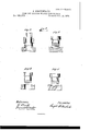
- a round blank, Fig. l is cut from a sheet of metal, and the shape given to it, as seen in Fig. 2, by means of dies, as shown in Fig. 3.
- the piece is then placed in dies shown in Fig. 4, and the shape given to it at the margin, as seen in Fig. 5, and by a second operation with the last referred to lower die, and an upper die, such as shown in Fig. 6, not quite so deep as the former upper die, the outer rim is crowded down s0 as to increase the thickness ot' the bezel at the point where the snap is formed, as seen in Fig. 7.
- the piece is then put into dies shown in Fig. 8, and a round plate is out out ot' it, thus leaving the interior ot' the bezel suitable for working on in the linishing of it up, as shown in Figs. 9 or 10.
Landscapes
- Engineering & Computer Science (AREA)
- Mechanical Engineering (AREA)
- Shaping Metal By Deep-Drawing, Or The Like (AREA)
Description
ZSheets-Sheet 1. J. FC)RlENIBAGH.
DIES FOR MAKING WATCH-CASE BEZYELS. No.185,173. Pateted Dec.12,18x76.
THE GRAPHIC COJLL l y 2 Sheets--Sheet 2. J. FORTENBACH.
DIES FOR MAKING WATCH-CASE BEZELS. Ng, 1851173, Patented Dec.12, 1876.
cast into bars.
ETE
eren.
IIIIIPROVlEIVIEN'I' IN DIES FOR MAKING WATCH-CASE BEZELS.
Specification forming part of Letters Patent No. l @5,173, dated December 12, 1876; application tiled May 7, 1875.
To all whom it may concern:
Be it known that I, J osnrn FORTENBACH,
otCarlstadt, Bergen county, in the State of New Jersey, have invented certain new and useful Improvements in the Manufacture of Bezels for VatchCases, of which the following is a full, clear, and exact description, reterence being. `nad to the drawings, forming a part of this specification.
Watch-cases have heretofore been made in the following manner: The metal was firs-t Bezels and centers were then drawn from the bars by a draw-bench through a draw plate or dies, then cut oft' in suitable lengths, soldered, and swaged down to a suitable shape and size. For the backs and caps plates were rolled out through rollers to the required thickness, out in shape with shears, and swaged up by followers, made usually of brass or composition. Snaps were then soldered on and the pieces finished up in lathes, and the required form given to them by means of gravers and different other and well-known tools.
l'the centers containing shoulders for bezels and caps, back and front backs, the bezels to their proper shape, and the covers containing snaps formed solidly thereto, thereby avoiding the necessity of solder and much manual labor in the attachment of such snaps.
To make bezels, which is the subject-matter of the present application, a round blank, Fig. l, is cut from a sheet of metal, and the shape given to it, as seen in Fig. 2, by means of dies, as shown in Fig. 3. The piece is then placed in dies shown in Fig. 4, and the shape given to it at the margin, as seen in Fig. 5, and by a second operation with the last referred to lower die, and an upper die, such as shown in Fig. 6, not quite so deep as the former upper die, the outer rim is crowded down s0 as to increase the thickness ot' the bezel at the point where the snap is formed, as seen in Fig. 7.
The piece is then put into dies shown in Fig. 8, and a round plate is out out ot' it, thus leaving the interior ot' the bezel suitable for working on in the linishing of it up, as shown in Figs. 9 or 10.
I claim- 1. The combination of 'the dies shown in Figs. 3, 4, 6, and S, substantially as and for the purpose described.
2. The dies shown in Fig. 4, substantially `as described.
Publications (1)
| Publication Number | Publication Date |
|---|---|
| US185173A true US185173A (en) | 1876-12-12 |
Family
ID=2254578
Family Applications (1)
| Application Number | Title | Priority Date | Filing Date |
|---|---|---|---|
| US185173D Expired - Lifetime US185173A (en) | Improvement in dies for making watch-case bezels |
Country Status (1)
| Country | Link |
|---|---|
| US (1) | US185173A (en) |
-
0
- US US185173D patent/US185173A/en not_active Expired - Lifetime
Similar Documents
| Publication | Publication Date | Title |
|---|---|---|
| CN103372605A (en) | Multi-procedure punching compound die | |
| CN206622522U (en) | A kind of convertible short tube mould | |
| CN106914507A (en) | A kind of large gear local induction heating extrusion forming method | |
| CN203091525U (en) | Multi-process stamping compound die | |
| US185173A (en) | Improvement in dies for making watch-case bezels | |
| CN100333852C (en) | Precise punch technology for manufacturing circular or sectorial gear | |
| US1640964A (en) | Roll-making machine | |
| US1499309A (en) | Punching tool and method of making same | |
| US1821457A (en) | Metal flanging or cutting and flanging machine | |
| CN103691839A (en) | Forming method for parts like automobile beams | |
| US501900A (en) | Method of and apparatus for the manufacture of hollow articles | |
| CN102699641A (en) | Method for processing bush of curve step | |
| US1331921A (en) | Base-plug for time-fuses | |
| US185174A (en) | Improvement in dies for making watch-case centers | |
| US1118180A (en) | Process of making steel die-punches. | |
| US185172A (en) | Improvement in dies for making watch-case backs | |
| US1374223A (en) | Machine for forming metal blanks | |
| US2120094A (en) | Apparatus for making sinks | |
| US3131472A (en) | Method of making blanks for coining | |
| US121172A (en) | Improvement in machines for making axes | |
| US56337A (en) | Improvement in the manufacture of spoons, forks | |
| US260196A (en) | Rolling-mill | |
| US627558A (en) | Drawing-die mechanism. | |
| US1747773A (en) | Type-matrix-forming punch | |
| US432635A (en) | Island |