US1851732A - Tappet production method - Google Patents
Tappet production method Download PDFInfo
- Publication number
- US1851732A US1851732A US466113A US46611330A US1851732A US 1851732 A US1851732 A US 1851732A US 466113 A US466113 A US 466113A US 46611330 A US46611330 A US 46611330A US 1851732 A US1851732 A US 1851732A
- Authority
- US
- United States
- Prior art keywords
- shank
- electrode
- heads
- tappet
- steel
- Prior art date
- Legal status (The legal status is an assumption and is not a legal conclusion. Google has not performed a legal analysis and makes no representation as to the accuracy of the status listed.)
- Expired - Lifetime
Links
- 238000004519 manufacturing process Methods 0.000 title description 10
- 229910000831 Steel Inorganic materials 0.000 description 10
- 239000010959 steel Substances 0.000 description 10
- 238000000034 method Methods 0.000 description 9
- 238000003466 welding Methods 0.000 description 7
- 229910001018 Cast iron Inorganic materials 0.000 description 4
- RYGMFSIKBFXOCR-UHFFFAOYSA-N Copper Chemical compound [Cu] RYGMFSIKBFXOCR-UHFFFAOYSA-N 0.000 description 3
- 241000277275 Oncorhynchus mykiss Species 0.000 description 3
- 229910052802 copper Inorganic materials 0.000 description 3
- 239000010949 copper Substances 0.000 description 3
- 238000005520 cutting process Methods 0.000 description 2
- 230000002349 favourable effect Effects 0.000 description 2
- 239000000463 material Substances 0.000 description 2
- 239000002184 metal Substances 0.000 description 2
- 229910052751 metal Inorganic materials 0.000 description 2
- OKTJSMMVPCPJKN-UHFFFAOYSA-N Carbon Chemical compound [C] OKTJSMMVPCPJKN-UHFFFAOYSA-N 0.000 description 1
- 230000015572 biosynthetic process Effects 0.000 description 1
- 229910052799 carbon Inorganic materials 0.000 description 1
- 238000005266 casting Methods 0.000 description 1
- 229910052729 chemical element Inorganic materials 0.000 description 1
- 238000010276 construction Methods 0.000 description 1
- 238000013461 design Methods 0.000 description 1
- 230000000694 effects Effects 0.000 description 1
- 238000005242 forging Methods 0.000 description 1
- 238000010438 heat treatment Methods 0.000 description 1
- 238000003780 insertion Methods 0.000 description 1
- 230000037431 insertion Effects 0.000 description 1
- 238000002844 melting Methods 0.000 description 1
- 230000008018 melting Effects 0.000 description 1
- 239000000203 mixture Substances 0.000 description 1
- 238000012986 modification Methods 0.000 description 1
- 230000004048 modification Effects 0.000 description 1
- 230000008520 organization Effects 0.000 description 1
- 230000000717 retained effect Effects 0.000 description 1
Images
Classifications
-
- B—PERFORMING OPERATIONS; TRANSPORTING
- B23—MACHINE TOOLS; METAL-WORKING NOT OTHERWISE PROVIDED FOR
- B23K—SOLDERING OR UNSOLDERING; WELDING; CLADDING OR PLATING BY SOLDERING OR WELDING; CUTTING BY APPLYING HEAT LOCALLY, e.g. FLAME CUTTING; WORKING BY LASER BEAM
- B23K11/00—Resistance welding; Severing by resistance heating
- B23K11/002—Resistance welding; Severing by resistance heating specially adapted for particular articles or work
-
- Y—GENERAL TAGGING OF NEW TECHNOLOGICAL DEVELOPMENTS; GENERAL TAGGING OF CROSS-SECTIONAL TECHNOLOGIES SPANNING OVER SEVERAL SECTIONS OF THE IPC; TECHNICAL SUBJECTS COVERED BY FORMER USPC CROSS-REFERENCE ART COLLECTIONS [XRACs] AND DIGESTS
- Y10—TECHNICAL SUBJECTS COVERED BY FORMER USPC
- Y10T—TECHNICAL SUBJECTS COVERED BY FORMER US CLASSIFICATION
- Y10T29/00—Metal working
- Y10T29/49—Method of mechanical manufacture
- Y10T29/49229—Prime mover or fluid pump making
- Y10T29/49298—Poppet or I.C. engine valve or valve seat making
- Y10T29/49304—Valve tappet making
Definitions
- Spot-welding methods have been found suitable to the uniting of cast tappet heads with tubular bodies formed from steel; but eflorts to unite steel heads with steel bodies of like or higher carbon content by usual 29 spot-welding methods employing external electrodes have been found unsatisfactory.
- This body of conductive metal may either be a terminal portion of a copper electrode, momentarily applied for a local heating efiect or it may be a plug of copper adapted to cooperate with an electrode or to serve as an intermediate electrode, ashereinafter described.
- the present invention has both the merit of permitting cast iron faces to be formed, as by puddling, upon steel heads not connected with bodies and also the merit of enabling any desired perfecting operations to be completed in advance of the union of the heads with tubular bodies,so that few or none of the tappets need be re jected after a final union of heads to bodies; and, although the heads employed herein may be preformed in any desired manner, it is an object of the invention to obviate all necessity for casting operations.
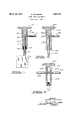
- Fig. 1 is a vertical section through an organization illustrative of the present invention but omitting structures that are immaterial to the principle thereof.
- Fig. 2 is a similar view, illustrating an alternative embodiment.
- Fig. 8 is a similar view of another alternative embodiment.
- a tubular body 10 is shown as having been preformed to include a substantially cylindrical exterior surface 11, an interiorly threaded reduced lower portion, and an upper portion providing a substantially cylindrical or slightly conical bore 13 adapted snugly to receive the shank 14 of a head 15.
- a head having the illustrated configuration may advantageously be secured to a preformed body of the illustrated type by spot-welding effected by electrodes disposed on opposite sides of the body 10 at the level of the shank 14 in case the head 15 is preformed, as herein proposed (by cutting or by forging or other similar operations) from steel similar to or less readily conductive or less readily melted than the body 10, in order to avoid transmitting an undue proportion of the welding current through the body 10 by a semicircular path or paths not including the shank 14:, the present invention contemplates the use of an external electrode 16 conjointly with an internal electrode 17 the latter being shown as inserted through the threaded opening 18 and as engaging a central concavity 19 in the lower end of the shank 14.
- the suggested facing operation, and any desired grinding or finishing operations upon a face 22a may be comp-letedinadvance of the union of the shank 1% with a body 10a,as by means of electrodes or contact elements 16a and 17 a.
- the contact element 17a is shown as inserted through a preformed 'counterbore 18a; but this showing is intended primarily to indicate that, as in theinstance first described,
- any desired steps may be performed upon either the heads 15a or the bodies 10a in advance of the uniting of the same by a welding current passed radially through the shank 14a r and the body lOain a path such as that suggested by the dotted line 20a.
- vReference characters being applied to 3'in the samegenera'l manner as to preceding figures but with a 77 added to each character, it will be noted that a so-called intermediate electrode is shown as seated in a comparatively deep concavity 19b in the shank 15b of ahead 14b, and is adopted to cooperate with 'a plurality of external electrodes 166,
- the intermediate electrode 23'?) may advantageously be formed of copper, or other highly conductivemateria-l,preferably having a drive or otherwise provided with means in connection with either orboth of the external electrodes 16?) or 16b,as also in that, whether the current flow is inward or out ward or alternating, it always follows substantially radial lines through both a shank walland a cylindrical body wall opposite the outer electrodes. Any incidental thermal expansion of the shank will be seen to favor a good conductive contact between said shank and the surrounding wall, and the prompt formation of a strong and permanent connection therebetween.
- a method which comprises: preforming an outer tubular. body from steel; separately preforming an inner ele ment having a shank to interfit with said tubular body, the lower endof said shank being formed to receivean electrode; insert ing said shank in said body; disposing elecs,
- trodes respectively in contact with said shank and said body; and passing an electric cur: rent radially through said shankand said body bymeans comprising saidelectrodes.
- a method which comprises: preforming an outer tubular body from steel; separately preforming an inner el'enientihavs ing a shank to inter-fit with said tubular body, the lower end ofsaid shank being-shaped to; receive an electrode inserting said shank in] said body; disposing an "electrode internally in contact with said shank and :said body; and passin'g an electric current through said: 7 shank and said. body by meanslnomiprisingsaid internal electrode.
- valve tappets a method which comprises: prefor-ming an outer tubular element from steel; separately preforming anjinner ole ment,--thelower endof saidshank-beihg shaped to include a shank- ⁇ tointerfitsaid tubular element and to receive an elec trode inserted therethroug'hr disposing an electrode internally in contact withsaid shank; and passing an electric current radially through said shank and said tubular element by means comprising said electrode and a plurality of external electrodes oppositely disposed with reference to said shank.
- a steel head provided with a shank having therein a centrally disposed concavity positioned at its lower end to receive an electrode element.
- a method which comprises: preforming an outer tubular body from steel; separately preforming an inner element having a shank to interfit with said tubular body,
- said shank having a centrally disposed concavity formed at its lower end to receive an electrode; inserting said shank in said body; disposing electrodes respectively in contact with said shank and said body; and passing an electric current radially through said shank and said body by means comprising said electrodes.
- a method which comprises; preforming an outer tubular body from steel; separately preforming an inner element having a shank to interfit with said tubular body, said shank having a centrally disposed con- 33 cavity formed at its lower end to receive an electrode; inserting said shank in said body; disposing an electrode internally in contact with said shank and said body; and passing an electric current through said shank and 35 said body by means comprising said internal electrode.
- Patent No. 1,851, 732 Granted March 29, 1932, to
Landscapes
- Engineering & Computer Science (AREA)
- Mechanical Engineering (AREA)
- Forging (AREA)
- Pressure Welding/Diffusion-Bonding (AREA)
Description
Match 29,- 1932.
s SCHNEIDER TAPPET' PRODUCTION METHOD Filed July 7, 1930 giarf/ A ORNEYS- INVENTOR Gaarg'c' ScZwe L den :0 J
Patented Mar. 29, 1932 UNITED STATES PATENT OFFICE GEORGE SCHNEIDER, F SAGINAW, MICHIGAN, ASSIGNOR TO WILCOX-RICH CORPORATION, A CORPORATION OF MICHIGAN TAPPET PRODUCTION METHOD Application filed July 7, 1930. Serial No. 466,113.
This is referred to as an invention in tappet production methods for the reason that, although undoubtedly capable of various alternative applications, the new method has been devised primarily with reference to the union of separately preformed tubular tappet bodies with tappet heads of any usual or preferred design or material,said heads being formed integral with shanks whose dimensions adapt the same to interfit within said tubularbodies and to be retained therein by welding but whose composition is unfavorable to the application of usual spotwelding methods.
Spot-welding methods have been found suitable to the uniting of cast tappet heads with tubular bodies formed from steel; but eflorts to unite steel heads with steel bodies of like or higher carbon content by usual 29 spot-welding methods employing external electrodes have been found unsatisfactory.
Either the imperfectly conductive contact between a' shank and a tubular body or the low conductivity of the shank or the high melting point of the steel used therein, or a combination of these factors, is found to be unfavorable to a direct flow of current, adequate to the desired welding effect, through said shank,in preference to the flow largely 30 by way of the longer path or paths provided by the tubular body; and all forms of the present invention accordingly contemplate the provision of a concavity or other contact-engageable face on or in the inner end of the shank and the disposition thereon or insertion therein of a body of conductive metal, or material serving as an electrode or contact element. This body of conductive metal may either be a terminal portion of a copper electrode, momentarily applied for a local heating efiect or it may be a plug of copper adapted to cooperate with an electrode or to serve as an intermediate electrode, ashereinafter described.
Although there are recognized advantages in the provision of cast iron faces upon tappet heads,stee1 heads are found to be more suitable for certain uses in view of the toughness requisite thereto;'and the present invention has both the merit of permitting cast iron faces to be formed, as by puddling, upon steel heads not connected with bodies and also the merit of enabling any desired perfecting operations to be completed in advance of the union of the heads with tubular bodies,so that few or none of the tappets need be re jected after a final union of heads to bodies; and, although the heads employed herein may be preformed in any desired manner, it is an object of the invention to obviate all necessity for casting operations.
Other objects of this invention, including the provision of steps which enable any thread-cutting or like operations to be performed upon the mentioned tubular bodies 5 while the latter retain a configuration, without heads, favorable to their economical manipulation, may be best appreciated from an illustrative embodiment of the invention, taken in connection with the appended claims and the accompanying drawings.
Fig. 1 is a vertical section through an organization illustrative of the present invention but omitting structures that are immaterial to the principle thereof.
Fig. 2 is a similar view, illustrating an alternative embodiment.
Fig. 8 is a similar view of another alternative embodiment.
All of the mentioned views are essentially diagrammatic. Referring first to Fig. 1, a tubular body 10 is shown as having been preformed to include a substantially cylindrical exterior surface 11, an interiorly threaded reduced lower portion, and an upper portion providing a substantially cylindrical or slightly conical bore 13 adapted snugly to receive the shank 14 of a head 15. Although, in case said head is formed of cast iron and closely interfits therewith, a head having the illustrated configuration may advantageously be secured to a preformed body of the illustrated type by spot-welding effected by electrodes disposed on opposite sides of the body 10 at the level of the shank 14 in case the head 15 is preformed, as herein proposed (by cutting or by forging or other similar operations) from steel similar to or less readily conductive or less readily melted than the body 10, in order to avoid transmitting an undue proportion of the welding current through the body 10 by a semicircular path or paths not including the shank 14:, the present invention contemplates the use of an external electrode 16 conjointly with an internal electrode 17 the latter being shown as inserted through the threaded opening 18 and as engaging a central concavity 19 in the lower end of the shank 14. This construction will be seen to assure a direct flow of current, by a short path such as that indicated by the dotted line 20, radially through the cylindrical Walls of the body 10 and through an adjacent portion of the shank 1 1. Either or both of the illustrated electrodes may be cooled by means such preformation of the body 10 and the head15 from steels such as SAJE, 1035 and S. A. E. 1010 not only is favorable to accuracy in the execution of all necessary steps andoperations thereon but also tends to economy in that it substantially obviates necessity for rejection of any finished tappet; and Fig. 2 will be seen to suggest that, in order to obviate such rejections in case preformed heads are to be provided with cast iron faces (as shown at 22a, in connection with the head 15a,
comprising a shank 14s) the suggested facing operation, and any desired grinding or finishing operations upon a face 22a, may be comp-letedinadvance of the union of the shank 1% with a body 10a,as by means of electrodes or contact elements 16a and 17 a. The contact element 17a is shown as inserted through a preformed 'counterbore 18a; but this showing is intended primarily to indicate that, as in theinstance first described,
any desired steps may be performed upon either the heads 15a or the bodies 10a in advance of the uniting of the same by a welding current passed radially through the shank 14a r and the body lOain a path such as that suggested by the dotted line 20a.
vReference characters being applied to 3'in the samegenera'l manner as to preceding figures but with a 77 added to each character, it will be noted that a so-called intermediate electrode is shown as seated in a comparatively deep concavity 19b in the shank 15b of ahead 14b, and is adopted to cooperate with 'a plurality of external electrodes 166,
"166'. The intermediate electrode 23'?) may advantageously be formed of copper, or other highly conductivemateria-l,preferably having a drive or otherwise provided with means in connection with either orboth of the external electrodes 16?) or 16b,as also in that, whether the current flow is inward or out ward or alternating, it always follows substantially radial lines through both a shank walland a cylindrical body wall opposite the outer electrodes. Any incidental thermal expansion of the shank will be seen to favor a good conductive contact between said shank and the surrounding wall, and the prompt formation of a strong and permanent connection therebetween.
Although the foregoing description has included but a limited number of embodiments of the present invention, it will be under: stood not only that various features thereof might be independently employed but also that numerous modifications, additional to any referred to herein, might easily be de -V vised by skilled workers,-if informed of the foregoing,all without the slightest (leper-- ture from the spirit and scope of the present invention, as the latter is indicated above and in the. following claims. V
What I claim is:
r 1. In the production of articles such as valve 'tappets, a method which comprises: preforming an outer tubular. body from steel; separately preforming an inner ele ment having a shank to interfit with said tubular body, the lower endof said shank being formed to receivean electrode; insert ing said shank in said body; disposing elecs,
trodes respectively in contact with said shank and said body; and passing an electric cur: rent radially through said shankand said body bymeans comprising saidelectrodes.
' 2. In the production of articles such-as valve tappets: a method which comprises: preforming an outer tubular body from steel; separately preforming an inner el'enientihavs ing a shank to inter-fit with said tubular body, the lower end ofsaid shank being-shaped to; receive an electrode inserting said shank in] said body; disposing an "electrode internally in contact with said shank and :said body; and passin'g an electric current through said: 7 shank and said. body by meanslnomiprisingsaid internal electrode. a 5
3. Inthe production of articles such Pas; valve tappets a method which comprises: prefor-ming an outer tubular element from steel; separately preforming anjinner ole ment,--thelower endof saidshank-beihg shaped to include a shank- {tointerfitsaid tubular element and to receive an elec trode inserted therethroug'hr disposing an electrode internally in contact withsaid shank; and passing an electric current radially through said shank and said tubular element by means comprising said electrode and a plurality of external electrodes oppositely disposed with reference to said shank.
4. For use in the production of valve tappets: a steel head provided with a shank having therein a centrally disposed concavity positioned at its lower end to receive an electrode element.
5. In the production of articles such as valve tappets, a method which comprises: preforming an outer tubular body from steel; separately preforming an inner element having a shank to interfit with said tubular body,
said shank having a centrally disposed concavity formed at its lower end to receive an electrode; inserting said shank in said body; disposing electrodes respectively in contact with said shank and said body; and passing an electric current radially through said shank and said body by means comprising said electrodes.
6. In the production of articles such as valve tappets a method which comprises; preforming an outer tubular body from steel; separately preforming an inner element having a shank to interfit with said tubular body, said shank having a centrally disposed con- 33 cavity formed at its lower end to receive an electrode; inserting said shank in said body; disposing an electrode internally in contact with said shank and said body; and passing an electric current through said shank and 35 said body by means comprising said internal electrode.
GEORGE SCHNEIDER.
CERTIFICATE OF CORRECTION.
Patent No. 1,851, 732. Granted March 29, 1932, to
GEORGE SCHNEIDER.
It is hereby certified that error appears in the printed specification of the above numbered patent requiring correction as follows: Page 2, lines 126 and 127, claim 3, strike out thewords "the lower end of said shank being shaped", and line 127, same claim, after "element" strike out the word "and" and insert the Words the lower end of said shank being shaped; and that the said Letters Patent should be read with these corrections therein that the same may conform to the record of the case in the Patent Office.
Signed and sealed this 17th day of May, A. D. 1932.
M. J. Moore,
(Seal) Acting Commissioner of Patents.
CERTIFICATE OF CORRECTION.
Patent No. 1,851,732. Granted March 29, 1932, to
GEORGE SCHNEIDER.
It is hereby certified that error appears in the printed specification of the above numbered patent requiring correction as follows: Page 2, lines 126 and 127, claim 3, strike out thewords "the lower end of said shank being shaped", and line 127, same claim, after "element" strike out the word "and" and insert the words the lower end of said shank being shaped; and that the said Letters Patent should be read with these corrections therein that the same may conform to the record of the case in the Patent Office.
Signed and sealed this 17th day of May, A. D. 1932.
M. J. Moore, (Seal) Acting Commissioner of Patents.
Priority Applications (1)
| Application Number | Priority Date | Filing Date | Title |
|---|---|---|---|
| US466113A US1851732A (en) | 1930-07-07 | 1930-07-07 | Tappet production method |
Applications Claiming Priority (1)
| Application Number | Priority Date | Filing Date | Title |
|---|---|---|---|
| US466113A US1851732A (en) | 1930-07-07 | 1930-07-07 | Tappet production method |
Publications (1)
| Publication Number | Publication Date |
|---|---|
| US1851732A true US1851732A (en) | 1932-03-29 |
Family
ID=23850524
Family Applications (1)
| Application Number | Title | Priority Date | Filing Date |
|---|---|---|---|
| US466113A Expired - Lifetime US1851732A (en) | 1930-07-07 | 1930-07-07 | Tappet production method |
Country Status (1)
| Country | Link |
|---|---|
| US (1) | US1851732A (en) |
-
1930
- 1930-07-07 US US466113A patent/US1851732A/en not_active Expired - Lifetime
Similar Documents
| Publication | Publication Date | Title |
|---|---|---|
| US2202405A (en) | Method of resistance welding | |
| US3413897A (en) | Oil gallery equipped pistons and methods of making same | |
| US1908187A (en) | Method of manufacturing metallic gear wheels | |
| US2440463A (en) | Spot weld tip with replaceable insert | |
| Kumar et al. | Experimental determination of cooling rate and its effect on microhardness in submerged arc welding of mild steel plate (grade c-25 as per IS 1570) | |
| US1826549A (en) | Process of making composite valves | |
| ES2306256T3 (en) | PISTON FOR AN INTERNAL COMBUSTION ENGINE. | |
| US1665468A (en) | Internal-combustion engine | |
| US1851732A (en) | Tappet production method | |
| US1655931A (en) | Oil-refining still and method of making the same by electric-arc welding | |
| US1460515A (en) | Bearing and method of making same | |
| US2305427A (en) | Wing screw | |
| US1278357A (en) | Shell and projectile. | |
| US1898814A (en) | Process of making tappets | |
| US1606181A (en) | Valve tappet | |
| US2293523A (en) | Welding electrode | |
| US1094141A (en) | Process of electric welding. | |
| US2055342A (en) | Method of making valve tappets | |
| GB159914A (en) | Improvements relating to the repair and reinforcement of iron and steel castings | |
| US1695981A (en) | Method of making valve tappets | |
| US1332184A (en) | Process of electric welding | |
| US1710996A (en) | Method of making valve tappets | |
| US1710997A (en) | Process of making valve tappets | |
| US1784932A (en) | Process of welding drills | |
| US1470034A (en) | Method of making poppet valves |