US1851719A - Shedding mechanism for looms - Google Patents
Shedding mechanism for looms Download PDFInfo
- Publication number
- US1851719A US1851719A US430716A US43071630A US1851719A US 1851719 A US1851719 A US 1851719A US 430716 A US430716 A US 430716A US 43071630 A US43071630 A US 43071630A US 1851719 A US1851719 A US 1851719A
- Authority
- US
- United States
- Prior art keywords
- actuator
- actuated
- members
- coupling
- portions
- Prior art date
- Legal status (The legal status is an assumption and is not a legal conclusion. Google has not performed a legal analysis and makes no representation as to the accuracy of the status listed.)
- Expired - Lifetime
Links
- 230000008878 coupling Effects 0.000 description 29
- 238000010168 coupling process Methods 0.000 description 29
- 238000005859 coupling reaction Methods 0.000 description 29
- 238000013459 approach Methods 0.000 description 2
- 239000012634 fragment Substances 0.000 description 1
- 230000004048 modification Effects 0.000 description 1
- 238000012986 modification Methods 0.000 description 1
Images


Classifications
-
- D—TEXTILES; PAPER
- D03—WEAVING
- D03C—SHEDDING MECHANISMS; PATTERN CARDS OR CHAINS; PUNCHING OF CARDS; DESIGNING PATTERNS
- D03C1/00—Dobbies
-
- D—TEXTILES; PAPER
- D03—WEAVING
- D03C—SHEDDING MECHANISMS; PATTERN CARDS OR CHAINS; PUNCHING OF CARDS; DESIGNING PATTERNS
- D03C2700/00—Shedding mechanisms
- D03C2700/01—Shedding mechanisms using heald frames
- D03C2700/0127—Programme-controlled heald frame movement
- D03C2700/0133—Programme-controlled heald frame movement with mechanical transmission
Definitions
- This invention relates to warp-shedding mechanism and it is herein explained in connectionflwith warp-shedding mechanism of the class set forth in theWilliam' S.
- the principal object is to construct a mechanism of this class so that'it will-operate more reliably than those mentioned, making it there fore possible todrive the mechanism at very high speed and still have it perform its duties accurately and e'fliciently.
- Figs. 1 and 2 are longitudinal sectional views of the mechanism showing the same in the positions, respectively, where the shed is closed and open;
- Fig. 3 is a section on line 3,3.
- Fig. 4 is a sectiononline 44, Fig. 1;
- Fig.5 shows a fragment of whatappears in Fig. 1 on a larger scale
- Fig. 6 is a fragmentary front elevation of what appears in Fig. 5;
- Figs? and 8 are sect-ions on linesq77 and 8 8, respectively, Fig. 5;
- Figs. 9 and 10 are a longitudinal section and a .plan'view of a modification of the mechanism.
- any one actuated member ,ande'ach actuatormember have coupling and keeper portions coactive to intercouple them and of which one such portion is movable, when said actuator members occupy given positions (as their proximating positions) in their reciprocating movement, substantially rectilineally and crosswise of the paths of movement of the actuatormembers intoand out of engagement with the other such position,thus (referringfiist to Figs. 1 to 8)
- the coupling portion is here movable and applied to the actuated member, being a slide or bolt 10 movable in ways 11 extendingradh ally from its axis 2 and formed in its bars 5a, (see Figs. 5 to 8).
- the keeper portion is here applied to each i. said actuator member has a fork 12 in which is a spring-pressed latch 13 whose projecting or catching portion 13 a.forms with an abutment 14- onsaid member the said recess 15, open radially.
- a single coupling portion is made to coact with the keeper portions of the two actuator members by constructingthe parts so that when the actuator members are in given positions in their reciprocating motion (here juxtaposedto each otherF igs. l and 5) the coupling portion may be moved into engagement with either keeper ortion and clear of the other.
- t e two actuator members have as many pairs of the keeper portions as there are actuated members and hence coupling portions (Fig. 4).
- a pattern cylinder 16 having pegs 16afor displacing levers 17 which are normally urged toward the cylinder by springs 18 and are here connected with ex- 5 tensions a of the coupling portions (slotted as shown in Figs. 5 and 7 to receive the forks 12 of one actuator member) by links 19, the pattern cylinder being assumed to be rotated by any means step by step and adapted to effect changes in the positions of said coupling portions when the actuator members are juxtaposed to each other.
- actuated member which coacts with a portion of each of the actuator members is not movable in but is movable with the actuated member to effect the intercoupling and uncoupling.
- Said actuated member is here a lever having its said portion (here the coupling portion) 21 formed thereon, said lever having support on some part permitting it to partake of the reciprocation of either actuator member as well as to move to coact with either keeper portion, as such a pattern-controlled lever, 22, as that already described.
- the keeper portions are here essentially the same as before, their recesses being formed between the spring-pressed latches 23 (pivoted in blocks 24 on the actuator members) and the abutments 25, the coupling portion in this case contacting with both. the latch and abutment when engaged with a keeper portion.
- the links 9 may in this case be connected with the members 20 through pivoted shackles 9a (Fig. 9).
- the purpose in forming each keeper ortion with a latch yieldable: to the coup ing portion of the corresponding actuated member is to insure intended intercoupling of an actuated'member with an actuator member when transfer of any actuated member from one actuator member to the other is to occur, thus enabling such transfer to be effected even if the mechanism is operated at high speed.
- a shedding mechanism including a pair of actuator members reciprocating together toward and together from an intermediate plane, an actuated member to be reciprocated by either actuator member and forming part of a warp-shifting system, and means guided for movement substantially rectilineally and crosswise of the paths of the actuator members, when the latter occupy given positions in their reciprocating motion, and forming a coupling to intercouple said actuated member with either and uncouple it from the other actuator member.
- a shedding mechanism including a pair of actuator members reciprocating together toward and together from an intermediate plane and an actuated member to be reciprocated by elther actuator member and form- W ng part of a Warp-shifting system, said actuated member and each actuator member having coupling and keeper portions coactive to intercouple them one of which portions is guided for movement and movable, when said actuator members occupy given positions in their reciprocating movement, substantially rectilineally and crosswise of the paths of the actuator members into and out of engagement with the other such portion.
- a shedding mechanism including a pair of actuator members reciprocating together toward and together from an intermediate plane and an actuated member to be reciprocated by either actuator member and forming part of a warp-shifting system, said actuated member and each actuator member having coupling and recessed keeper portions coactive to intercouple them one of which portions is guided for movement and movable, when said actuator members occupy given positions in their reciprocating movement, substantially rectilineally and crosswise of the paths of the actuator members into and out of engagement with the other such portion, and one side of said keeper portion being a latch yieldable to the other portion when said actuator members approach said posi tions.
- a sheddingmechanism including a reciprocating actuator member and an actuated 9 member to be reciprocated by said actuator member and forming part of a warp-shifting system, said actuator and actuated members having coupling and recessed keeper portions coactive to intercouple them one of which portions is movable, when said actuator occupies a given position in its reciproeating movement, into and out of engagement with theother such portion, and one side of said keeper portion being latch yieldable to the'other portion when said actuator member approaches said position;
- a shedding mechanism including a reciprocating actuator member, a warp-shifting system comprising an actuated member to be no reciprocated by said actuator member, said actuator and actuated miembers having coupling and keeper portions coactive to intercouple them together and said actuated member being movable back and forth to move its said portion into or out of coupling engagement with the other of said portions, and a support, independent of said system, on which said actuated member is pivotally movable with the actuator member and crosswise of 9 said back and forth movement when said portions are engaged with each other.
- a shedding mechanism including. a re. ciprocating actuator member, a Warp-shifting system comprising an actuated member to be reciprocated by said actuator member, said actuator and actuated members having coupling and keeper portions coactive to intercouple them together and said actuated member being movable back and forth to 3 move its said portion into or out of coupling engagement with the other of said portions and a support, independent of said system on which said actuated member is pivotally movable with the actuator member and crosswise of said back and forth movement when said portions. are so engaged, said support affording means to shift said actuated member back and forth.
- a shedding mechanism including a set of side-by-side actuated members and an actuator member reciprocating toward and from the actuated members, there being as to each actuator member and each of the a actuated members a projection on one having a yielding latch and forming a coupling portion and said other member including a coupling portion movable into and out of latched engagement with the first coupling portion.
- a shedding mechanism including aset of side-by-side actuated members and an actuator member reciprocating toward and from the actuated members, there being as to each actuator member and each of the actuated members a projection on one having a yielding latch and forming a coupling portion and in the other an opening to receive such coupling portion'and said other member including a coupling portion movable into and out of latched engagement with the I first coupling portion.
- a shedding mechanism including a set of side-by-side actuated members and an actuator member reciprocating toward and from the actuated members, there being as to the actuator member and each of the actuated members a bearing on one such member for contact by the other and a yielding latch spaced from the bearing and forming therewith a coupling recess and the other member including a boltenterable and adapted to fit snugly between said bearing and the latch and withdrawable clear of the latch,
Landscapes
- Engineering & Computer Science (AREA)
- Textile Engineering (AREA)
- Looms (AREA)
Description
March 29, 1932. w MERRlCK 1,851,719
SHEDDING MECHANISM FOR LOOMS Filed Feb. 24, 1930 5 Sheets-Sheet l ATTORNEY March 29, 1932. w MERRlCK 1,851,719
SHEDDING MECHANISM FOR LOOMS Filed Feb. 24. 1930 3 Sheets-Sheet 2 ATTORNEY.
March 29, 1932. w MERRICK 1,851,719
SHEDDING MECHANISM FOR LOOMS Filed Feb. 24, 1930 3 Sheets-Sheet 3 V \illlll I WM I ATTORNEY Patented Mar. 29; 1932 UNITED STATES PATENT OFFICE FRANK w. MERRICIL, or DORCHESTEB, MASSACHUSETTS, Assrcuvon To WONDER wE'Av me, or BOSTON, MASSACHUSETTS, A coRroRATIou MASSACHUSETTS snmmme MECHANISM Eon LOOMS Application ,flle'd February 24,- 1930. Serial No. 430.716.
" This invention relates to warp-shedding mechanism and it is herein explained in connectionflwith warp-shedding mechanism of the class set forth in theWilliam' S. Wells Patent No. 1,759,530,-wherein, given actuators reciprocating inopposite directions together toward and together from an intermediate plane, systems to shift the warps are each adapted to be intercoupled with either actuator and uncoupled from the other in order toefi'ect the forming of the sheds. The principal object is to construct a mechanism of this class so that'it will-operate more reliably than those mentioned, making it there fore possible todrive the mechanism at very high speed and still have it perform its duties accurately and e'fliciently.
. In the drawings,
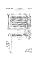
Figs. 1 and 2 are longitudinal sectional views of the mechanism showing the same in the positions, respectively, where the shed is closed and open; I
Fig. 3 is a section on line 3,3. Fig. 2; 1
Fig. 4 is a sectiononline 44, Fig. 1;
Fig.5 shows a fragment of whatappears in Fig. 1 on a larger scale;
Fig. 6 is a fragmentary front elevation of what appears in Fig. 5;
Figs? and 8 are sect-ions on linesq77 and 8 8, respectively, Fig. 5; and
Figs. 9 and 10 are a longitudinal section and a .plan'view of a modification of the mechanism.
Let ldes'ignate a pair of actuator members (here U-s'haped in plan and pivoted on a shaft 2). reciprocated togethertowardand together from an intermediate plane-,as by a suitably oscillated double crank 3 acting on the actuator members through Links lto reciprocate them." s I And let 5 designate'actu'ated members (here each a lever fu-lcrumed on shaft 2 and comprising two bars 5a with spaces 56- between themg a harness shaft 7, assumed to have heddles or equivalent (not hown) for the warp threads and guided at 8, and a link 9 pivotally connecting said actuated member with the shaft 7. I
Any one actuated member ,ande'ach actuatormember have coupling and keeper portions coactive to intercouple them and of which one such portion is movable, when said actuator members occupy given positions (as their proximating positions) in their reciprocating movement, substantially rectilineally and crosswise of the paths of movement of the actuatormembers intoand out of engagement with the other such position,thus (referringfiist to Figs. 1 to 8) I The coupling portion is here movable and applied to the actuated member, being a slide or bolt 10 movable in ways 11 extendingradh ally from its axis 2 and formed in its bars 5a, (see Figs. 5 to 8).
The keeper portion is here applied to each i. said actuator member has a fork 12 in which is a spring-pressed latch 13 whose projecting or catching portion 13 a.forms with an abutment 14- onsaid member the said recess 15, open radially. A single coupling portion is made to coact with the keeper portions of the two actuator members by constructingthe parts so that when the actuator members are in given positions in their reciprocating motion (here juxtaposedto each otherF igs. l and 5) the coupling portion may be moved into engagement with either keeper ortion and clear of the other. Of course t e two actuator members have as many pairs of the keeper portions as there are actuated members and hence coupling portions (Fig. 4). Vv'hen a coupling portion and keeper portion are engaged the coupling portion in the resent example contacts with the latch an the actuated member with the abutment 14; thus, or in any other way, once the coupling is established lost motion between the coupling and keeper portions may be avoided, to the end that, in the reciprocation of the actuated witheitherl actuator member the motion shall take place quietly and smoothly.
Itis not here materialby what medium the movement to couple or uncouple is effected,
but I have shown a pattern cylinder 16 having pegs 16afor displacing levers 17 which are normally urged toward the cylinder by springs 18 and are here connected with ex- 5 tensions a of the coupling portions (slotted as shown in Figs. 5 and 7 to receive the forks 12 of one actuator member) by links 19, the pattern cylinder being assumed to be rotated by any means step by step and adapted to effect changes in the positions of said coupling portions when the actuator members are juxtaposed to each other.
In Figs. 9 and 10 the portion of the actuated member which coacts with a portion of each of the actuator members is not movable in but is movable with the actuated member to effect the intercoupling and uncoupling. Said actuated member is here a lever having its said portion (here the coupling portion) 21 formed thereon, said lever having support on some part permitting it to partake of the reciprocation of either actuator member as well as to move to coact with either keeper portion, as such a pattern-controlled lever, 22, as that already described. The keeper portions are here essentially the same as before, their recesses being formed between the spring-pressed latches 23 (pivoted in blocks 24 on the actuator members) and the abutments 25, the coupling portion in this case contacting with both. the latch and abutment when engaged with a keeper portion. The links 9 may in this case be connected with the members 20 through pivoted shackles 9a (Fig. 9). The purpose in forming each keeper ortion with a latch yieldable: to the coup ing portion of the corresponding actuated member is to insure intended intercoupling of an actuated'member with an actuator member when transfer of any actuated member from one actuator member to the other is to occur, thus enabling such transfer to be effected even if the mechanism is operated at high speed. Having thus fully described my invention what I claim is: i 1. A shedding mechanism including a pair of actuator members reciprocating together toward and together from an intermediate plane, an actuated member to be reciprocated by either actuator member and forming part of a warp-shifting system, and means guided for movement substantially rectilineally and crosswise of the paths of the actuator members, when the latter occupy given positions in their reciprocating motion, and forming a coupling to intercouple said actuated member with either and uncouple it from the other actuator member. 7
2. A shedding mechanism including a pair of actuator members reciprocating together toward and together from an intermediate plane and an actuated member to be reciprocated by elther actuator member and form- W ng part of a Warp-shifting system, said actuated member and each actuator member having coupling and keeper portions coactive to intercouple them one of which portions is guided for movement and movable, when said actuator members occupy given positions in their reciprocating movement, substantially rectilineally and crosswise of the paths of the actuator members into and out of engagement with the other such portion.
3. A shedding mechanism including a pair of actuator members reciprocating together toward and together from an intermediate plane and an actuated member to be reciprocated by either actuator member and forming part of a warp-shifting system, said actuated member and each actuator member having coupling and recessed keeper portions coactive to intercouple them one of which portions is guided for movement and movable, when said actuator members occupy given positions in their reciprocating movement, substantially rectilineally and crosswise of the paths of the actuator members into and out of engagement with the other such portion, and one side of said keeper portion being a latch yieldable to the other portion when said actuator members approach said posi tions. I
4. A sheddingmechanism including a reciprocating actuator member and an actuated 9 member to be reciprocated by said actuator member and forming part of a warp-shifting system, said actuator and actuated members having coupling and recessed keeper portions coactive to intercouple them one of which portions is movable, when said actuator occupies a given position in its reciproeating movement, into and out of engagement with theother such portion, and one side of said keeper portion being latch yieldable to the'other portion when said actuator member approaches said position;
5. A shedding mechanism including a reciprocating actuator member, a warp-shifting system comprising an actuated member to be no reciprocated by said actuator member, said actuator and actuated miembers having coupling and keeper portions coactive to intercouple them together and said actuated member being movable back and forth to move its said portion into or out of coupling engagement with the other of said portions, and a support, independent of said system, on which said actuated member is pivotally movable with the actuator member and crosswise of 9 said back and forth movement when said portions are engaged with each other.
6. A shedding mechanism including. a re. ciprocating actuator member, a Warp-shifting system comprising an actuated member to be reciprocated by said actuator member, said actuator and actuated members having coupling and keeper portions coactive to intercouple them together and said actuated member being movable back and forth to 3 move its said portion into or out of coupling engagement with the other of said portions and a support, independent of said system on which said actuated member is pivotally movable with the actuator member and crosswise of said back and forth movement when said portions. are so engaged, said support affording means to shift said actuated member back and forth. a
7. A shedding mechanism including a set of side-by-side actuated members and an actuator member reciprocating toward and from the actuated members, there being as to each actuator member and each of the a actuated members a projection on one having a yielding latch and forming a coupling portion and said other member including a coupling portion movable into and out of latched engagement with the first coupling portion.
8. A shedding mechanism including aset of side-by-side actuated members and an actuator member reciprocating toward and from the actuated members, there being as to each actuator member and each of the actuated members a projection on one having a yielding latch and forming a coupling portion and in the other an opening to receive such coupling portion'and said other member including a coupling portion movable into and out of latched engagement with the I first coupling portion.
9. A shedding mechanism including a set of side-by-side actuated members and an actuator member reciprocating toward and from the actuated members, there being as to the actuator member and each of the actuated members a bearing on one such member for contact by the other and a yielding latch spaced from the bearing and forming therewith a coupling recess and the other member including a boltenterable and adapted to fit snugly between said bearing and the latch and withdrawable clear of the latch,
In testimony whereof I aflix my signature.
FRANK W. MERRICK.
Priority Applications (1)
| Application Number | Priority Date | Filing Date | Title |
|---|---|---|---|
| US430716A US1851719A (en) | 1930-02-24 | 1930-02-24 | Shedding mechanism for looms |
Applications Claiming Priority (1)
| Application Number | Priority Date | Filing Date | Title |
|---|---|---|---|
| US430716A US1851719A (en) | 1930-02-24 | 1930-02-24 | Shedding mechanism for looms |
Publications (1)
| Publication Number | Publication Date |
|---|---|
| US1851719A true US1851719A (en) | 1932-03-29 |
Family
ID=23708715
Family Applications (1)
| Application Number | Title | Priority Date | Filing Date |
|---|---|---|---|
| US430716A Expired - Lifetime US1851719A (en) | 1930-02-24 | 1930-02-24 | Shedding mechanism for looms |
Country Status (1)
| Country | Link |
|---|---|
| US (1) | US1851719A (en) |
-
1930
- 1930-02-24 US US430716A patent/US1851719A/en not_active Expired - Lifetime
Similar Documents
| Publication | Publication Date | Title |
|---|---|---|
| US1851719A (en) | Shedding mechanism for looms | |
| US4182380A (en) | Dobbies for weaving looms | |
| US1850328A (en) | Shedding mechanism for looms | |
| US1428572A (en) | Loom | |
| US4404993A (en) | Clutch arrangement for controlling a heddle of a weaving machine | |
| US1116814A (en) | Shedding mechanism for looms. | |
| US5074340A (en) | Yarn selector unit for a weft feeder | |
| US2160330A (en) | Door mounting and latching means | |
| US163064A (en) | Improvement in shedding fviechanisms for looivis | |
| US1511457A (en) | Drop-box-actuating mechanism for looms | |
| US2446688A (en) | Shuttle latching mechanism | |
| US434061A (en) | hattersley | |
| US232038A (en) | Shedding mechanism for looms | |
| US403565A (en) | Double-lift open-shed dobbies | |
| US3519027A (en) | Driving mechanism for the heald shafts of a weaving machine operating with a closed shed | |
| US6797A (en) | Island | |
| US1826654A (en) | Process for weaving | |
| US396522A (en) | Wire brothers | |
| US551191A (en) | Shuttle-box motion for looms | |
| US766975A (en) | Loom. | |
| US1954362A (en) | Method of and apparatus for positively transferring shuttles | |
| US844404A (en) | Selvage-motion for looms. | |
| US1554297A (en) | Jacquard indicator for drop-box looms | |
| US2357470A (en) | Pattern controlling mechanism for looms | |
| US466876A (en) | Island |